2019 MERCEDES-BENZ GLE COUPE radio
[x] Cancel search: radioPage 253 of 370
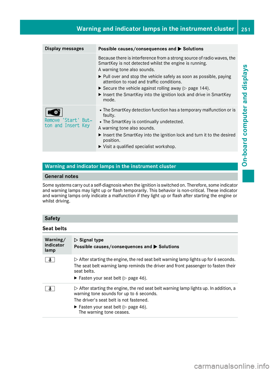
Display messages
Possible causes/consequences and
0050
0050Solutions Because there is interference from a strong source of radio waves, the
SmartKey is not detected whilst the engine is running.
A warning tone also sounds.
X Pull over and stop the vehicle safely as soon as possible, paying
attention to road and traffic conditions.
X Secure the vehicle against rolling away (Y page 144).
X Insert the SmartKey into the ignition lock and drive in SmartKey
mode. 00AF
Remove 'Start' But‐ Remove 'Start' But‐
ton and Insert Key ton and Insert Key R
The SmartKey detection function has a temporary malfunction or is
faulty.
R The SmartKey is continually undetected.
A warning tone also sounds.
X Insert the SmartKey into the ignition lock and turn it to the desired
position.
X Visit a qualified specialist workshop. Warning and indicator lamps in the instrument cluster
General notes
Some systems carry out a self-diagnosis when the ignition is switched on. Therefore, some indicator and warning lamps may light up or flash temporarily. This behavior is non-critical. These indicator
and warning lamps only indicate a malfunction if they light up or flash after starting the engine or
whilst driving. Safety
Seat belts Warning/
indicator
lamp
0051 0051
Signal type
Possible causes/consequences and 0050 0050Solutions 00E9
0051
After starting the engine, the red seat belt warning lamp lights up for 6 seconds.
The seat belt warning lamp reminds the driver and front passenger to fasten their
seat belts.
X Fasten your seat belt (Y page 46).00E9
0051
After starting the engine, the red seat belt warning lamp lights up. In addition, a
warning tone sounds for up to 6 seconds.
The driver's seat belt is not fastened.
X Fasten your seat belt (Y page 46).
The warning tone ceases. Wa
rning and indi cator lamps in the instrument cluster
251On-board computer and displays Z
Page 266 of 370
General notes
The multimedia system section in this Opera-
tor's Manual describes the basic principles for
operation. More information can be found in the Digital Operator's Manual. Important safety notes
G
WARNING
If you operate information systems and com-
munication equipment integrated in the vehi- cle when driving, you may be distracted from
the traffic situation. You could also lose con-
trol of the vehicle. There is a risk of an acci-
dent.
Only operate this equipment when the traffic
situation permits. If you are not sure that this
is possible, park the vehicle paying attention
to traffic conditions and operate the equip-
ment when the vehicle is stationary.
You must observe the legal requirements for the country in which you are currently driving whenoperating the multimedia system.
The multimedia system calculates the route to
the destination without taking the following into
account, for example:
R traffic lights
R stop and yield signs
R parking or stopping restrictions
R road narrowing
R other road and traffic rules and regulations
The multimedia system may give incorrect nav-
igation recommendations if the actual street/
traffic situation does not correspond with the
digital map's data.
For example:
R a diverted route
R the road layout or the direction of a one-way
street has been changed
For this reason, you must always observe road
and traffic rules and regulations during your
journey. Road and traffic rules and regulations
always have priority over multimedia system
driving recommendations. Navigation announcements are intended to
direct you while driving without diverting your
attention from the road and driving.
Please always use this feature instead of con-
sulting the map display for directions. Looking
at the icons or map display can distract you from
traffic conditions and driving, and increase the
risk of an accident.
This equipment complies with FCC radiation
exposure limits set forth for uncontrolled equip-
ment and meets the FCC radio frequency (RF)
Exposure Guidelines in Supplement C to OET65.
This equipment has very low levels of RF energy that is deemed to comply without maximum
permissive exposure evaluation (MPE). How-
ever, it is recommended to install it at a distance
of at least 8 inches (approx. 20 cm) between the
radiation source and a person's body (not
including limbs such as hands, wrists, feet and
legs). G
WARNING
Modifications to electronic components, their software as well as wiring can impair their
function and/or the function of other net-
worked components. In particular, systems
relevant to safety could also be affected. As a
result, these may no longer function as inten-
ded and/or jeopardize the operating safety of
the vehicle. There is an increased risk of an
accident and injury.
Never tamper with the wiring as well as elec-
tronic components or their software. You
should have all work to electrical and elec-
tronic equipment carried out at a qualified
specialist workshop. Function restrictions
For safety reasons, some functions are restric-
ted or unavailable while the vehicle is in motion. You will notice this, for example, because either
you will not be able to select certain menu items or a message will appear to this effect. 264
Function restrictionsMultimedia system
Page 267 of 370
Operating system
Overview
General notes !
Do not use the space in front of the display
for storage. Objects placed here could dam-
age the display or impair its function. Avoid
any direct contact with the display surface.
Pressure on the display surface may result in
impairments to the display, which could be
irreversible.
Wearing polarized sunglasses may impair your
ability to read the display.
The display has an automatic temperature-con- trolled switch-off feature. The brightness is
automatically reduced if the temperature is too
high. The display may temporarily switch off
completely.
Cleaning instructions !
Do not touch the display. The display has a
very sensitive high-gloss surface; there is a
risk of scratching. If you have to clean the
screen, however, use a mild cleaning agent
and a soft, lint-free cloth.
The display must be switched off and have
cooled down before you start cleaning. Do not
apply pressure to the display surface when
cleaning it, as this could cause irreversible dam-
age to the display.
Switching the multimedia system
on/off X
Press the 0043control knob.
Adjusting the volume X
Turn the 0043control knob.
The volume is adjusted:
R for the currently selected media source
R during traffic or navigation announcements
R in hands-free mode during an active call
Switching the sound on or off X
Press the 0063button on the control panel.
If the audio output is switched off, the status
line will show the 0063symbol. If you switch the media source or set the volume, the sound
is automatically switched on.
i Navigation announcements will be heard
even if the sound is muted.
Functions The multimedia system has the following func-
tions:
R Radio mode
R Media mode with media search
R Sound systems
R Navigation system
COMAND: navigation via the hard drive
Audio 20: navigation via SD card
R Communication functions
R SIRIUS Weather (COMAND)
R Vehicle functions with system settings
R Favorites functions
Controller The controller in the center console lets you:
R select menu items on the display
R enter characters
R select a destination on the map
R save entries
The controller can be:
R turned 3
R slid left or right 1
R slid forwards or back 4
R slid diagonally 2
R pressed briefly or pressed and held 7
Back button You can use the
0038button to exit a menu or to
call up the main menu of the current operating
mode.
X To exit the menu: briefly press the0038
button.
The multimedia system changes to the next
higher menu level in the current operating
mode.
X To call up the main menu: press the0038
button for longer than two seconds.
The multimedia system changes to the main
menu of the current operating mode. Operating system
265Multimedia system Z
Page 295 of 370
Programming
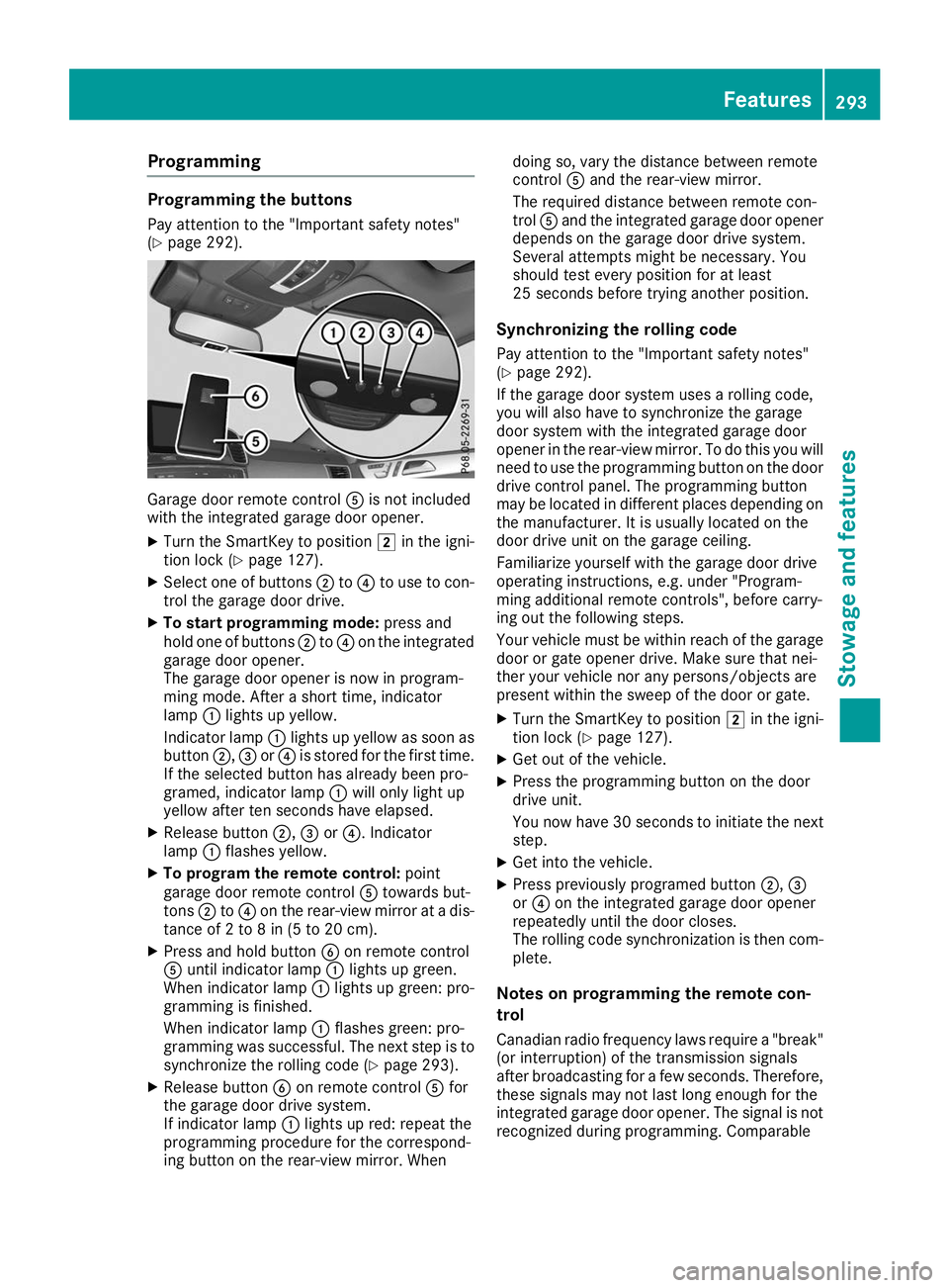
Programming the buttons
Pay attention to the "Important safety notes"
(Y page 292). Garage door remote control
0083is not included
with the integrated garage door opener.
X Turn the SmartKey to position 0048in the igni-
tion lock (Y page 127).
X Select one of buttons 0044to0085 to use to con-
trol the garage door drive.
X To start programming mode: press and
hold one of buttons 0044to0085 on the integrated
garage door opener.
The garage door opener is now in program-
ming mode. After a short time, indicator
lamp 0043lights up yellow.
Indicator lamp 0043lights up yellow as soon as
button 0044,0087or0085 is stored for the first time.
If the selected button has already been pro-
gramed, indicator lamp 0043will only light up
yellow after ten seconds have elapsed.
X Release button 0044,0087or0085. Indicator
lamp 0043flashes yellow.
X To program the remote control: point
garage door remote control 0083towards but-
tons 0044to0085 on the rear-view mirror at a dis-
tance of 2 to 8 in (5 to 20 cm).
X Press and hold button 0084on remote control
0083 until indicator lamp 0043lights up green.
When indicator lamp 0043lights up green: pro-
gramming is finished.
When indicator lamp 0043flashes green: pro-
gramming was successful. The next step is to synchronize the rolling code (Y page 293).
X Release button 0084on remote control 0083for
the garage door drive system.
If indicator lamp 0043lights up red: repeat the
programming procedure for the correspond-
ing button on the rear-view mirror. When doing so, vary the distance between remote
control
0083and the rear-view mirror.
The required distance between remote con-
trol 0083and the integrated garage door opener
depends on the garage door drive system.
Several attempts might be necessary. You
should test every position for at least
25 seconds before trying another position.
Synchronizing the rolling code
Pay attention to the "Important safety notes"
(Y page 292).
If the garage door system uses a rolling code,
you will also have to synchronize the garage
door system with the integrated garage door
opener in the rear-view mirror. To do this you will
need to use the programming button on the door
drive control panel. The programming button
may be located in different places depending on the manufacturer. It is usually located on the
door drive unit on the garage ceiling.
Familiarize yourself with the garage door drive
operating instructions, e.g. under "Program-
ming additional remote controls", before carry-
ing out the following steps.
Your vehicle must be within reach of the garage
door or gate opener drive. Make sure that nei-
ther your vehicle nor any persons/objects are
present within the sweep of the door or gate.
X Turn the SmartKey to position 0048in the igni-
tion lock (Y page 127).
X Get out of the vehicle.
X Press the programming button on the door
drive unit.
You now have 30 seconds to initiate the next
step.
X Get into the vehicle.
X Press previously programed button 0044,0087
or 0085 on the integrated garage door opener
repeatedly until the door closes.
The rolling code synchronization is then com- plete.
Notes on programming the remote con-
trol
Canadian radio frequency laws require a "break" (or interruption) of the transmission signals
after broadcasting for a few seconds. Therefore,
these signals may not last long enough for the
integrated garage door opener. The signal is not recognized during programming. Comparable Features
293Stowage and features Z
Page 338 of 370
sudden loss of pressure, bring the vehicle to a
halt by braking carefully. Avoid abrupt steering
movements.
The tire pressure monitor has a yellow warning
lamp in the instrument cluster for indicating
pressure loss or a malfunction. Whether the
warning lamp flashes or lights up indicates
whether a tire pressure is too low or the tire
pressure monitor is malfunctioning:
R if the warning lamp is lit continuously, the tire
pressure on one or more tires is significantly
too low. The tire pressure monitor is not mal- functioning.
R if the warning lamp flashes for approximately
a minute and then remains lit constantly, the
tire pressure monitor is malfunctioning.
In addition to the warning lamp, a message
appears in the multifunction display. Observe
the information on display messages
(Y page 245).
It may take up to ten minutes for a malfunction
of the tire pressure monitor to be indicated. A
malfunction will be indicated by the tire pres-
sure warning lamp flashing for approximately
one minute and then remaining lit. When the
malfunction has been rectified, the tire pressure warning lamp goes out after a few minutes of
driving.
The tire pressure values indicated by the on-
board computer may differ from those meas-
ured at a gas station with a pressure gauge. The
tire pressures shown by the on-board computer
refer to those measured at sea level. At high
altitudes, the tire pressure values indicated by a pressure gauge are higher than those shown by
the on-board computer. In this case, do not
reduce the tire pressures.
The operation of the tire pressure monitor can
be affected by interference from radio transmit- ting equipment (e.g. radio headphones, two-wayradios) that may be being operated in or near the
vehicle.
Checking the tire pressure electroni-
cally X
Make sure that the SmartKey is in position 0048
(Y page 127) in the ignition lock.
X Press the 0059or0065 button on the steering
wheel to select the Serv.
Serv. menu. X
Press the 0063or0064 button to select
Tire Pressure Tire Pressure.
X Press 0076.
The current tire pressure of each tire is shown in the multifunction display.
If the vehicle has been parked for longer than
20 minutes, the Tire pressure will be Tire pressure will be
displayed after driving a few minutes
displayed after driving a few minutes
message appears.
After a teach-in process, the tire pressure mon-
itor automatically detects new wheels or new
sensors. As long as a clear allocation of the tire
pressure value to the individual wheels is not
possible, the Tire
Tire Pressure
Pressure Monitor MonitorActive
Active
display message is shown instead of the tire
pressure display. The tire pressures are already being monitored.
If an emergency spare wheel is mounted, the
system may continue to show the tire pressure
of the wheel that has been removed for a few
minutes. Therefore, remember that the dis-
played tire pressure may not be the same as the
emergency spare wheel's current tire pressure.
Tire pressure monitor warning mes-
sages If the tire pressure monitor detects a pressure
loss in one or more tires, a warning message is
shown in the multifunction display. The yellow
tire pressure warning lamp then lights up.
R If the Please Correct Tire Pressure
Please Correct Tire Pressure
message appears in the multifunction display, the tire pressure in at least one tire is too low.
The tire pressure must be corrected when the
opportunity arises.
R If the Check Tires Check Tires message appears in the
multifunction display, the tire pressure in at
least one tire has dropped significantly. The
tires must be checked.
R If the Warning Warning Tire
TireMalfunction
Malfunction message
appears in the multifunction display, the tire
pressure in at least one tire has dropped sud-
denly. The tires must be checked.
Be sure to observe the instructions and safety
notes in the display messages in the "Tires" sec-
tion (Y page 245).
If the positions of the wheels on the vehicle are changed, the tire pressures may be displayed in
the wrong positions for a short time. This is rec-
tified after a few minutes of driving, and the tire pressures are displayed for the correct posi-
tions. 336
Tire pressureWheels and tires
Page 339 of 370
Restarting the tire pressure monitor
When you restart the tire pressure monitor, all
existing warning messages are deleted and the
warning lamps go out. The monitor uses the cur-
rently set tire pressures as the reference values
for monitoring. In most cases, the tire pressure
monitor will automatically detect the new refer- ence values after you have changed the tire
pressure. However, you can also set reference
values manually as described here. The tire
pressure monitor then monitors the new tire
pressure values.
X Set the tire pressure to the value recommen-
ded for the corresponding driving situation on the Tire and Loading Information placard on
the driver's side B-pillar (Y page 330).
You can find more tire pressure values for
various operating conditions in the tire pres-
sure table inside the fuel filler flap
(Y page 331).
X Make sure that the tire pressure is correct on
all four wheels.
X Make sure that the SmartKey is in position 0048
in the ignition lock.
X Press the 0059or0065 button on the steering
wheel to select the Serv. Serv.menu.
X Press the 0063or0064 button to select
Tire Pressure
Tire Pressure .
X Press 0076.
The multifunction display shows the current
tire pressure for the individual tires or the
Tire pressure will be displayed Tire pressure will be displayed
after driving a few minutes after driving a few minutes message.
X Press the 0064button.
The Use
Use Current
Current Pressures
Pressures as
asNew
New Ref‐
Ref‐
erence
erence Values
Valuesmessage appears in the mul-
tifunction display.
If you wish to confirm the restart:
X Press the 0076button.
The Tire
Tire Press.
Press. Monitor
Monitor Restarted
Restarted mes-
sage appears in the multifunction display.
After driving for a few minutes, the system
checks whether the current tire pressures are
within the specified range. The new tire pres- sures are then accepted as reference values
and monitored.
If you wish to cancel the restart: X Press the 0038button.
The tire pressure values stored at the last
restart will continue to be monitored. Radio type approval for the tire pres-
sure monitor Country Radio type approval number
USA FCC ID: MRXGG4
FCC ID: MRXMC34MA4
This device complies with Part 15
of the FCC Rules. Operation is
subject to the following two con- ditions: (1) This device may not
cause harmful interference, and
(2) This device must accept any
interference received, including
interference that may cause
undesired operation. Canada IC: 2546A-GG4;
IC: 2546A- MC34MA4;
Le présent appareil est conforme
aux CNR d'Industrie Canada
applicables aux appareils radio
exempts de license. L'exploita-
tion est autorisée aux deux con-
ditions suivantes: (1) l'appareil
ne doit pas produire de brouil-
lage, et (2) l'utilisateur de l'ap-
pareil doit accepter tout brouil-
lage radioélectrique subi, même
si le brouillage est susceptible
d'en compromettre le fonc-
tionnement. Loading the vehicle
Instruction labels for tires and loads
G
WARNING
Overloaded tires can overheat, causing a
blowout. Overloaded tires can also impair the steering and driving characteristics and lead
to brake failure. There is a risk of accident.
Observe the load rating of the tires. The load
rating must be at least half of the GAWR of
your vehicle. Never overload the tires by
exceeding the maximum load.
Two instruction labels on your vehicle show the maximum possible load.
(1) The Tire and Loading Information placard is on the B-pillar on the driver's side. The Tire Loading the vehicle
337Wheels and tires Z
Page 359 of 370
Information regarding technical data
i The data stated here specifically refers to a
vehicle with standard equipment. Consult an
authorized Mercedes-Benz Center for the
data for all vehicle variants and trim levels. Vehicle electronics
Installing wireless devices and mobile
phones G
WARNING
The electromagnetic radiation from two-way
radios can interfere with the vehicle electron-
ics if two-way radios are manipulated or ret-
rofitted incorrectly. This could jeopardize the
operating safety of the vehicle. There is a risk of an accident.
You should have all work on electrical and
electronic components carried out at a quali-
fied specialist workshop. G
WARNING
If you incorrectly operate two-way radios in
the vehicle, the electromagnetic radiation
may interfere with the vehicle electronics, for example if:
R the two-way radio is not connected to an
exterior antenna
R the exterior antenna is not correctly moun-
ted or is not low-reflection
This could jeopardize the operating safety of
the vehicle. There is a risk of an accident.
Have the low-reflection exterior antenna
installed at a qualified specialist workshop.
Always connect two-way radios to the low-
reflection exterior antenna when operating in the vehicle.
! The operating permit may be invalidated if
the instructions for installation and use of
two-way radios are not observed. In particular, the following requirements must
be complied with:
R only approved wavebands may be used
R observe the maximum permissible output
in these wavebands
R only approved antenna positions may be
used
Excessive levels of electromagnetic radiation
may cause damage to your health and the health of others. Using an exterior antenna takes into
account current scientific discussions relating
to the possible health hazards that may result
from electromagnetic fields.
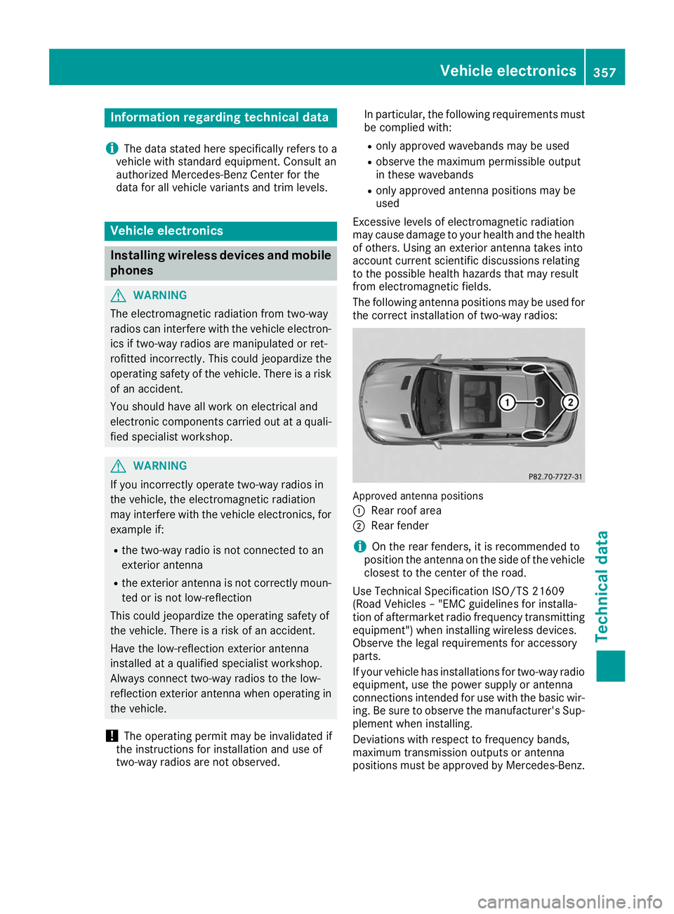
The following antenna positions may be used for
the correct installation of two-way radios: Approved antenna positions
0043
Rear roof area
0044 Rear fender
i On the rear fenders, it is recommended to
position the antenna on the side of the vehicle
closest to the center of the road.
Use Technical Specification ISO/TS 21609
(Road Vehicles – "EMC guidelines for installa-
tion of aftermarket radio frequency transmitting
equipment") when installing wireless devices.
Observe the legal requirements for accessory
parts.
If your vehicle has installations for two-way radio
equipment, use the power supply or antenna
connections intended for use with the basic wir-
ing. Be sure to observe the manufacturer's Sup- plement when installing.
Deviations with respect to frequency bands,
maximum transmission outputs or antenna
positions must be approved by Mercedes-Benz. Vehicle electronics
357Technical data Z
Page 360 of 370
The maximum transmission output (PEAK) at the
base of the antenna must not exceed the fol-
lowing values: Frequency band Maximum
transmission output Short wave
3 - 54 MHz 100 W
4 m waveband
74 - 88 MHz 30 W
2 m waveband
144 - 174 MHz 50 W
Trunked radio system/
Tetra
380 - 460 MHz 10 W
70 cm waveband
400 - 460 MHz 35 W
Mobile communications
(2G/3G/4G) 10 W
The following can be used in the vehicle without
restrictions:
R Two-way radios with a maximum transmission
output of up to 100 mW
R Two-way radios with transmitter frequencies
in the 380 - 410 MHz waveband and a maxi-
mum transmission output of up to 2 W
(trunked radio/Tetra)
R Mobile phones (2G/3G/4G)
There are no restrictions when positioning the
antenna on the outside of the vehicle for the
following wavebands:
R Trunked radio system/Tetra
R 70 cm waveband
R 2G/3G/4G Identification plates
Vehicle identification plate with vehi-
cle identification number (VIN)
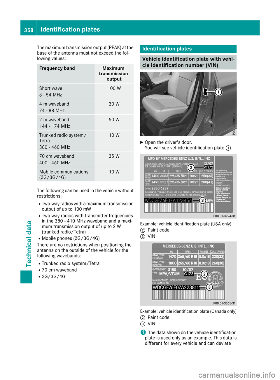
X
Open the driver's door.
You will see vehicle identification plate 0043. Example: vehicle identification plate (USA only)
0044 Paint code
0087 VIN Example: vehicle identification plate (Canada only)
0044 Paint code
0087 VIN
i The data shown on the vehicle identification
plate is used only as an example. This data is
different for every vehicle and can deviate 358
Identification platesTechnical data