2019 MERCEDES-BENZ EQC SUV load capacity
[x] Cancel search: load capacityPage 263 of 629
Bic
ycle rack function &
WARNING Risk of an accident when
using the bicycle rack incor rectly
The bicycle rack may become de tach ed from
th eve hicle in thefo llowing cases:
R the permissible load capacity of the
trailer hitch is exceeded.
R the bicycle rack is used incor rectl y.
R the bicycle rack is secured tothe ball
neck beneath the ball head.
Obser vethefo llowing foryo ur ow n sa fety
and that of other road users:
R always adhere tothe permissible load
capacity of the trailer hitch.
R only use the bicycle rack totranspo rt
bicycles.
R always mount the bicycle rack properly by
attaching tothe ball head and the ball
neck guide pin, if possible. R
when transporting four bic ycles, alw ays
use bic ycle rack s which ha veadditional
suppo rton the ball neck guide pin.
R only use bicycle rack s appr ovedby
Mercedes-Benz.
R always obser vethe bicycle rack operating
instructions. *
NO
TEDama geto, or cra cks on, the
trailer hitch due tounsuitable bic ycle
ra ck s or bicycle rack s being used incor‐
re ctly #
use only bicycle rack s appr ovedby
Mercedes-Benz. Tr
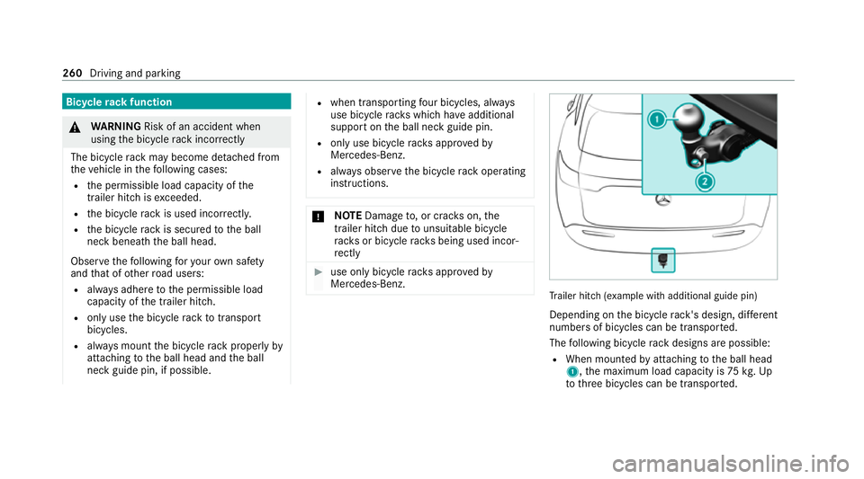
ailer hit ch(examp le with additional guide pin)
Depending on the bicycle rack 's design, dif fere nt
numbe rsof bicycles can be transpor ted.
The following bicycle rack designs are possible:
R When mounted byattaching tothe ball head
1, the maximum load capacity is 75kg.Up
to thre e bicycles can be transpor ted. 260
Driving and parking
Page 264 of 629
R
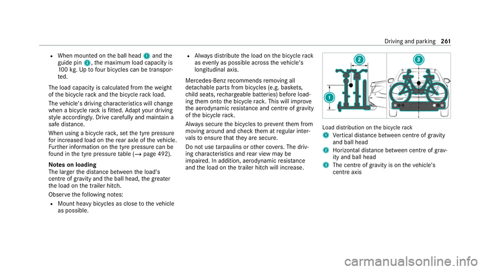
When mounted on the ball head 1and the
guide pin 2,the maximum load capacity is
10 0kg .Up tofour bic ycles can be transpor‐
te d.
The load capacity is calculated from thewe ight
of the bicycle rack and the bicycle rack load.
The vehicle's driving characteristics will change
when a bicycle rack isfitted. Adapt your driving
st yle accordingly. Drive carefully and maintain a
safe dis tance.
When using a bicycle rack , set the tyre pressure
fo r increased load on there ar axle of theve hicle.
Fu rther information on the tyre pressure can be
fo und in the tyre pressure table (/ page 492).
Note s on loading
The larger the dis tance between the load's
cent reof gr avity and the ball head, the greater
th e load on the trailer hitch.
Obser vethefo llowing no tes:
R Mount heavy bicycles as close totheve hicle
as possible. R
Alw ays distribute the load on the bicycle rack
as eve nly as possible across theve hicle's
longitudinal axis.
Mercedes-Benz recommends removing all
de tach able parts from bicycles (e.g. bask ets,
ch ild seats, rech arge able bat teries) before load‐
ing them onto the bicycle rack . This will impr ove
th e aerodynamic resis tance and centre of gr avity
of the bicycle rack.
Alw ays secure the bicycles toprev ent them from
moving around and check them at regular inter‐
va ls to ensure that they are secure.
Do not use tarp aulins or other co vers. The driv‐
ing characteristics and rear view may be
impaired. In addition, aerodynamic resis tance
and the load on the trailer hitch will increase. Load distribution on
the bicycle rack
1 Vertical dis tance between centre of gr avity
and ball head
2 Horizon tal dis tance between centre of gr av‐
ity and ball head
3 The centre of gr avity is on theve hicle's
centre axis Driving and parking
261
Page 502 of 629

When
replacing tyres, make sure tofit the
cor rect:
R Designation
R Manufactu rer
R Type &
WARNING Risk of inju rythro ugh exceed‐
ing the specified tyre load-bearing capa‐
city or the permissible speed rating
Exceeding the specified tyre load-bearing
capacity or the permissible speed rating may
lead totyre dama geand tothe tyres bur st‐
ing. #
Therefore, only use tyre types and sizes
appr ovedfo ryo ur vehicle model. #
Obser vethe tyre load-bearing capacity
ra ting and speed rating requ iredfor
yo ur vehicle. *
NO
TEVehicle and tyre damage thro ugh
tyre types and sizes that ha venot been
appr oved Fo
r saf etyre asons, on lyuse tyres, wheels
and accessories which ha vebeen specially
appr ovedby Mercedes-Benz foryo ur vehicle.
These tyres are specially adap tedto the con‐
trol sy stems, such as ABS, ESP ®
and
4MATIC, and mar ked as follo ws:
R MO = Mercedes-Benz Original
R MOE = Mercedes-Benz Original Extended
(run-flat tyres only for cer tain wheels)
R MO1 = Mercedes-Benz Original (only cer‐
tain AMG tyres)
Cer tain characteristics, such as handling,
ve hicle noise emissions, fuel consum ption,
et c. may otherwise be adversely af fected.
Fu rthermore, other tyre sizes could result in
th e tyres rubbing against the body and axle
components when loaded. This could result
in damage tothe tyre or theve hicle. Only use tyres, wheels and accessories
that
ha ve been checked and recommended by
Mercedes-Benz. *
NO
TERisk todriving saf ety from retrea‐
ded tyres Re
treaded tyres are nei ther tested nor rec‐
ommended byMercedes-Benz, since pr evi‐
ous damage cannot alw ays be de tected on
re treaded tyres.
Fo rth is reason driving saf ety cannot be guar‐
anteed. #
Do not use used tyres if you ha veno
information about their pr evious usage. *
NO
TEPossible damage towheels or
tyres when driving over obs tacles Lar
gewheels ha vea lo wer tyre section width.
The lo werth e tyre section width, the greater
is therisk of damage towheels or tyres when
driving over obs tacles. Wheels and tyres
499
Page 505 of 629
R
Protect the tyres from conta ct withoil,
grease or fuel. Overview of
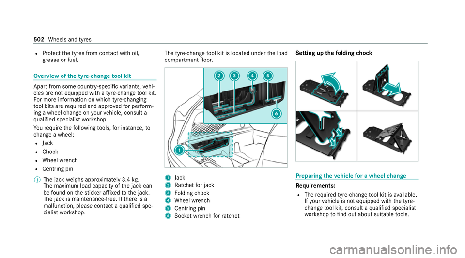
the ty re-change tool kit Apart from some countr
y-specific variants, vehi‐
cles are not equipped with a tyre-change tool kit.
Fo r more information on which tyre-changing
to ol kits are requ ired and appr ovedfo r per form‐
ing a wheel change on your vehicle, consult a
qu alified specialist workshop.
Yo ure qu ire thefo llowing tools, for ins tance, to
ch ange a wheel:
R Jack
R Chock
R Wheel wrench
R Cent ring pin
% The jack weighs appr oximately 3.4 kg.
The maximum load capacity of the jack can
be found on thest icke r af fixe dto the jac k.
The jack is maintenance-free. If there is a
malfunction, please conta ct aqualified spe‐
cialist workshop. The tyre-change
tool kit is located under the load
compartment floor. 1
Jack
2 Ratchet for jack
3 Folding chock
4 Wheel wrench
5 Centring pin
6 Socket wrench forra tchet Setting up the
folding chock Prepa
ring theve hicle for a wheel change Re
quirements:
R The requ ired tyre-change tool kit is available.
If yo ur vehicle is not equipped with the tyre-
ch ange tool kit, consult a qualified specialist
wo rkshop tofind out about suitable tools. 502
Wheels and tyres
Page 520 of 629
Ro
of load EQC 400 4MATIC
Maximum
roof load 75kg Te
ch nical data of the high-voltage bat tery Missing
values werenot available at the time of
going topress.
High-voltage battery EQC 400 4MATIC
Ty
pe Lithium-ion
Battery energy con tent
(NEDC) 80 kWh
Ra nge
Charge time – mode 4
wi th appr ox.11 0 kW peak
ch arging capacity App
rox.
40 min
Charge time – mode 3
wi th 7.4 kW charging capacity App
rox. 11 h EQC 400 4MATIC
Char
getime – mode 2
wi th 3.7 kW charging capacity App
rox. 21 h
30 min
Charge time – mode 2
with 2.3 kW charging capacity App
rox. 40 h
45 min
Charge time – mode 2
wi th 1.8 kW charging capacity App
rox. 53 h
15 min The
charge times – modes 2 and 3 are forch arg‐
ing from 10%to 100% of the usable battery capa‐
city with alternating cur rent.
The charge time – mode 4 is forch arging from
10 %to 80% of the usable battery capacity with
direct cur rent.
The charging capacity de term ines thech arge
time, in addition tothe battery charge status and
th e ambient temp erature. The charging capacity
depends on the supply voltage, the cur rent
intensity and the type of po wer supp ly. Tr
ailer hitch Gene
ral no tes on the trailer hit ch Modifications
tothe engine cooling sy stem may
be necessar y,depending on theve hicle model.
The retrofitting of a trailer hitch is only pe rmissi‐
ble if a towing capacity is specified in your vehi‐
cle documents.
Fu rther information can be obtained at a quali‐
fi ed specialist workshop. Te
ch nical da ta517
Page 521 of 629
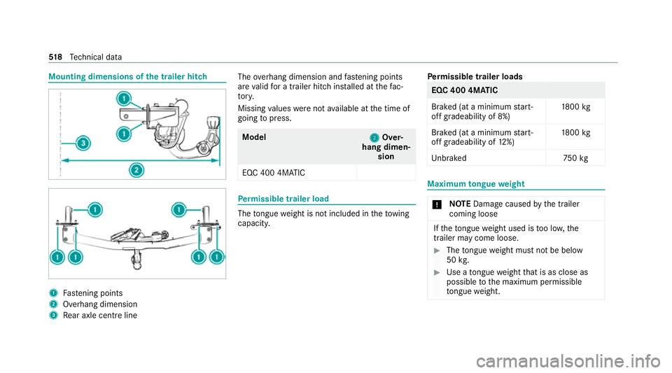
Mounting dimensions of
the trailer hit ch 1
Fastening points
2 Overhang dimension
3 Rear axle centre line The
overhang dimension and fastening points
are valid for a trailer hitch ins talled at thefa c‐
to ry.
Missing values werenot available at the time of
going topress. Model
2
2Over‐
hang dimen‐ sion
EQC 400 4MATIC Pe
rm issible trailer load The
tongue weight is not included in theto wing
capacity. Pe
rm issible trailer loads EQC 400 4MATIC
Bra
ked (at a minimum start-
off gradeability of 8%) 18
00 kg
Braked (at a minimum start-
off gradeability of 12%) 18
00 kg
Unb rake d7 50kg Maximum
tongue weight *
NO
TEDama gecaused bythe trailer
coming loose If
th eto ngue weight used is too lo w,the
trailer may come loose. #
The tongue weight must not be below
50 kg. #
Use a tongue weight that is as close as
possible tothe maximum permissible
to ngue weight. 518
Tech nical da ta
Page 617 of 629
SV
HC (substances of very high con‐
cern ).......................................................... .26
Switch-off delay time Exterior ................................................ 14 0
Interior ................................................. 14 2
Synchronisation function Activating/deactivating (multimedia
sy stem) ................................................ 15 2
Sy stem settings
Ac tivating/deactivating PIN pr otec‐
tion ...................................................... 335
Re set function (multimedia sy stem) ....3 38
Setting the dis tance unit ..................... 334
Setting the time and date automati‐
cally ..................................................... 330
Setting the time zone .......................... 330
Setting the time/date form at .............. 330
Swit ching transmission of theve hicle
position on/off .................................... 331
Sy stem settings
see Blue tooth®
see Data import/export
see Language
see Software update see
Wi-Fi T
Ta ilgate ...................................................... .82
Closing .................................................. 83
HANDS-FREE ACCESS .......................... .85
Limiting the opening angle .................... 86
Opening .................................................82
Opening dimensions ............................5 16
Un locking (emer gency key) .................. .86
Ta ke -back of end-of-life vehicles .............. 17
Pr otection of the environment ............... 17
Te ch nical data
Axle load (trailer operation) ................. 519
Fa stening points (trailer hitch) .............5 18
Information ..........................................5 09
Mounting dimensions (trailer hitch) ..... 51 8
No tes (trailer hitch) .............................. 517
Overhang dimension (trailer hitch) .......5 18
To ngue weight ...................................... 51 8
To wing capacity (trailer operation) ...... .518
Ve hicle identification plate ...................5 11
Te lephone ........................................ .272, 393
Ac tivating functions du ring a call ........ 398 Calls wi
thseveral participants ............ .398
Changing a function ............................ 395
Connecting a mobile phone (Near
Field Communication (NFC)) .............. .397
Connecting a mobile phone (Pass‐
ke y) .................................................... .394
Connecting a mobile phone (Secure
Simple Pairing) .................................... 394
Disconnecting a mobile phone ............ 396
Importing con tacts .............................. 401
Importing contacts (o verview) ............ .401
Incoming call during an existing call .... 399
Information .......................................... 394
Inter changing mobile phones .............. 395
Locking theve hicle (mobile phone) .......78
Menu (on-board computer) .................. 272
Mobile phone voice recognition .......... 398
No tes ................................................... 391
Operating modes ................................. 394
Re ception and transmission volume .... 397
Re placing mobile phones .................... 396
Setting theringtone ............................ 398
St arting theve hicle (mobile phone) ..... 16 4
Switching mobile phones (Near Field
Communication (NFC)) ........................ 397
Te lephone menu overview ...................3 9361 4
Index
Page 619 of 629
To
uchscreen (media display)
Entering characters ............................ .326
Operating ............................................ 299
Setting acou stic operating feedback ... 300
To w- aw ay protection
Fu nction ................................................ 97
Priming/deactivating ............................. 97
To w- bar sy stem ...................................... .262
To w- starting ............................................. 486
To wing away ............................................ 483
To wing eye
Ins talling .............................................. 486
St orage location ..................................4 85
To wing me thods ...................................... 482
Tr af fic announcements
Ac tivating/deactivating ...................... .447
Tr af fic information .................................. 372
Car-to-X-Communication .................... .376
Displ aying the tra ffic map .................... 374
Displ aying traf fic incidents .................. 375
Extending a Li veTraf fic Information
subscription ......................................... 374
Live Traf fic Information ........................ 373Overview .............................................
372
Re gis tering Live Traf fic Information ..... 373
Switching on the display ......................3 75
Tr af fic map
see Map
Tr af fic Sign Assist .................................. .248
Fu nction/no tes ................................... 24 8
Setting ................................................. 250
Sy stem limitations ...............................2 48
Tr ailer hitch
Axle load .............................................. 519
Bicycle rack ......................................... 260
Ca re .................................................... 469
Coupling up/uncoupling a trailer ........ 258
Extending/r etra cting the ball neck ...... 256
Fa stening points ..................................5 18
Gene ral no tes ...................................... 517
Mounting dimensions ........................... 51 8
No tes .................................................. 256
Overhang dimension ............................5 18
Soc ket ................................................. 258
To ngue weight ...................................... 51 8
To wing capacity .................................. .518 Tr
ailer operation
Ac tive Blind Spot Assi st....................... 252
Ac tive Lane Keeping Assist ................. 253
Bicycle rack ......................................... 260
Coupling up/uncoupling a trailer ........ 258
Extending/r etra cting the ball neck ...... 256
No tes .................................................. 256
Soc ket ................................................. 258
Tr ailer stabilisation
Fu nction/no tes ................................... 201
Tr ansfer redve hicle data
Android Auto ........................................ 41 5
Apple CarPl ay®
.................................... 41 5
Tr ansmission
Cr aw ler mode ...................................... 226
DIRECT SELECT le ver ........................... 173
Drive prog ram display ......................... .172
Drive prog rams ................................... .169
DY NA MIC SELECT switch .................... 16 9
Engaging drive position ........................ 175
Engaging pa rkposition .........................1 74
Engaging reve rsege ar .......................... 174
Tr ansmission position display .............. 173
Tr ansmission positions ........................ 17361 6
Index