2019 MERCEDES-BENZ CLA COUPE tyre pressure
[x] Cancel search: tyre pressurePage 6 of 645
Climate control
........................................ 14 6
Overview of climate contro l systems ..........1 46
Operating the climate control sy stem ......... 147 Driving and pa
rking ................................. 15 6
Driving ........................................................ 15 6
DY NA MIC SELECT switch ............................1 66
Manual transmission .................................. 16 8
Au tomatic transmission .............................. 17 0
Fu nction of the 4MATIC .............................. 175
Re fuelling .................................................... 175
Pa rking ........................................................ 181
Driving and driving sa fety sy stems .............. 191
Tr ailer hit ch................................................ 252
Bicycle rack function .................................. 255
Ve hicle towing instructions ........................ .257 Instrument Display and on-board
compu ter.................................................. 258
Instrument display overview ...................... .258
Overview of the buttons on thesteering
wheel ..........................................................2 59
Operates the on-board computer ............... 260 Ad
justing the design of the instrument
display ........................................................ 261
Showing display conte nt onthe instru‐
ment clus ter ............................................... 262
Overview of displa yson the multifunc‐
tion display .................................................2 63
Ad justing the instrument lighting ............... 264
Menus and submenus ................................ 264
Head-up Display .......................................... 271 LINGU
ATRO NIC ......................................... 272
No tes on operating saf ety .......................... .272
Operation ................................................... 272
Using LINGU ATRO NIC ef fectively ................ 275
Essential voice commands .......................... 276 MBUX multimedia sy
stem ...................... 290
Overview and operation .............................. 290
Sy stem settings .......................................... 326
Fit & Healt hy............................................... 336
Na vigation ................................................... 341
Te lephone .................................................. .386
Online and Internet functions ..................... 421
Media ........................................................ .430 Ra
dio .......................................................... 438
Sound .........................................................4 41 Maintenance and care
.............................445
ASS YST PLUS service inter val display ........ 445
Engine compartment .................................. 446
Cleaning and care ...................................... .452 Breakdown assi
stance ............................ 462
Emergency ................................................. .462
Flat tyre ...................................................... 464
Battery (vehicle) ......................................... 470
To w- starting or towing away ....................... 476
Electrical fuses ........................................... 482 Wheels and tyres
..................................... 485
No tes on noise or unusual handling char‐
acteristics .................................................. .485
No tes on regular lyinspecting wheels and
tyres .......................................................... .485
No tes on snow chains ................................ 485
Ty re pressure .............................................. 486
Wheel change ............................................ .495 Contents
3
Page 14 of 645
1
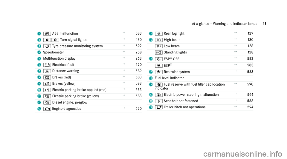
! ABS malfunction →
583
2 #! Turn signal lights →
13 0
3 h Tyre pressure monitoring sy stem →
592
4 Speedome ter →
258
5 Multifunction display →
263
6 # Electrical fault →
590
7 L Distance warning →
589
8 J Brakes (red) →
583
9 J Brakes (yellow) →
583
A ! Electric parking brake applied (red) →
583
B ! Electric parking brake (yellow) →
583
C % Diesel engine: preglow
D ; Engine diagno stics →
590 E
R Rear fog light →
12 9
F K High beam →
13 0
L Low beam →
12 8
T Standing lights →
12 8
G å ESP®
OFF →
583
÷ ESP®
→
583
H 6 Restra int sy stem →
583
I Fuel le vel indicator
J æ Fuelreser vewith fuel filler cap location
indicator →
590
K Ù Electric po werst eering malfunction →
594
L ü Seat belt not fastened →
588
M ï Trailer hit chnot operational →
594 At
aglance – Warning and indicator lamps 11
Page 16 of 645
1
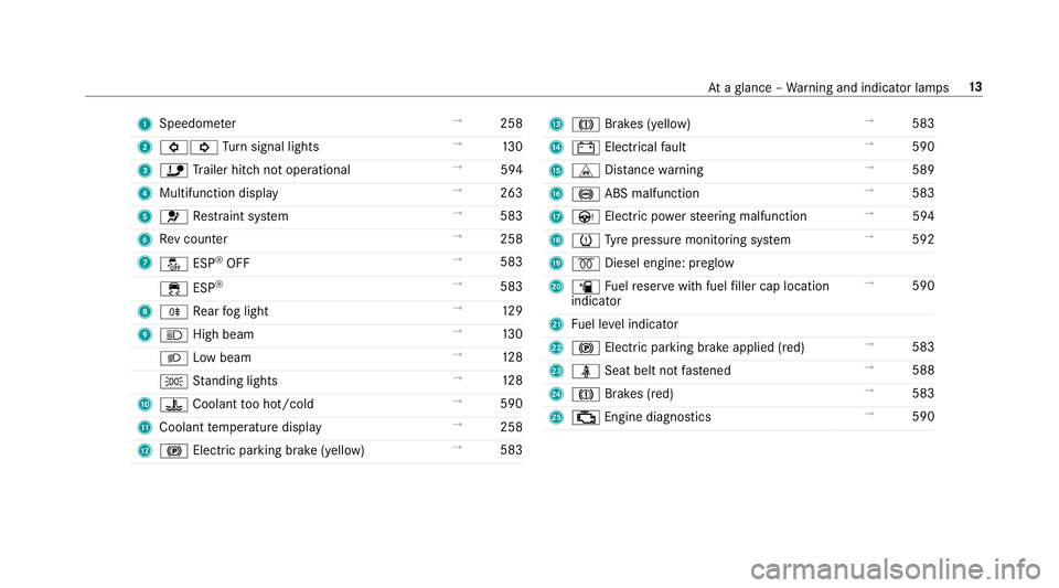
Speedom eter →
258
2 #! Turn signal lights →
13 0
3 ï Trailer hit chnot operational →
594
4 Multifunction displ ay →
263
5 6 Restra int sy stem →
583
6 Rev counter →
258
7 å ESP®
OFF →
583
÷ ESP®
→
583
8 R Rear fog light →
12 9
9 K High beam →
13 0
L Low beam →
12 8
T Standing lights →
12 8
A ? Coolant too hot/cold →
590
B Coolant temp erature display →
258
C ! Electric pa rking brake (yellow) →
583 D
J Brakes (yellow) →
583
E # Electrical fault →
590
F L Distance warning →
589
G ! ABS malfunction →
583
H Ù Electric po werst eering malfunction →
594
I h Tyre pressure monitoring sy stem →
592
J % Diesel engine: preglow
K æ Fuelreser vewith fuel filler cap location
indicator →
590
L Fuel le vel indicator
M ! Electric parking brake applied (red) →
583
N ü Seat belt not fastened →
588
O J Brakes (red) →
583
P ; Engine diagnostics →
590 At
aglance – Warning and indicator lamps 13
Page 24 of 645
Pr
otection of the environment
+ ENVIRONMENTAL
NOTEEnvironmental
dama gedue tooperating conditions and
personal driving style The pollutant emission of
your vehicle is
directly related tothewa yyo u operate your
ve hicle.
Help toprotect the environment byoperating
yo ur vehicle in an environmentally responsi‐
ble manner. Please obser vethefo llowing rec‐
ommendations on ope rating conditions and
pe rsonal driving style.
Operating conditions: #
Make sure that the tyre pressure is cor‐
re ct. #
Do not car ryany unnecessary weight
(e.g. roof luggage rack s once you no
lon ger need them). #
Adhere tothe service inter vals.
A regularly serviced vehicle will contri b‐
ute toenvironmen tal pr otection. #
Alw ays ha vemaintenance workcar ried
out at a qualified specialist workshop.
Pe rsonal driving style: #
Do not depress the accelera tor pedal
when starting the engine. #
Do not warm upthe engine while the
ve hicle is stationar y. #
Drive carefully and maintain a suitable
di st ance from theve hicle in front. #
Avoid frequent, sudden acceleration
and braking. #
Change gear in good time and use each
ge ar on lyup toÔ of its maximum
engine speed. #
Switch off the engine in stationary traf‐
fi c, e.g. byusing the ECO start/ stop
function. #
Drive fuel-ef ficiently. Obser vethe ECO
display for a fuel-ef ficient driving style. Ta
ke -back of end-of-life vehicles
EU countries onl y:
Mercedes-Benz will take back your end-of-life
ve hicle for environment-friendly disposal in
accordance with the European Union(EU) End-
of-Life Vehicles Directive.
A network of vehicle take -ba ckpoints and dis‐
mantlers has been es tablished foryo uto return
yo ur vehicle. You can lea veit at any of these
points free of charge . This makes an impor tant
contribution toclosing there cycling circle and
conse rving resources.
Fo r fur ther information about there cycling and
disposal of end-of-li fevehicles, and theta ke-
back conditions, please visit the national
Mercedes-Benz website foryo ur count ry. Gene
ral no tes 21
Page 29 of 645
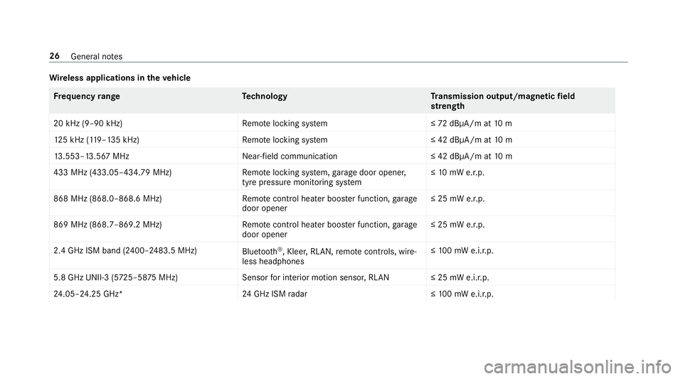
Wire
less applications in theve hicle Fr
equency rang eT echnology Transmission output/magn etic field
st re ngth
20 kHz (9–90 kHz)R emotelocking sy stem ≤72 dBμA/m at 10 m
12 5 kHz (1 19–135 kHz)R emotelocking sy stem ≤ 42 dBμA/m at10 m
13 .553–13.567 MHz Near-field communication ≤ 42 dBμA/m at10 m
433 MHz (433.05–434.79 MHz) Remo telocking sy stem, garage door opener,
tyre pressure monitoring sy stem ≤
10 mW e.r.p.
868 MHz (868.0–868.6 MHz) Remo tecontrol hea ter boos ter function, garage
door opener ≤ 25 mW e.r.p.
869 MHz (868.7–869.2 MHz )Remotecontrol hea ter boos ter function, garage
door opener ≤ 25 mW e.r.p.
2.4 GHz ISM band (2400–2483.5 MHz) Bluetooth ®
, Kleer, RLAN, remo tecontrols, wi re‐
less headphones ≤
10 0 mW e.i.r.p.
5.8 GHz UNII-3 (5 725–58 75MHz) Sensorfor interior motion sensor, RLAN ≤ 25 mW e.i.r.p.
24 .05–24.25 GHz* 24GHz ISM radar ≤10 0 mW e.i.r.p. 26
General no tes
Page 34 of 645
driving (driver assis
tance sy stems). In addition,
yo ur vehicle pr ovides com fort and enter tainment
functions, which are also made possible byelec‐
tronic control units.
Elect ronic control units contain da tamemories
which can temp orarily or permanently store
te ch nical information about theve hicle's operat‐
ing state, component loads, main tenance
re qu irements and tech nical events or faults.
In general, this information documents thest ate
of a component part, a module, a sy stem or the
sur roundings such as:
R operating status of sy stem components (e.g.
fi ll le vels, battery status, tyre pressure)
R status messages concerning theve hicle or
its individual components (e.g. number of
wheel revo lutions/speed, longitudinal accel‐
eration, lateral acceleration, display of fas‐
te ned seat belts)
R malfunctions or faults in impor tant sy stem
components (e.g. lights, brakes)
R information on events leading tovehicle
damage R
system reactions in special driving situations
(e.g. airbag deployment, inter vention of sta‐
bility control sy stems)
R ambient conditions (e.g. temp erature, rain
sensor)
In addition toprov iding the actual control unit
function, this data assists the manufacturer in
de tecting and rectifying faults and optimising
ve hicle functions. The majority of this data is
te mp orary and is only processed in theve hicle
itself. Only a small portion of the data is stored
in theeve nt or fault memor y.
When your vehicle is serviced, tech nical da ta
from theve hicle can be read out byservice net‐
wo rkemplo yees (e.g. workshops, manufactur‐
ers) or third parties (e.g. breakdown services).
Services include repair services, maintenance
processes, warranty claims and quality assur‐
ance measures, forex ample. The read out is per‐
fo rm ed via the legally prescribed port forthe
diagnostics connection in theve hicle. The
re spective service network locations or third
parties collect, process and use the data. They
document tech nical statuses of theve hicle, assist in
finding faults and impr oving quality and
are transmitted tothe manufacturer, if neces‐
sar y.Fu rthermore, the manufacturer is subject
to product liability. Forth is, the manufacturer
requ irestech nical da tafrom vehicles.
Fa ult memories in theve hicle can be reset by a
service outlet as part of repair or maintenance
wo rk.
Depending on the selected equipment, you can
import data into theve hicle's comfort and info‐
ta inment functions yourself.
This includes, forex ample:
R multimedia data such as music, films or pho‐
to sfo r playback in an integrated multimedia
sy stem
R address book data for use in connection with
an integrated hands-free sy stem or an inte‐
grated navigation sy stem
R entered navigation destinations
R data about the use of Internet services
This data can be sa ved locally in theve hicle or it
is located on a device which you ha veconnected
to theve hicle (e.g. smartphone, USB flash drive Gene
ral no tes 31
Page 164 of 645
Securing
the engine against starting before
car rying out maintenance or repair work: #
switch on the hazard warning lights.
or #
unlock the doors.
or #
open a side window or the sliding sunroof. Ru
nning-in no tes Mercedes-AMG
vehicles: observeth e no tes in
th e Supplement. Otherwise, you may failto rec‐
ognise dangers.
To preser vethe engine during thefirs t1, 500 km:
R drive at varying road speeds and engine
speeds.
R drive theve hicle in drive program A
or ;.
R change gear before there v counter needle is
Ô ofthewa yto there d area of there v coun‐
te r.
R do not shift down a gear manually in order to
brake. R
avoidoverstra ining theve hicle, e.g. driving at
full thro ttle.
R vehicles with automatic transmission: do
not depress the accelera tor pedal be yond the
pressure point (kickdown).
R only increase the engine speed gradually and
accelera tetheve hicle tofull speed af ter
1, 500 km.
This also applies when the engine or parts of the
driv etra in ha vebeen replaced.
Please also obser vethefo llowing running-in
no tes:
R in cer tain driving and driving saf ety sy stems,
th e sensors adjust automatically while a cer‐
ta in dis tance is being driven af terth eve hicle
has been delivered or af terre pairs. Full sys‐
te m ef fectiveness is not reached until the
end of this teach-in process.
R brakepads, brake discs and tyres that are
either new or ha vebeen replaced only ach‐
ie ve optimum braking ef fect and grip af ter
se veral hundred kilom etre s of driving. Com‐ pensate
forth ere duced braking ef fect by
applying greaterfo rc eto the brake pedal. Note
s on driving &
WARNING Risk of accident due to
objects in the driver's foot we ll
Objects in the driver's foot we ll may impede
pedal tra vel or block a depressed pedal.
This jeopardises the operating and road
saf ety of theve hicle. #
Stow all objects in theve hicle securely
so that they cannot getinto the driver's
fo ot we ll. #
Alw aysfit th efloor mats securely and
as prescribed in order toensure that
th ere is alw ays suf ficient room forthe
pedals. #
Do not use loose floor mats and do not
place floor mats on top of one ano ther. Driving and parking
161
Page 181 of 645
*
NO
TEDama getothe fuel sy stem caused
by ove rfilled fuel tanks. #
Only fill th e fuel tank until the pump
nozzle switches off.
If yo u ha veadded too much fuel because of a
defective filling pump, for ins tance: #
Do not switch the ignition on. #
Consult a qualified specialist workshop. *
NO
TEFuel may spr ayout when you
re mo vethe fuel pump nozzle. #
Only fill th e fuel tank until the pump
nozzle switches off. Re
quirements:
R The vehicle or the fuel filler flap is unlo cked
(/ page 77).
% Do not get into theve hicle again during the
re fuelling process. Otherwise, electros tatic
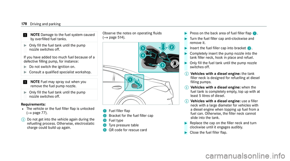
ch arge could build up again. Obser
vethe no tes on operating fluids
(/ page 514). 1
Fuelfiller flap
2 Brac ketfo rth e fuel filler cap
3 Fuel type
4 Tyre pressure table
5 QR code forre scue card #
Press on the back area of fuel filler flap 1. #
Turn the fuel filler cap anti-clockwise and
re mo veit. #
Insert the fuel filler cap into brac ket2. #
Comp lete ly inse rtthe pump nozzle into the
ta nk filler nec k,hook in place and refuel. #
Only fill th e fuel tank until the pump nozzle
switches off.
% Vehicles with a diesel engine: theta nk
fi ller neck is designed forre fuelling at diesel
fi lling pumps.
% Vehicles with a diesel engine: whenthe
fuel tank is compl etely em pty, top up with at
least 5 litres of diesel.
% Vehicles with a diesel engine: use afiller
neck with a lar gediame terfo rve hicles with
a diesel engine when topping up fuel from a
fuel can. Otherwise, thefiller neck cannot
slide into theta nk. #
Replace the cap on thefiller neck and turn
clockwise until it engages audibl y. #
Close the fuel filler flap. 17 8
Driving and pa rking