Page 141 of 645
#
Allow the component parts tocool
down before replacing the bulb. R
Do not use a bulb if it has been dropped or if
itsglass has been sc ratched. The bulb may
ot herwise explode.
R Do not touch theglass bulb with your bare
hands.
R Protect bulbs from moisture and do not allow
bulbs tocome into contact wi thliquids. Overview of
the bulbs tobe changed Halogen headlamps
1
Main beam: H7 55 W bulb
2 Dipped beam: H7 55 W bulb Ta
il lamps 1
Turn signal indicator: PY 21W bulb 13 8
Light and sight
Page 142 of 645

Changing
the front bulbs (vehicles with halo‐
ge n headla mps) Fi
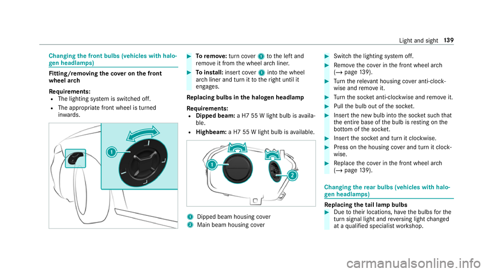
tting/ removing the co ver on the front
wheel ar ch
Re quirements:
R The lighting sy stem is switched off.
R The appropriate front wheel is turned
in wa rds. #
Toremo ve:turn co ver1 tothe left and
re mo veit from the wheel ar chliner. #
Toinstall: insert co ver1 into the wheel
ar ch liner and turn it totheright until it
engages.
Re placing bulbs in the halo gen headla mp
Re quirements:
R Dipped beam: a H7 55 W light bulb is availa‐
ble.
R Highbeam: a H7 55 W light bulb is available. 1
Dipped beam housing co ver
2 Main beam housing co ver #
Switch the lighting sy stem off. #
Remo vethe co ver in the front wheel ar ch
( / page 139). #
Turn there leva nt housing co ver anti-clock‐
wise and remo veit. #
Turn the soc ket anti-clo ckwise and remo veit. #
Pull the bulb out of the soc ket. #
Inse rtthe new bulb into the soc ket su chthat
th e entire base of the bulb is resting on the
bottom of the soc ket. #
Inse rtthe soc ket and turn it clo ckwise. #
Press on the housing co ver and turn it clock‐
wise. #
Replace the co ver in the front wheel ar ch
( / page 139). Changing
there ar bulbs (vehicles with halo‐
ge n headla mps) Re
placing the tail lamp bulbs #
Due totheir locations, ha vethe bulbs forthe
turn signal light and reve rsing light changed
at a qualified specialist workshop. Light and sight
13 9
Page 636 of 645

Live
Traf fic Information ....................... 368
Overview ............................................. 367
Re gis tering Live Traf fic Information ..... 368
Switching on the display ......................3 70
Tr af fic map
see Map
Tr af fic Sign Assist .................................. .244
Fu nction/no tes ................................... 24 4
Setting ................................................. 24 6
Sy stem limitations ...............................2 44
Tr ailer hitch
Axle load ............................................. 526
Bicycle rack ......................................... 255
Ca re .................................................... 458
Coupling up/uncoupling a trailer ........ 254
Fa stening points ..................................5 24
Fo lding the ball neck out/in ................2 52
Gene ral no tes ...................................... 524
Mounting dimensions .......................... 524
No tes .................................................. 252
Overhang dimension ............................5 24
Soc ket ................................................. 254
To ngue weight .................................... .526
To wing capacity .................................. .525 Tr
ailer operation
Ac tive Blind Spot Assi st....................... 24 8
Ac tive Lane Keeping Assist .................. 24 9
Bicycle rack ......................................... 255
Coupling up/uncoupling a trailer ........ 254
Fo lding the ball neck out/in ................2 52
No tes .................................................. 252
Soc ket ................................................. 254
Tr ailer stabilisation
Fu nction/no tes ................................... 19 6
Tr ansfer redve hicle data
Android Auto ....................................... 409
Apple CarPl ay™ ................................... 409
Baidu CarLife ....................................... 409
Tr ansmission (problem) ..........................174
Tr ansmission position display ................17 0
Tr anspo rting
Ve hicle .................................................4 79
Tr im element (Care) ................................ 460
Tr ip
Menu (on-board computer) .................. 265
Tr ip computer
Displaying ............................................ 265 Re
setting ............................................. 266
Tr ip distance ............................................ 265
Displaying ............................................ 265
Re setting ............................................. 266
Tr ip me ter
see Trip dis tance
Tu rn signal indicator
see Turn signal lights
Tu rn signal lights .....................................1 30
Changing bulbs (rear) .......................... 13 9
Switching on/off ................................. 13 0
Tw o phone mode
see Second telephone
Tw o-w ayradios
Fr equencies ......................................... 511
No tes on ins tallation ............................ 51 0
Tr ansmission output (maximum) .......... 511
Ty re inflation compressor
see TIREFIT kit
Ty re pressure ........................................... 487
Checking (ty repressure monitoring
sy stem) ............................................... 488
No tes .................................................. 486 Index
633