2019 MASERATI QUATTROPORTE light
[x] Cancel search: lightPage 342 of 396

bottle does not drop when the
engine cools, the cooling system
should be tested by an Authorized
Maserati Dealer .
• Keep the front of the radiator and
the condenser clean.
WARNING!
• Never add engine coolant
(antifreeze) when the engine is hot.
Do not loosen or remove the cap of
the engine coolant bottle to cool a
hot engine. Heat causes pressure to
build up in the cooling system. To
prevent scalding or injury, do not
remove the pressure cap while the
system is hot or under pressure.
• When adding coolant do not use a
pressure cap other than the one
specified for your vehicle. Personal
injury or engine damage may result.
WARNING!
California Proposition 65
Operating, servicing and maintaining
a passenger vehicle or off-road vehicle
can expose you to chemicals including
such as, engine exhaust, carbon
monoxide, phthalates and lead, that which are known to the State of
California to cause cancer and birth
defects or other reproductive harm. To
minimize exposure, avoid breathing
exhaust, do not idle the engine except
as necessary, service your vehicle in a
well-ventilated area and wear gloves
or wash your hands frequently when
servicing your vehicle. For more
information go to:
www.P65Warnings.ca.gov/passenger-
vehicle
Brake Fluid Level Check
Check
the fluid level immediately if
the brake system warning light
and the related message turn on
indicating a low level of brake fluid.
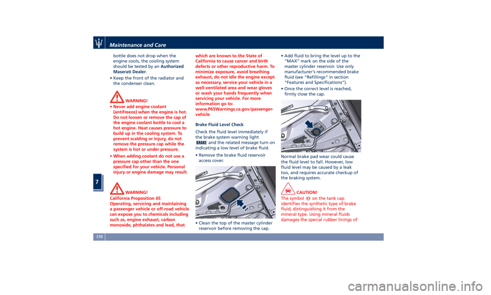
• Remove the brake fluid reservoir
access cover.
• Clean the top of the master cylinder
reservoir before removing the cap. • Add fluid to bring the level up to the
“MAX” mark on the side of the
master cylinder reservoir. Use only
manufacturer's recommended brake
fluid (see “Refillings” in section
“Features and Specifications”).
• Once the correct level is reached,
firmly close the cap.
Normal brake pad wear could cause
the fluid level to fall. However, low
fluid level may be caused by a leak
too, and requires accurate checkup of
the braking system.
CAUTION!
The symbol
on the tank cap
identifies the synthetic type of brake
fluid, distinguishing it from the
mineral type. Using mineral fluids
damages the special rubber linings ofMaintenance and Care
7
338
Page 343 of 396

the brake system irreparably.
WARNING!
• To avoid contamination from foreign
materials or moisture, use only new
brake fluid or fluid that has been in
a tightly closed container. Keep the
master cylinder reservoir cap
secured at all times.
• Overfilling the brake fluid reservoir
can result in spilling brake fluid.
Brake fluid can also damage painted
and vinyl surfaces, make sure it does
not spill over these surfaces.
• Do not allow petroleum based fluid
to contaminate the brake fluid.
Brake seal components could be
damaged.
Adding Washer Fluid
The
reservoir on
the left side of the
engine compartment contains the
fluid to wash the windshield.
During scheduled services or when the
message of low level of the washer
fluid appears together with the
related telltale
add more fluid as
soon as possible.
The fluid reservoir may contain nearly
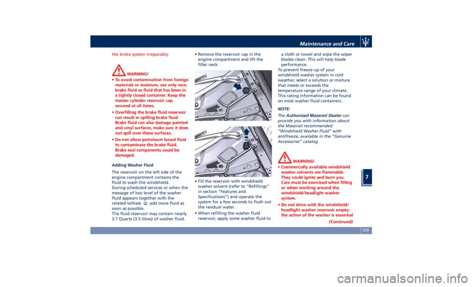
3.7 Quarts (3.5 litres) of washer fluid. • Remove the reservoir cap in the
engine compartment and lift the
filler neck.
• Fill the reservoir with windshield
washer solvent (refer to “Refillings”
in section “Features and
Specifications”) and operate the
system for a few seconds to flush out
the residual water.
• When refilling the washer fluid
reservoir, apply some washer fluid to a cloth or towel and wipe the wiper
blades clean. This will help blade
performance.
To prevent freeze-up of your
windshield washer system in cold
weather, select a solution or mixture
that meets or exceeds the
temperature range of your climate.
This rating information can be found
on most washer fluid containers.
NOTE:
The Authorized Maserati Dealer can
provide you with information about
the Maserati recommended
“Windshield Washer Fluid” with
antifreeze, available in the “Genuine
Accessories” catalog.
WARNING!
• Commercially available windshield
washer solvents are flammable.
They could ignite and burn you.
Care must be exercised when filling
or when working around the
windshield/headlight washer
system.
• Do not drive with the windshield/
headlight washer reservoir empty:
the action of the washer is essential
(Continued)Maintenance and Care
7
339
Page 344 of 396

(Continued)
for improving visibility when
driving.
WARNING!
California Proposition 65
Operating, servicing and maintaining
a passenger vehicle or off-road vehicle
can expose you to chemicals including
such as, engine exhaust, carbon
monoxide, phthalates and lead, that
which are known to the State of
California to cause cancer and birth
defects or other reproductive harm. To
minimize exposure, avoid breathing
exhaust, do not idle the engine except
as necessary, service your vehicle in a
well-ventilated area and wear gloves
or wash your hands frequently when
servicing your vehicle. For more
information go to:
www.P65Warnings.ca.gov/passenger-
vehicle
Engine Oil Level Check
T
o assure
proper lubrication of your
vehicle's engine, the engine oil must
be maintained at the correct level.
If the
warning light illuminates
and the related message of low oil
level displays, or during scheduled services (see “Scheduled Maintenance
Service” in this section) it is necessary
to check the engine oil level.
The best time to check the engine oil
level is about five minutes after a fully
warmed up engine is shut off or
before starting the engine after it has
sat overnight. In both cases the vehicle
should be parked on level ground to
improve the accuracy of the oil level
readings.
CAUTION!
• Do not top up with oil with different
characteristics than the engine one
(refer to “Refillings” in section
“Features and Specifications”).
• Overfilling or underfilling the oil pan
will cause aeration or loss of oil
pressure. This could damage your
engine.
• Do not add any supplemental
materials to the engine oil. Engine
oil is an engineered product, and its
performance may be impaired by
supplemental additives.
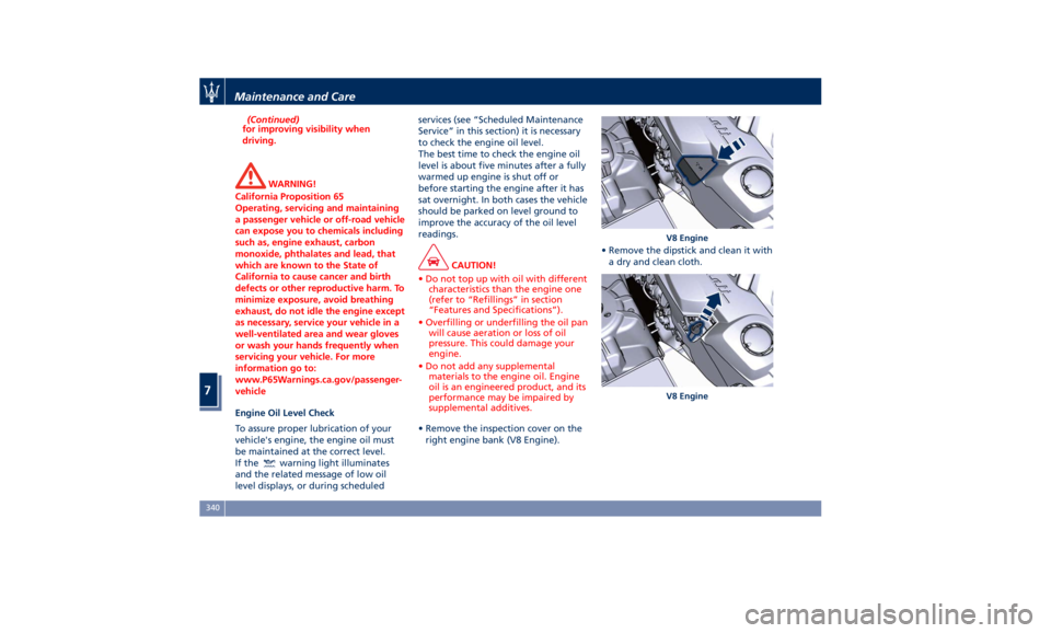
• Remove the inspection cover on the
right
engine bank
(V8 Engine). • Remove the dipstick and clean it with
a dry and clean cloth. V8 Engine
V8 EngineMaintenance and Care
7
340
Page 350 of 396

time. Then move the lid
automatically, using the buttons on
the lid itself, performing a complete
cycle of opening and closing.
• Initialize the climate control system
by activating the system and pressing
the “AUTO” control as described in
chapter “Air Conditioning Controls”
in section “Dashboard Instruments
and Controls”.
• Turn on the MTC+ and set the date
and time (see “MTC+ Settings” in
section “Dashboard Instruments and
Controls”).
• Lift, release and lift again the lever
on the central console to initialize
the electric parking brake. Following
this operation the
warning light
on the instrument cluster will turn
off.
• For correct activation of the
approach lights on the external
mirrors, press at least once the tilt
button on the driver's door panel so
that the door mode recognizes the
mirrors position.
• If the car is equipped with power
sunshades on rear door windows,
carry out the self learning cycle
described on chapter “Power
Sunshades on Rear Door Windows”
in section “Before Starting”. CAUTION!
• Every time the battery is
reconnected, wait at least 30 seconds
with the ignition switch turned to
RUN before starting the engine, in
order to allow the electronic system
that manages the motor-driven
throttles to run a self-learning cycle.
At the same time, you can run the
date and time set up procedure for
the MTC+.
• Every time the battery is reconnected
the warning light
flash for about
10 seconds and then go off.
WARNING!
California Proposition 65
Operating, servicing and maintaining
a passenger vehicle or off-road vehicle
can expose you to chemicals including
such as, engine exhaust, carbon
monoxide, phthalates and lead, that
which are known to the State of
California to cause cancer and birth
defects or other reproductive harm. To
minimize exposure, avoid breathing
exhaust, do not idle the engine except
as necessary, service your vehicle in a
well-ventilated area and wear gloves or wash your hands frequently when
servicing your vehicle. For more
information go to:
www.P65Warnings.ca.gov/passenger-
vehicle
Useful Advice to Extend
Battery Life When parking the vehicle, make sure
that the doors, front, rear lids and
flaps are properly closed. All interior
lights should be off.
When the engine is turned off, do not
keep the connected devices switched
on for a long time (such as radio,
hazard warning flashers, fan, etc.).
CAUTION!
If the battery charge remains below
50% for a long period of time, it will
be damaged due to sulfation; its
performance and starting power will
be reduced and it will be more subject
to freezing.
We recommend you to have the
battery
charge condition
checked,
preferably at the beginning of the cold
season, to prevent the electrolyte from
freezing.
This check should be carried out more
frequently if the vehicle is used mainlyMaintenance and Care
7
346
Page 355 of 396

Ref. Type Function
9––
10 – –
11 Mini – 20A Horn relay input
12 Mini – 10A AC compressor
feed relay input
13 – –
14 Mini – 7,5A Alarm siren
15 Mini – 10A Washer heated
nozzles relay
input
16 Mini – 10A Enable cooling
fan relay input
and enable
cooling oil pump
relay input
18 – –
19 – –
20 Maxi – 30A Wiper motor
relay output
21 – –
22 – –
23 – –
24 – –
28 Mini – 7,5A Driver Assist
System Module
(DASM) Ref. Type Function
29 Mini – 10A PCM
module-Starter
solenoid relay
coil
30 Mini – 5A ORC - Air bag
module
31 Mini – 5A ABS-ESP module
32 Mini – 5A SSCU, AWD
module (AWD
version only), EPS
and AQS
33 Mini – 10A HDLP LED
Headlights
34 Mini – 15A Primary load to
engine harness
LH side
35 Mini – 15A Primary load to
engine harness
RH side
36 Mini – 30A PCM module
primary load
37 Mini – 15A Engine secondary
load
38 Mini – 15A Lambda sensor Ref. Type Function
39 Mini – 7,5A Flow meters,
tank lackage,
canister, exhaust
by-pass valve
relay coil and air
shutter
48 – –
49 Mini – 10A Pedal brake
switch-TCM
module
50 Mini – 15A +30 PCM module
51 Mini – 30A Fuel pump relay
input
52 Mini – 5A Starter solenoid
signal for PCM
and voltage
stabilizer
53 Mini – 10A AWD module
(AWD version
only)Maintenance and Care
7
351
Page 357 of 396

Ref. Type Function
23 Mini – 10A Fuel door relay
and RF Hub
module
24 Mini – 10A ITM module,
ceiling light unit
(front and rear),
rain/lights sensor
25 Mini – 20A Inverter Ref. Type Function
26 – –
27 Mini – 20A LH rear seat
movement
31 Mini – 25A LH front seat
movement
32 – –
33 Mini – 20A RH rear seat
movement Ref. Type Function
34 Mini – 20A Soft Door Close
latch
35 Mini – 20A Rear doors
sunshade
36 Mini – 10A Transmission
lever, TPMS
module, Navtrak,
Hands Free access
module and
ASBM control
suspension
37 Mini – 25A Power
liftigate/trunk lid
module
38 Mini – 25A RH front seat
movement
40 Maxi – 20A Trunk power
outlet
41 – –
42 – –
43 Mini – 20A Seat passenger
heater module
44 – –
45 – –
46 Mini – 5A Rear camera
47 Mini – 5A Navtrak
48 Mini – 5A Surround viewMaintenance and Care
7
353
Page 358 of 396

Ref. Type Function
49 Mini – 10A Internal
temperature
sensor, internal
mirror and HALF
50 – –
51 Mini – 25A Rear seat and
steering wheel
heater module
52 – –
53 Mini – 25A Rear seat vented
module
54 Mini – 7,5A Blind Spot
module
55 – –
56 Mini – 7,5A Blower front
HVAC coil relay
57 Mini – 7,5A Blower rear
HVAC coil relay
58 – –
59 Mini – 10A SDC module,
transmission
lever, ASBM, rear
tunnel stack
switch
60 Mini – 10A SDC module Ref. Type Function
61 Mini – 25A Front console
power outlet and
cigar lighter
62 Mini – 7,5A Front HVAC
module
63 Mini – 20A Blower rear
HVAC
64 Mini – 10A Wi-fi, rear HVAC
module
65 Mini – 10A Intelligent
battery sensor
66 Mini – 10A Wi-fi, RSE
67 Mini – 7,5A USB charge
outlet, sunroof
68 Mini – 20A Rear sunshade
module
69 Mini – 25A Rear console
power outlet and
cigar lighter
70 Mini – 10A Front HVAC
module and
Parking Aid
Module (PAM)Fuse Box under the Dashboard This box is located in an internal area
that can be accessed only by removing
the glove compartment on the
dashboard left side. Considering the
complexity of this operation, we
recommend having the fuses replaced
by an Authorized Maserati Dealer .
The table points out the position as
featured in the figure, the type and
function of the fuses in the box under
the dashboard.
Ref. Type Function
1 Mini – 7,5A Cluster module,
CSS, SGW and
DSRC - Japan
version
2 Mini – 15A Cluster module,
clock
3 Mini – 10A DSRC and DTV
system (Japan
version only)
4 Mini – 5A E-call
5 Mini – 7,5A Security Gateway
6 Mini – 25A Radio
7 Mini – 10A Column software
module, CSS, USB
auxiliary portMaintenance and Care
7
354
Page 359 of 396

Ref. Type Function
8 Mini – 10A Start & Stop
switch,
diagnostic outlet
Bulb Replacement The signal failure of an external light
(turn signal, low beam and high beam,
number plate light, reverse light and
brake light) is communicated to the
instrument cluster that displays on the
TFT screen in a graphical form and
with a text message which light is
faulty (see example in the figure).
Front Headlights The lights are arranged as follows:
1 Low-beam/high-beam LED.
2 Position and DRL light LED.
3 Direction indicator LED.
4 Side-marker light LED.
5 Side reflex-reflector.
6 Bending light LED.Maintenance and Care
7
355