2019 MASERATI LEVANTE light
[x] Cancel search: lightPage 154 of 436

open, then adjust the sunroof opening
to minimize the buffeting.
Ignition Off Operation The power sunroof controls will
remain active for up to approximately
ten minutes after the ignition switch is
in OFF position. Opening either front
door will cancel this feature. The
ignition system timing can be set using
the MTC+ System (see “MTC+ Settings”
in section “Dashboard Instruments and
Controls”).
Sunroof Maintenance Use only a nonabrasive cleaner and a
soft cloth to clean the glass panel. HomeLink ®
(optional) HomeLink ®
replaces up to three
hand-held transmitters operating the
automatic devices that open garage
doors and gates, enable/disable the
lighting or security systems. The
HomeLink ®
unit is powered by your
vehicle's 12 Volt battery. The
HomeLink ®
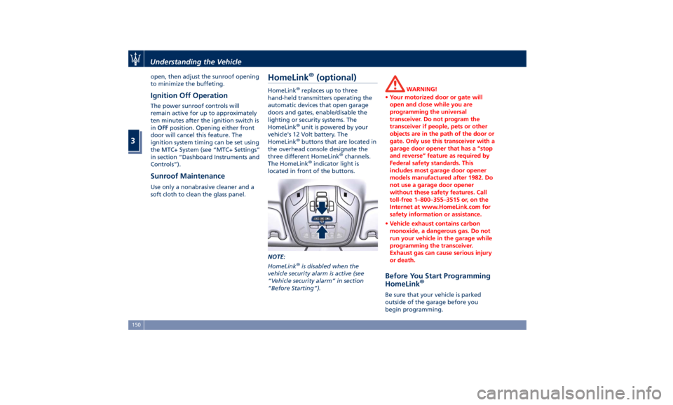
buttons that are located in
the overhead console designate the
three different HomeLink ®
channels.
The HomeLink ®
indicator light is
located in front of the buttons.
NOTE:
HomeLink ®
is disabled when the
vehicle security alarm is active (see
“Vehicle security alarm” in section
“Before Starting”). WARNING!
• Your motorized door or gate will
open and close while you are
programming the universal
transceiver. Do not program the
transceiver if people, pets or other
objects are in the path of the door or
gate. Only use this transceiver with a
garage door opener that has a “stop
and reverse” feature as required by
Federal safety standards. This
includes most garage door opener
models manufactured after 1982. Do
not use a garage door opener
without these safety features. Call
toll-free 1–800–355–3515 or, on the
Internet at www.HomeLink.com for
safety information or assistance.
• Vehicle exhaust contains carbon
monoxide, a dangerous gas. Do not
run your vehicle in the garage while
programming the transceiver.
Exhaust gas can cause serious injury
or death.
Before You Start Programming
HomeLink ®
Be sure that your vehicle is parked
outside of the garage before you
begin programming.Understanding the Vehicle
3
150
Page 155 of 436

For more efficient programming and
accurate transmission of the
radio-frequency signal it is
recommended that a new battery be
placed in the hand-held transmitter of
the device that is being programmed
to the HomeLink ®
system.
Before starting programming it is
necessary to erase the standard codes
memorized on the HomeLink ®
device
during the production phase. To erase
such codes:
• place the ignition device in the RUN
position without starting the engine;
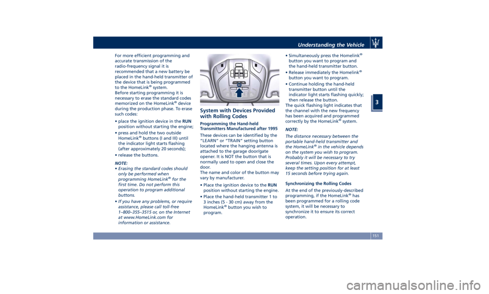
• press and hold the two outside
HomeLink ®
buttons (I and III) until
the indicator light starts flashing
(after approximately 20 seconds);
• release the buttons.
NOTE:
• Erasing the standard codes should
only be performed when
programming HomeLink ®
for the
first time. Do not perform this
operation to program additional
buttons.
• If you have any problems, or require
assistance, please call toll-free
1–800–355–3515 or, on the Internet
at www.HomeLink.com for
information or assistance. System with Devices Provided
with Rolling Codes Programming the Hand-held
Transmitters Manufactured after 1995
These devices can be identified by the
“LEARN” or “TRAIN” setting button
located where the hanging antenna is
attached to the garage door/gate
opener. It is NOT the button that is
normally used to open and close the
door.
The name and color of the button may
vary by manufacturer.
• Place the ignition device to the RUN
position without starting the engine.
• Place the hand-held transmitter 1 to
3 inches (5 - 30 cm) away from the
HomeLink ®
button you wish to
program. • Simultaneously press the Homelink ®
button you want to program and
the hand-held transmitter button.
• Release immediately the Homelink ®
button you want to program.
• Continue holding the hand-held
transmitter button until the
indicator light starts flashing quickly;
then release the button.
The quick flashing light indicates that
the channel with the new frequency
has been acquired and programmed
correctly by the HomeLink ®
system.
NOTE:
The distance necessary between the
portable hand-held transmitter and
the HomeLink ®
in the vehicle depends
on the system you wish to program.
Probably it will be necessary to try
several times. Upon every attempt,
keep the setting position for at least
15 seconds before trying again.
Synchronizing the Rolling Codes
At the end of the previously-described
programming, if the HomeLink ®
has
been programmed for a rolling code
system, it will be necessary to
synchronize it to ensure its correct
operation.Understanding the Vehicle
3
151
Page 156 of 436

• Locate the “LEARN” or “TRAINING”
setting button of the opening motor.
Firmly press it and then release it. On
some garage door openers/devices
there may be a light that blinks
when the garage door opener/device
is in the LEARN/TRAIN mode.
NOTE:
You have 30 seconds to initiate the
next step after the setting button has
been pressed.
• Return to the vehicle and press the
programmed HomeLink ®
button for
two seconds and then release it.
• Repeat this operation a second time.
If the garage door opening device
activates, the programming/
synchronization phase is complete.
NOTE:
If the garage door opening device
does not activate, press the button a
third time for two seconds and then
release it to complete the
programming/synchronization phase.
• To program the remaining two
HomeLink ®
buttons, repeat the same
step for each remaining button. DO
NOT erase the channels. Reprogramming a Single HomeLink ®
Button
To reprogram a channel that has been
previously trained, follow these steps:
• Place the ignition device to the RUN
position without starting the engine.
• Press and hold the desired
HomeLink ®
button.
• Without releasing the button
proceed with “Programming the
hand-held transmitters” from second
step and follow all remaining steps.
System with Devices Without
Rolling Code Programming the Hand-held
Transmitters Manufactured before
1995
• Turn the ignition device to the RUN
position without starting the engine.
• Place the hand-held transmitter 1 to
3 inches (5 to 30 cm) away from the
HomeLink ®
button you wish to
program.
• Simultaneously press and hold both
buttons until the indicator light
starts flashing quickly; then release
both buttons.
The quick flashing light indicates that
the channel with the new frequency has been acquired and programmed
correctly by the HomeLink ®
system.
NOTE:
The distance necessary between the
portable hand-held transmitter and
the HomeLink ®
in the vehicle depends
on the system you wish to program.
Probably it will be necessary to try
several times. Upon every attempt,
keep the setting position for at least
15 seconds before trying again.
• Press and hold the programmed
HomeLink ®
button.
If the garage door opener/device
activates, programming is complete. To
program the remaining two
HomeLink ®
buttons, repeat each step
for the same remaining button. Do not
erase the channels.
Reprogramming a Single HomeLink ®
Button
To reprogram a channel that has been
previously trained, follow these steps:
• Place the ignition device to the RUN
position without starting the engine.
• Press and hold the desired
HomeLink ®
button.
• Without releasing the button
proceed with “Programming theUnderstanding the Vehicle
3
152
Page 157 of 436

hand-held transmitters” from second
step and follow all remaining steps.
Using HomeLink ®
To operate, press and release the
programmed HomeLink ®
button.
Activation will now occur for the
programmed device (i.e., garage door
opener, gate operator, security system,
entry door lock, home/office lighting,
etc.). The hand-held transmitter of the
device may also be used at any time.
Security It is advisable to erase all channels
before you sell or turn in your vehicle.
To erase the channels press and hold
the two outside HomeLink ®
buttons (I
and III) until the indicator light starts
flashing (after approximately 20
seconds).
The HomeLink ®
Universal Transceiver
is disabled when the vehicle security
alarm is active (see “Vehicle security
alarm” in section “Before Starting”).
Troubleshooting Tips If you are having trouble while
programming HomeLink ®
, here are
some of the most common solutions:
• Replace the battery in the original
hand-held transmitter. • Press the LEARN button on the
garage door opener to complete the
training for a rolling code.
• Did you unplug the device for
programming and forgot to plug it
back in?
If you have any problems, or require
assistance, please call toll-free
1–800–355–3515 or, on the Internet at
www.HomeLink.com for information
or assistance.
Radio Frequency Device -
Regulatory Information The “Regulatory Information” for all
the radio frequency and radar devices
can be consulted by accessing the
"Services" section on the website
www.maserati.com. Understanding the Vehicle
3
153
Page 164 of 436

Instrument Cluster The instrument cluster is divided into
three main areas displaying
information, signs and text and/or icon
messages.
A Analogue speedometer. It
indicates the vehicle speed.
B Rev Counter.
C TFT display. In this area the
odometer display shows the
total distance covered by the
vehicle.
U.S. Federal Regulations requires that
upon transfer of vehicle ownership,
the seller certify to the purchaser the
correct mileage that the vehicle has
been driven.
If your odometer needs to be repaired
or serviced, the repair technician
should leave the odometer reading the
same as it was before the repair or
service. This repair should be
performed by an Authorized Maserati
Dealer .
The odometer setting should be
maintained following the repair or
service.
Keep a record of the odometer
mileage before any repair or service to ensure that the odometer is properly
reset.
Speedometer and Rev Counter display
the main warning lights (see “Warning
and Indicator Lights on Analogue
Instruments” in this chapter).
The other warning and indicator lights
are displayed on the TFT display
together with mode and drive
function indicators (see “TFT Display: Warning/Indicator Lights of Set
Modes/Functions” in this chapter).
NOTE:
The image shows the instrument
cluster before starting the engine.
V8 Engine (in example GTS version)
V6 EngineDashboard Instruments and Controls
4
160
Page 165 of 436

Warning and Indicator Lights
on Analog Instruments Telltales on Speedometer
The following telltales are displayed
on the speedometer, and related
messages are visible for 5 seconds on
the central sector of the display, unless
otherwise indicated (see “TFT Display:
Warning/Indicator Lights of Set
Modes/Functions” paragraph in this
chapter).
Malfunction Indicator Light (MIL)
The Malfunction Indicator
Light (MIL) is part of an
onboard diagnostic system
that monitors engine and
automatic transmission control
systems.
Under normal conditions, this
indicator light should switch on when
the ignition switch is in RUN position and switch off soon after the engine is
started (the MIL does not shut off
immediately).
This is a sign of the indicator light
working properly. If the indicator
remains illuminated or switches on
while driving, there is a failure in the
fuel supply/ignition and emission
control systems.
The failure could cause high exhaust
emissions, loss of performance, poor
vehicle handling and high
consumption levels.
Should this occur, proceed with
caution to your Authorized Maserati
Dealer without heavy throttle
application or driving at high speeds.
Obey all applicable local traffic
regulations.
The indicator light will go out if the
problem is no longer present.
The error will be registered by the
system in any case.
CAUTION!
• When the ignition switch is in the
RUN position and if the indicator
light does not switch on or if it
switches on while driving, contact an
Authorized Maserati Dealer as soon
as possible. • Prolonged driving with the MIL on
could cause damage to the engine
control system. It also could affect
fuel economy and drivability. If the
MIL is flashing, severe catalytic
converter damage and power loss
will soon occur. Immediate service is
required. In addition, the OBDII
system incorporates a diagnostic
connector that can be interfaced
using diagnostic equipment. This
makes it possible to read the error
codes stored in the control unit,
together with a set of specific
parameters for the engine operation
diagnostic cycle, for compliance with
CARB & EPA OBDII regulations.
Left Turn Signal Indicator Light
The
indicator lights up when
the left turn signals or the
hazard flashers are turned on.
The indicator light will flash at
the same frequency of the turn signals
and is controlled by the multifunction
lever behind the steering wheel.
If the vehicle electronics sense that the
vehicle drives for more than 1 mile
(1.6 km) with either turn signal on, a
continuous sound will alert the driver
to turn the signal off.Dashboard Instruments and Controls
4
161
Page 166 of 436

If the indicator flashes at a rapid rate,
check for a defective exterior light
bulb.
Tire Pressure Monitoring Light
This warning light is connected
to the Tire Pressure
Monitoring System (TPMS).
Under normal conditions, the
warning light should illuminate when
the ignition switch is in RUN and
should go off once the engine is
started.
If the warning light remains lit or
illuminates while driving, the pressure
of one or more tires is too low and a
message will be displayed.
The TPMS malfunction warning light is
connected to the low tire pressure
monitoring light.
When the system detects a
malfunction, the monitoring light and
the related message will flash for
approximately one minute and then
remain lit.
This sequence will continue upon
subsequent vehicle startups as long as
the malfunction lasts.
When the malfunction warning lights
up, the system may not be able to
detect or signal low tire pressure
correctly. Please refer to “Tire Pressure
Monitoring System (TPMS)” in section
“Driving” for further information.
Anti-Lock Braking System (ABS)
Malfunction Warning Light
This light, and its related
message, indicate possible
malfunctions of the Anti-Lock
Brake System (ABS).
The light will turn on when the
ignition switch is in RUN position and
may stay on for 4 seconds. If the ABS
light remains lit or turns on while
driving, the Anti-Lock portion of the
brake system is not functioning and
requires service. However, the
conventional brake system will
continue to operate normally if the
warning light is switched off. If
the ABS light turns on while driving, or
if it does not switch on when the
ignition switch is in RUN position,
please visit an Authorized Maserati
Dealer as soon as possible to restore
the Anti-Lock brake function.
Electronic Stability Control (ESC)
Activation/Malfunction Indicator Light
The ESC activation/malfunction
indicator light on the
instrument cluster will display
when the ignition switch is in
RUN position. It should switch off by starting the
engine.
If the light stays on with the engine
running, there is a malfunction in the
ESC system.
If the light still stays on after several
ignition cycles, and the vehicle has
been driven for several miles at more
than 30 mph (48 km/h) speed, visit an
Authorized Maserati Dealer as soon as
possible to have the problem
diagnosed and serviced.
NOTE:
Each time the ignition switch is in RUN :
• The ESC OFF indicator light
and
the ESC activation/malfunction
indicator light illuminates
temporarily.
• When the ESC is functioning, the
system will make buzzing or clicking
sounds. This is normal. The sounds
will stop once ESC becomes inactive
and the road conditions that caused
the ESC activation no longer persist.
Electronic Stability Control (ESC) OFF
Indicator Light
This indicator notifies that the
Electronic Stability Control
(ESC) is disabled (OFF); the
linked message will be
displayed.Dashboard Instruments and Controls
4
162
Page 167 of 436

Telltales on Tachometer
Following telltales are displayed on
the tachometer and related messages
are visible for 5 seconds on the central
sector of the display, unless otherwise
indicated (see “TFT Display:
Warning/Indicator Lights of Set
Modes/Functions” in this chapter).
Start&Stop Active Indicator
This telltale indicates that the
engine has been switched off
automatically by the
Start&Stop system.
When the engine starts again, the
telltale will switch off.
If the telltale during an automatic
engine shutdown (AutoStop) phase
starts flashing, it will be necessary to
restart the engine normally with the
ignition device while holding down
the brake pedal. See chapter “Automatic Start&Stop
System” in section “Driving” for
further information.
Rear Fog Light Indicator
This indicator lights up when
the rear fog lights are
switched on.
High Beam Indicator
This indicator lights up when
the high beams are switched
on or when blinking.
Brake Indicator Light
This light monitors various
brake functions, including
brake fluid level, brake pads
wear and parking brake
engagement.
If the brake light illuminates the
parking brake may be engaged, the
brake pads have reached wear limit,
the brake fluid level may be low or a
problem with the anti-lock brake
system (ABS) reservoir may have
occurred.
In all the above situations, a related
message will be displayed.
If the light still illuminates when the
parking brake has been disengaged,
and the fluid level is at the full mark
on the master cylinder reservoir, there
could be a brake hydraulic system malfunction or a problem with the
brake booster detected by the
ABS/ESC system. If this occurs, the light
will remain lit until the problem has
been solved.
If the problem concerns the brake
booster, the ABS master cylinder will
run when engaging the brake and a
brake pedal pulsation may be felt
during each stop of the vehicle.
Inefficiency of one of the dual brake
system cycles is indicated by the brake
indicator light, which will turn on
when the brake fluid level in the
master cylinder has dropped below a
certain level.
The light will remain lit until the
problem has been solved.
If a brake failure occurs, visit an
Authorized Maserati Dealer as soon as
possible in order to check up the
brake system.
In the event of an Electronic Brake
Force Distribution (EBD) failure, both
the brake indicator light and the ABS
light illuminate.
Immediate repair of the ABS system is
required.
Functioning of the brake indicator
light can be checked by turning the
ignition switch from OFF to RUN
position.Dashboard Instruments and Controls
4
163