2019 MASERATI LEVANTE spare tire
[x] Cancel search: spare tirePage 357 of 436
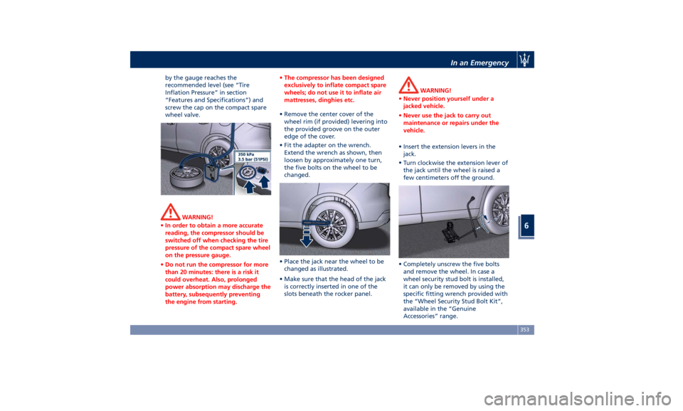
by the gauge reaches the
recommended level (see “Tire
Inflation Pressure” in section
“Features and Specifications”) and
screw the cap on the compact spare
wheel valve.
WARNING!
• In order to obtain a more accurate
reading, the compressor should be
switched off when checking the tire
pressure of the compact spare wheel
on the pressure gauge.
• Do not run the compressor for more
than 20 minutes: there is a risk it
could overheat. Also, prolonged
power absorption may discharge the
battery, subsequently preventing
the engine from starting. • The compressor has been designed
exclusively to inflate compact spare
wheels; do not use it to inflate air
mattresses, dinghies etc.
• Remove the center cover of the
wheel
rim (if provided) levering into
the provided groove on the outer
edge of the cover.
• Fit the adapter on the wrench.
Extend the wrench as shown, then
loosen by approximately one turn,
the five bolts on the wheel to be
changed.
• Place the jack near the wheel to be
changed as illustrated.
• Make sure that the head of the jack
is correctly inserted in one of the
slots beneath the rocker panel. WARNING!
• Never position yourself under a
jacked vehicle.
• Never use the jack to carry out
maintenance or repairs under the
vehicle.
• Insert the extension levers in the
jack.
•
Turn clockwise
the extension lever of
the jack until the wheel is raised a
few centimeters off the ground.
• Completely unscrew the five bolts
and remove the wheel. In case a
wheel security stud bolt is installed,
it can only be removed by using the
specific fitting wrench provided with
the “Wheel Security Stud Bolt Kit”,
available in the “Genuine
Accessories” range.In an Emergency
6
353
Page 358 of 436
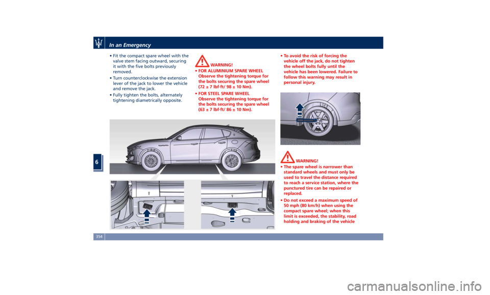
• Fit the compact spare wheel with the
valve stem facing outward, securing
it with the five bolts previously
removed.
• Turn counterclockwise the extension
lever of the jack to lower the vehicle
and remove the jack.
• Fully tighten the bolts, alternately
tightening diametrically opposite. WARNING!
• FOR ALUMINIUM SPARE WHEEL
Observe the tightening torque for
the bolts securing the spare wheel
(72 ± 7 lbf·ft/ 98 ± 10 Nm).
• FOR STEEL SPARE WHEEL
Observe the tightening torque for
the bolts securing the spare wheel
(63 ± 7 lbf·ft/ 86 ± 10 Nm). • To avoid the risk of forcing the
vehicle off the jack, do not tighten
the wheel bolts fully until the
vehicle has been lowered. Failure to
follow this warning may result in
personal injury.
WARNING!
• The spare wheel is narrower than
standard wheels and must only be
used to travel the distance required
to reach a service station, where the
punctured tire can be repaired or
replaced.
• Do not exceed a maximum speed of
50 mph (80 km/h) when using the
compact spare wheel; when this
limit is exceeded, the stability, road
holding and braking of the vehicleIn an Emergency
6
354
Page 359 of 436
will be compromised. Avoid
accelerating to full speed, heavy
braking and fast cornering.
• The compact spare wheel must be
inflated to the recommended tire
pressure (see “Tire Inflation
Pressure” in section “Features and
Specifications”).
• For safety reasons, it is absolutely
forbidden to drive with more than
one compact spare wheel fitted on
the vehicle.
• Snow chains cannot be fitted on the
compact spare wheel.
• The spare wheel can travel a
maximum of 1,800 mi (3.000 km).
To Refit the Standard Wheel with
Repair
ed or Replaced Tire
• Following the procedure and the
caution described above, raise the
vehicle and remove the compact
spare wheel reusing the supplied
wrench with adapter, suitably
extended.
• Fit the standard wheel with repaired
or replaced tire.
• Tighten the original bolts on the
wheel.
• Lower the vehicle and remove the
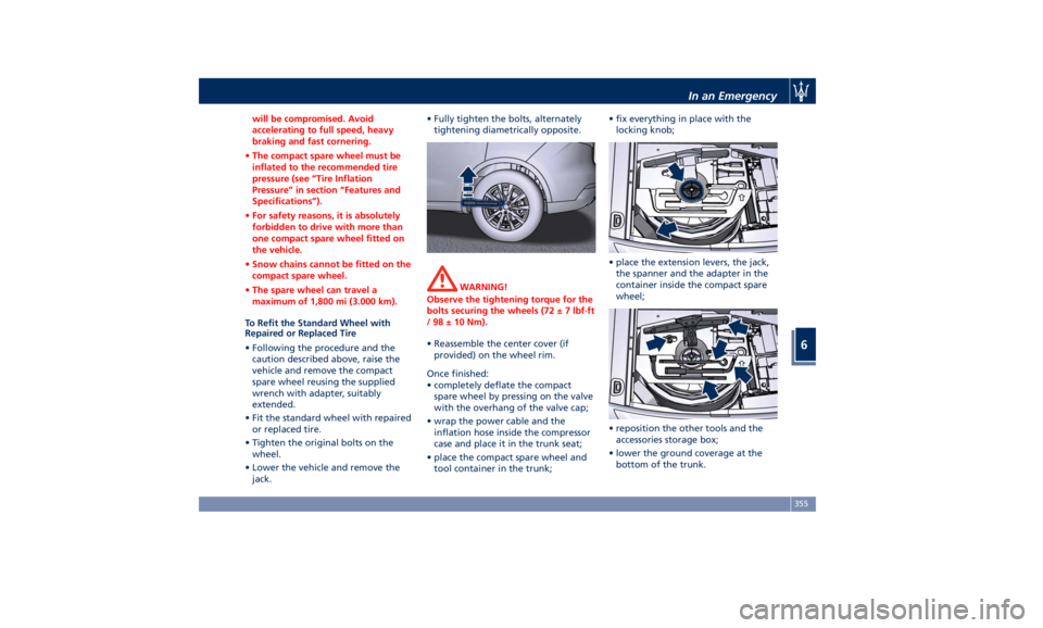
jack. • Fully tighten the bolts, alternately
tightening diametrically opposite.
WARNING!
Observe the tightening torque for the
bolts securing the wheels (72 ± 7 lbf·ft
/ 98 ± 10 Nm).
• Reassemble the center cover (if
provided)
on the wheel
rim.
Once finished:
• completely deflate the compact
spare wheel by pressing on the valve
with the overhang of the valve cap;
• wrap the power cable and the
inflation hose inside the compressor
case and place it in the trunk seat;
• place the compact spare wheel and
tool container in the trunk; • fix everything in place with the
locking knob;
• place the extension levers, the jack,
the spanner and the adapter in the
container inside the compact spare
wheel;
• reposition the other tools and the
accessories storage box;
• lower the ground coverage at the
bottom of the trunk.In an Emergency
6
355
Page 370 of 436

Main Operations/Service Coupons Interval running coupons: every 12,500 mi (20,000 km)
or 1 year
Service coupons 1° 2° 3° 4°
5° 6°
Main operations Available Pre-Paid Maintenance
Program
Vehicle road test III
Check with Maserati Diagnosi IIIIII
Engine oil and filter RRRRRR
Engine coolant level IIIIII
Engine check for leaks IIIIII
Cooling system connections and lines (check for leaks) III
Air filter R
Belt for alternator, water pump and air conditioning
compressor (3.8 V8 engine) IIIRII
Replace every time the part is removed
Belt for alternator (1) and belt for water pump and air
conditioning compressor (3.0 V6 engine) IIIRII
Replace every time the part is removed
Spark plugs RR
Intercooler check for leaks IIIIII
Brake fluid IIIIII
Replace every 2 years
Brake system (lines, calipers, connections) - Instrument cluster
warning light efficiency - Parking brake operation IIIIII
Tire wear, tire and spare tire (if equipped) pressure check IIIIII
Joints, rods for front and rear suspensions, front and rear
under-chassis IIIMaintenance and Care
7
366
Page 417 of 436
Wheels NOTE:
• Maserati recommends Maserati Genuine Tires marked with “MGT” logo specifically designed for its models.
• In order to maintain high performance and safety level, Maserati recommends to use tires equivalent to the original
size.
• Optionally tires may have "ZR" in the size description combined with speed index (e.g. 265/45 ZR20 104Y).
• In case of staggered tires, front and rear rims cannot be swapped.
• Only 19” rear tires can be equipped with special chain with front anchorage. Snow chains cannot be used (all tires).
WARNING!
• The maximum speed reachable with the tires is indicated by the tire manufacturer. Always comply with the regulations
in force in the Country you are driving in.
• Never exceed the maximum speed indicated for the tires: failure to respect the max. speed may damage these tires.
Danger: risk of accident!
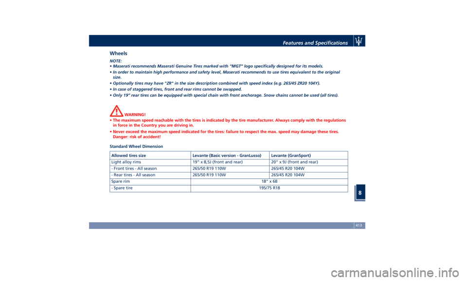
Standard Wheel Dimension
Allowed tires size Levante (Basic version - GranLusso) Levante (GranSport)
Light alloy rims 19” x 8,5J (front and rear) 20” x 9J (front and rear)
- Front tires - All season 265/50 R19 110W 265/45 R20 104W
- Rear tires - All season 265/50 R19 110W 265/45 R20 104W
Spare rim 18” x 6B
- Spare tire 195/75 R18Features and Specifications
8
413
Page 418 of 436
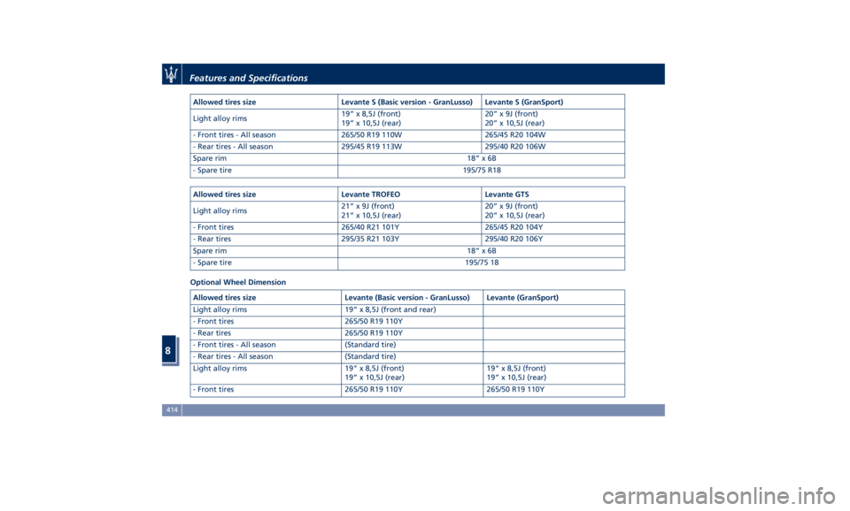
Allowed tires size Levante S (Basic version - GranLusso) Levante S (GranSport)
Light alloy rims 19” x 8,5J (front)
19” x 10,5J (rear) 20” x 9J (front)
20” x 10,5J (rear)
- Front tires - All season 265/50 R19 110W 265/45 R20 104W
- Rear tires - All season 295/45 R19 113W 295/40 R20 106W
Spare rim 18” x 6B
- Spare tire 195/75 R18
Allowed tires size Levante TROFEO Levante GTS
Light alloy rims 21” x 9J (front)
21” x 10,5J (rear) 20” x 9J (front)
20” x 10,5J (rear)
- Front tires 265/40 R21 101Y 265/45 R20 104Y
- Rear tires 295/35 R21 103Y 295/40 R20 106Y
Spare rim 18” x 6B
- Spare tire 195/75 18
Optional Wheel Dimension
Allowed tires size Levante (Basic version - GranLusso) Levante (GranSport)
Light alloy rims 19” x 8,5J (front and rear)
- Front tires 265/50 R19 110Y
- Rear tires 265/50 R19 110Y
- Front tires - All season (Standard tire)
- Rear tires - All season (Standard tire)
Light alloy rims 19" x 8,5J (front)
19” x 10,5J (rear) 19" x 8,5J (front)
19” x 10,5J (rear)
- Front tires 265/50 R19 110Y 265/50 R19 110YFeatures and Specifications
8
414
Page 425 of 436
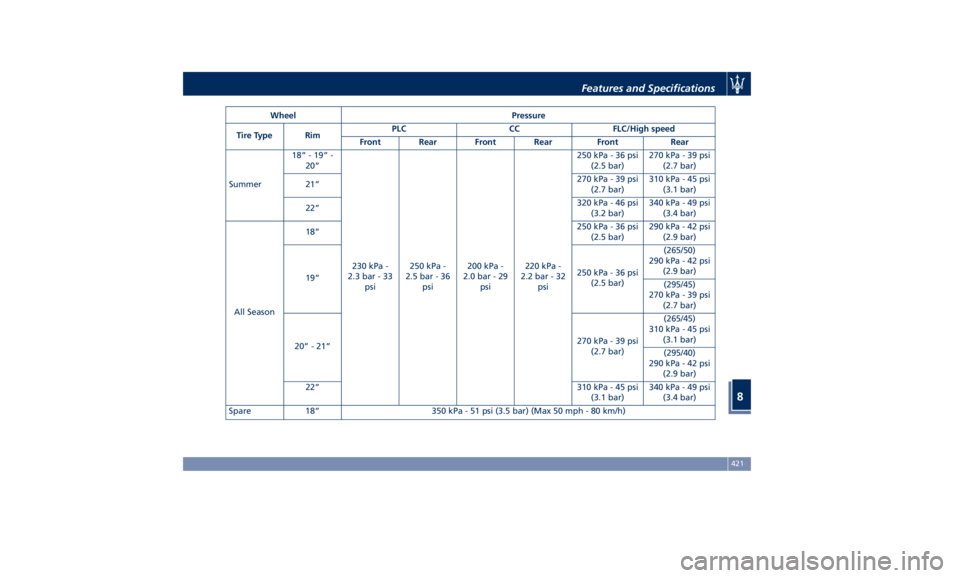
Wheel Pressure
Tire Type Rim PLC CC FLC/High speed
Front Rear Front Rear Front Rear
Summer 18” - 19” -
20”
230 kPa -
2.3 bar - 33
psi 250 kPa -
2.5 bar - 36
psi 200 kPa -
2.0 bar - 29
psi 220 kPa -
2.2 bar - 32
psi 250 kPa - 36 psi
(2.5 bar) 270 kPa - 39 psi
(2.7 bar)
21” 270 kPa - 39 psi
(2.7 bar) 310 kPa - 45 psi
(3.1 bar)
22” 320 kPa - 46 psi
(3.2 bar) 340 kPa - 49 psi
(3.4 bar)
All Season 18” 250 kPa - 36 psi
(2.5 bar) 290 kPa - 42 psi
(2.9 bar)
19” 250 kPa - 36 psi
(2.5 bar) (265/50)
290 kPa - 42 psi
(2.9 bar)
(295/45)
270 kPa - 39 psi
(2.7 bar)
20” - 21” 270 kPa - 39 psi
(2.7 bar) (265/45)
310 kPa - 45 psi
(3.1 bar)
(295/40)
290 kPa - 42 psi
(2.9 bar)
22” 310 kPa - 45 psi
(3.1 bar) 340 kPa - 49 psi
(3.4 bar)
Spare 18” 350 kPa - 51 psi (3.5 bar) (Max 50 mph - 80 km/h) Features and Specifications
8
421
Page 432 of 436

Passenger Seat Belts ..........61
Seat Belt Reminder Light ..... .164
Seat Belts and Pregnant Women . .65
Seat Belts Pretensioners ........63
Three-Point Seat Belts .........59
Three-Point Seat Belts Height
Adjustment ................61
Three-Point Seat Belts Untwisting
Procedure .................61
Three-Point Seat Belts Use
Instructions ................59
Using the Seat Belt in Automatic
Locking Retractor Mode (ALR) . . .63
Seats ......................97
Driver Memory Seat ........ .101
Easy Entry/Exit Seats ........ .102
Front Heated Seats ...........99
Front Power Seats ............97
Front Ventilated Seats ....... .100
Power Lumbar Seats ..........98
Rear Armrest ............. .104
Rear Seat Folding Seatback . . . .103
Rear Seats ............... .103
Rear Side Heated Seats ...... .104
Seat Adjustment .............98
Service .....................10
Siri Smart Personal Assistant .... .225
SmartBeam System ........... .116
Smoking Kit ................ .137
Snow Chains ............... .328
Spare parts service
Genuine Parts ..............13
Scheduled Maintenance .......13 Spare Parts Service .............13
SRS (Supplemental Restraint
System) ....................65
Start&Stop System ........... .230
Occupant Safety Function .... .232
Start&Stop Active Indicator . . . .163
Start&Stop Disable Indicator . . . .182
Start&Stop Failure Indicator
Light ................... .182
Start&Stop Function Disabling
Indicator ................ .232
Start&Stop Menu .......... .172
Start&Stop System Failure .... .234
Start the Engine
Engine Start Failure ......... .229
Engine Turn Off ........... .230
Steering Wheel .............
.108
Heated
Steering Wheel ...... .108
Phone
and Voice Controls on
Steering Wheel ............ .224
Sunroof
Initialization Procedure ...... .149
Pinch Protect Feature ....... .149
Slide Opening Sunroof ....... .148
Sunroof Maintenance ....... .150
Venting Sunroof ........... .149
Sunshades ...................48
Sun Visors ................. .137
Surround View Camera System ....87
Symbols ....................14
Danger Symbols .............14 Symbols of Prohibitions and
Compulsory Measures .........14
Tank fuel refill .............. .336
TCS (Traction Control System) .... .275
Technical Data .............. .411
Telltales
Telltales on Speedometer ..... .161
Telltales on Tachometer ...... .163
Tires
Change a Tire ............. .351
Compact spare tire ......... .329
Department of Transportation
Uniform Tire Quality Grades . . . .325
General Information ........ .321
Inflation Pressure .......... .420
Pneumatic Suspension Mode for
Wheel Change ............ .329
Punctured Tire, use ......... .351
Replacement Tires .......... .327
Tire Pressure .............. .325
Tire Pressure Checkup ....... .326
Tire Safety Information ...... .321
TPMS - Tire Pressure Monitoring
System .................. .329
Tread Wear Indicators ....... .326
Winter Tires .............. .328
ToolKit................... .348
Towing
Towing a Disabled Vehicle .... .360
Towing the Vehicle ......... .360
Use
the Vehicle Tow Hook .... .360
Vehicle Towing Conditions .... .360Index
9 428