2019 MASERATI LEVANTE dashboard
[x] Cancel search: dashboardPage 387 of 436

To Reconnect the Battery CAUTION!
• It is essential when replacing the
cables on the battery that the
positive cable is attached to the
positive post (+) and the negative
cable is attached to the negative
post (–).
• Cable clamps should be tight on the
terminal posts and free of corrosion.
After the battery has been
disconnected
and re-connected and
before starting the engine it is
necessary to proceed as follows:
• Unlock and lock the doors using one
more time the Key fob RKE
Transmitter.
• Close manually the liftgate unlock it
lid with the key fob RKE transmitter
and then lock it manually on more time. If the vehicle is equipped with
power liftgate, manually perform
the complete closure. Then move the
lid automatically, using the buttons
on the outer edge of the left trunk,
performing a complete cycle of
opening and closing.
• Initialize the climate control system
by activating the system and
pressing the “AUTO” control as
described in chapter “Air
Conditioning Controls” in section
“Dashboard Instruments and
Controls”.
• Turn on the MTC+ and set the date
and time (see “MTC+ Settings” in
section “Dashboard Instruments and
Controls”).
• Lift, release and lift again the lever
on the central console to initialize
the electric parking brake. Following
this operation the
warning light
on the instrument cluster will turn
off.
• For correct activation of the
approach lights on the external
mirrors, press at least once the tilt
button on the driver's door panel so
that the door mode recognizes the
mirrors position.
• If the car is equipped with power
sunshades on rear door windows, carry out the teach mode cycle
described on chapter “Power
Sunshades on Rear Door Windows”
in section “Before Starting”.
CAUTION!
• Every time the battery is
reconnected, wait at least 30 seconds
with the ignition switch turned to
RUN before starting the engine, in
order to allow the electronic system
that manages the motor-driven
throttles to run a self-learning cycle.
At the same time, you can run the
date and time set up procedure for
the MTC+.
• Every time the battery is
reconnected the warning light
flash for about 10 seconds and then
go off.
WARNING!
California Proposition 65
Operating, servicing and maintaining
a passenger vehicle or off-road vehicle
can expose you to chemicals including
such as, engine exhaust, carbon
monoxide, phthalates and lead, that
which are known to the State of
(Continued)Maintenance and Care
7
383
Page 391 of 436

• on the fuse and relay box located in
a covered area, under the dashboard
left side.
Integrated Power Module • To access the module it is necessary
to lift the hood (see “Hood
Operation” in section “Before
Starting”).
• To access the fuses remove the
module cover unhooking the lateral
locks as shown in the picture. The table points out the position as
featured in the figure, the type and
function of the fuses included in the
integrated power module.
CAUTION!
• After replacement, refit the
protective cover of the module.
• If you need to wash the engine
compartment, do not direct the
water for too long directly on the
module.
Ref. Type Function
2 Maxi – 50A Secondary air
pump relay input
(V8 engines only)
3––
4 Maxi – 30A Starter motor
relay input Ref. Type Function
5 Maxi – 40A ABS-ESP pump
feed
6 Maxi – 30A AWD module
relay input
7––
8 Maxi – 40A ABS-ESP valve
feed
9––
10 – –
11 Mini – 20A Horn relay input
12 Mini – 10A AC compressor
feed relay input
13 – –
14 Mini – 7,5A Alarm siren
15 Mini – 5A Washer heated
nozzles relay
input
16 Mini – 10A Enable cooling
fan relay input
and enable
cooling oil pump
relay input
18 – –
19 Maxi – 30A Headlamp
washer relay
inputMaintenance and Care
7
387
Page 393 of 436

Ref. Type Function
39 Mini – 7,5A Flow meters,
tank lackage,
canister, exhaust
by-pass valve
relay coil and air
shutter
48 – –
49 Mini – 10A Pedal brake
switch-TCM
module
50 Mini – 15A +30 PCM module
51 Mini – 30A Fuel pump relay
input
52 Mini – 5A Starter solenoid
signal for PCM
and voltage
stabilizer
53 Mini – 10A AWD module
Rear Power Distribution Center • To access the center it is necessary to
lift the ground coverage of the trunk
compartment (see chapter “Tool Kit”
in section “In an Emergency”) and
remove the storage box.
• To access the fuses, release the cover
latch shown in picture. • Press the release latch and lift the lid
from this side.
• Push the lid toward the right side to
release the indicated latches on the
unit.
The table points out the position as
featured in the figure, the type and
function of the fuses on the rear area
distribution control unit. Ref. Type Function
2 Maxi – 40A BCM module
3 Maxi – 40A BCM module
4 Maxi – 30A BCM module
5 Maxi – 30A BCM module
6 Maxi – 20A Trailer harness
(not for TROFEO
version)
7 Maxi – 30A Driver door
module
8 Maxi – 30A Passenger door
module
9 Maxi – 40A Start&Stop:
voltage
stabilizer,
dashboard
10 Maxi – 40A Start&Stop:
voltage
stabilizer, body
11 Maxi – 40A “High Premium”
stereo amplifier
unit
Maxi – 20A “Premium”
stereo amplifier
unit (1)
15 Maxi – 40A HVAC front
blower relay coilMaintenance and Care
7
389
Page 396 of 436

Fuse Box under the Dashboard This box is located in an internal area
under the dashboard left side.
Considering the complexity of this
operation, we recommend having the
fuses replaced by an Authorized
Maserati Dealer .
The table points out the position as
featured in the figure, the type and
function of the fuses in the box under
the dashboard.
Ref. Type Function
1 Mini – 7,5A Cluster module,
USB charger, CSS,
SGW and DSRC
(Japan version
only)
2 Mini – 15A Cluster module,
clock
3 Mini – 10A DSRC and DTV
system (Japan
version only)
4 Mini – 5A E-call
5 Mini – 7,5A Security Gateway
6 Mini – 15A Radio
7 Mini – 10A Column software
module, CSS Ref. Type Function
8 Mini – 10A Start & Stop
switch,
diagnostic outlet
Maintenance and Care
7
392
Page 398 of 436

CAUTION!
Due to the complexity of the
operation, for the replacement of the
light cluster bulbs/LEDs, we
recommend that you contact an
Authorized Maserati Dealer .
WARNING!
The Bi-Xenon bulbare a type of high
voltage discharge tube. High voltage
can remain in the circuit even with the
ignition switch off. Because of this,
you should not attempt to replace a
Bi-Xenon bulb yourself, but take the
vehicle to an Authorized Maserati
Dealer for service.
Besides the light clusters, a third LED
stop
light is present on the rear side of
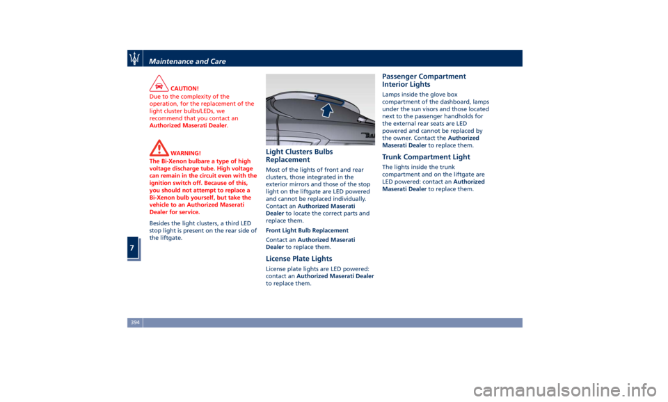
the liftgate. Light Clusters Bulbs
Replacement Most of the lights of front and rear
clusters, those integrated in the
exterior mirrors and those of the stop
light on the liftgate are LED powered
and cannot be replaced individually.
Contact an Authorized Maserati
Dealer to locate the correct parts and
replace them.
Front Light Bulb Replacement
Contact an Authorized Maserati
Dealer to replace them.
License Plate Lights License plate lights are LED powered:
contact an Authorized Maserati Dealer
to replace them. Passenger Compartment
Interior Lights Lamps inside the glove box
compartment of the dashboard, lamps
under the sun visors and those located
next to the passenger handholds for
the external rear seats are LED
powered and cannot be replaced by
the owner. Contact the Authorized
Maserati Dealer to replace them.
Trunk Compartment Light The lights inside the trunk
compartment and on the liftgate are
LED powered: contact an Authorized
Maserati Dealer to replace them.Maintenance and Care
7
394
Page 404 of 436

any other equipment such as
brushes, steel wool, abrasives or any
other equipment for cleaning.
• After cleaning, please rinse the
aluminum trim with a lot of clear
water.
• While cleaning in the car, please
make sure that the moldings and
aluminum trims only get in contact
with soft brushes or textiles.
Engine Compartment
At the end of each winter season,
carefully wash the engine
compartment, remembering to avoid
directing the jet of water for too long
on the electric parts.
To perform this operation, you must
contact an Authorized Maserati
Dealer .
Pre-Short Drop Function When in a car wash, if the driver keeps
the RKE Transmitter in his/her pocket,
or in any place outside the vehicle
within 3.3 ft (1 m) distance, the front
windows will perform a pre-short
drop. This is a shorter drop compared
to the normal short drop performed by
the “Passive Entry” function when you
grab the door handle to enter the
vehicle. In order to prevent water from
entering the vehicle between the
upper edge of the glass window and
the door outline on the bodywork,
while the car is being washed, it is
advisable to disable the “Passive
Entry” from the MTC+ System, for
further information refer to chapter
“MTC+ Settings” in section
“Dashboard Instruments and controls”.
When deactivating the “Passive Entry”,
also the “Pre-Short Drop” function will
be disabled.
Interior Maintenance and
Care Interior trim should be cleaned
starting with a damp cloth. Do not use
harsh cleaners.
The leather upholstery can be best
preserved by regular cleaning with a
damp soft cloth. Small particles of dirt
can act as an abrasive and damage the
leather upholstery and should be
removed promptly with a damp cloth.
Stubborn soils stains can be removed
easily with a soft cloth and
appropriate products. Avoid soaking
the leather upholstery with any liquid.
Please do not use polishes, oils,
cleaning fluids, solvents, detergents, or
ammonia-based cleaners to clean your
leather upholstery.
Application of a leather conditioner is
not required to maintain the original
condition.
Check at regular intervals that there is
no water trapped under the mats (due
to drips off shoes, umbrellas etc.)
which may cause the metal parts to
oxidize.
CAUTION!
Do not use alcohol, petrol or solventsMaintenance and Care
7
400
Page 429 of 436

Infants and Child Restraints .....74
Installing Child Restraint Systems
using the Vehicle Seat Belt
equipped with ALR ...........76
Lower Anchors and Tether for
Children (LATCH) ............76
Older Children and Child
Restraints .................75
Tips on getting the most out of your
child restraint ..............76
Climate Control ............. .214
Clock, analog .............. .201
Console
Central Console Components ....95
Front Dome Console
Components ...............96
Controls Screen ............. .195
Cruise Control
Cruise Control Adaptive (ACC) . .286
Electronic Cruise Control (CC) . . .282
Cupholders ................ .134
Front Passengers Cupholders . . .134
Rear Passengers Cupholders . . . .135
Dashboard Compartment ...... .210
Dashboard Components .........94
Defroster ...................91
Doors
Child Protection Door Lock
System ...................41
Doors Locking ..............39
Doors Manual Lock ...........39
Front Doors Components ......96 Lock/Unlock Door Flashlight ....34
Power Doors Locking/Unlocking . .40
Rear Doors Components .......97
Soft Door Close System ........41
Unlock Driver Door/All Doors with
Key fob 1st Press ............34
Unlock the Vehicle with Key fob. .33
DPF System
DPF Filter Replacement ...... .377
“Drive Away Inhibit” strategy . . . .272
Drive Mode, controls ......... .244
Setting Ride Height ........ .258
Setting the Drive Mode ...... .245
Driving Conditions ........... .338
Before the Trip ............ .338
Driving at Night ........... .339
Driving in Fog ............ .340
Driving in Snow and Wet Grass . .266
Driving in the Mountains ..... .340
Driving in the Rain ......... .339
Driving on Snow or Ice ...... .340
Safe Driving .............. .339
DRL (Daytime Running Light) . . . .116
EDR (Event Data Recorder) .......73
Electronic Cruise Control .......
.282
Emergency ...................
5
Hazard W arning
Lights ...... .128
In the Event of an Accident . . . .350
Jump Starting ............ .357
Use the Vehicle Tow Hook .... .360
Engine
Engine Coolant Level Check . . . .374 Engine Oil Level Check ...... .377
Hood ....................56
Normal Starting of the Engine . .228
Use of the Engine .......... .281
Entry/Exit, lights on ............30
EPB (Electric Parking Brake) ..... .268
ESC (Electronic Stability Control) . .273
Filters
A/C System Air Filter
Replacement ............. .379
Engine Air Filter Replacement . .379
Forward Collision Warning (FCW) . .297
Fuel
Carbon Monoxide Warning . . . .335
Emergency Fuel Filler Door
Release ................. .338
Emissions Inspection and
Maintenance Programs ...... .369
Fuel Consumption ......... .410
Fuel Filter Service .......... .377
Fuel Requirements ......... .334
Fuel System Warnings ....... .335
Gasoline/Oxygenate Blends . . . .334
Low Fuel Indicator ......... .181
Materials Added to Fuel ..... .335
MMT in Gasoline .......... .335
Reformulated Gasoline ...... .334
Fuses .................... .386
Fuses Position ............ .386
Fuses Replacement ......... .386
Glove Box Lock Feature ....... .211Index
9 425