2019 MASERATI LEVANTE dashboard
[x] Cancel search: dashboardPage 280 of 436

exits from this strategy when the
accelerator pedal is completely
unstuck.
Hill Start Assist (HSA) The HSA system is designed to assist
the driver when starting a vehicle
uphill. HSA will maintain the level of
brake pressure applied for a short
period of time also after releasing the
brake pedal.
If the driver does not apply the
throttle during this short period of
time, the system will release brake
pressure and the vehicle will start
sloping down. The system will release
brake pressure proportionally to the
amount of throttle/torque applied as
the vehicle starts to move in the
chosen direction.
HSA Activation Criteria
The following criteria must be met in
order for HSA to activate:
• vehicle is stationary;
• gear selection matches vehicle uphill
direction (i.e., vehicle facing uphill is
in forward gear; vehicle backing
uphill is in reverse gear).
HSA will work in R (Reverse) and all
forward gears when the activation
criteria have been met. The system will not activate if the
transmission is placed in N (Neutral) or
P (Park).
Roll-Over Mitigation (ROM) This system anticipates the potential
for wheel lift by monitoring the
driver's steering wheel input and the
speed of the vehicle. When ROM
determines that the rate of change of
the steering wheel angle and vehicle's
speed are sufficient to potentially
cause wheel lift, it then applies the
appropriate brake and may also
reduce engine power to lessen the
chance that wheel lift will occur.
ROM will only intervene during very
severe or evasive driving maneuvers.
ROM can only reduce the chance of
wheel lift occurring during severe or
evasive driving maneuvers. It cannot
prevent wheel lift due to other factors,
such as road and off-road conditions,
leaving the roadway, or striking
objects or other vehicles.
WARNING!
Many factors, such as vehicle loading,
road and off-road conditions, and
driving conditions, influence the
chance that wheel lift or rollover may occur. ROM cannot prevent all wheel
lift or roll-overs, especially those that
involve leaving the roadway or
striking objects or other vehicles. The
capabilities of a ROM-equipped
vehicle must never be exploited in a
reckless or dangerous manner, which
could jeopardize the user’s safety or
the safety of others.
Trailer Sway Mitigation (TSM) TSM uses sensors in the vehicle to
recognize an excessively swaying
trailer and will take the appropriate
actions to attempt to stop the sway.
The system may reduce engine power
and apply the brake of the
appropriate wheel(s) to counteract the
sway of the trailer. TSM will become
active automatically once an
excessively swaying trailer is
recognized.
TSM cannot stop all trailers from
swaying. Always use caution when
towing a trailer and follow the trailer
tongue weight recommendations.
Refer to “Trailer Towing” in this
section for further information. When
TSM is functioning, the “ESC
Activation/Malfunction Indicator
Light” will flash (see “Instrument
Cluster” in section “DashboardDriving
5
276
Page 285 of 436

Use of the Engine Breaking-In Today's most modern production
methods are designed to provide
extremely precise construction and
assembly of components. However,
moving parts do undergo a settling
process, basically in the first hours of
vehicle operation.
Do not drive keeping at a constant
high speed rate for a prolonged time.
While cruising, brief full-throttle
acceleration within the limits of local
traffic laws contributes to a good
break-in. Wide-open throttle
acceleration in low gear can be
detrimental and should be avoided.
The engine oil installed in the engine
at the factory is a high-quality energy
conserving type lubricant. Oil changes
should be consistent with anticipated
climate conditions under which vehicle
operations will occur. For the
recommended viscosity and quality
grades, see “Refillings” in section
“Features and Specifications”.
A new engine may consume some oil
during its first few thousand
miles/kilometers of operation. This
should be considered as a normal part of the break-in and not interpreted as
an indication of malfunction.
Specific Requirements
Avoid exceeding 5000 rpm for the first
620 mi trip (1000 km).
After starting the vehicle, do not
exceed 4000 rpm until the engine has
warmed up sufficiently (coolant
temperature: 149-158°F /65 70°).
Trailer Towing
During the first 620 mi (1000 km) of a
new vehicle it is advisable not to tow a
trailer. This allows to limit the load on
the engine and on the other parts of
the vehicle.
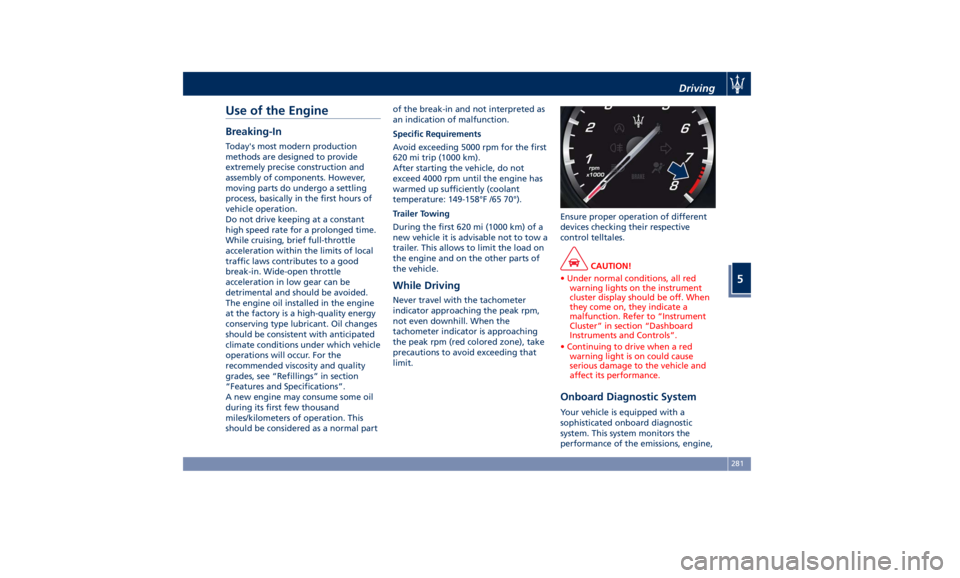
While Driving Never travel with the tachometer
indicator approaching the peak rpm,
not even downhill. When the
tachometer indicator is approaching
the peak rpm (red colored zone), take
precautions to avoid exceeding that
limit. Ensure proper operation of different
devices checking their respective
control telltales.
CAUTION!
• Under normal conditions, all red
warning lights on the instrument
cluster display should be off. When
they come on, they indicate a
malfunction. Refer to “Instrument
Cluster” in section “Dashboard
Instruments and Controls”.
• Continuing to drive when a red
warning light is on could cause
serious damage to the vehicle and
affect its performance.
Onboard Diagnostic System Your vehicle is equipped with a
sophisticated onboard diagnostic
system. This system monitors the
performance of the emissions, engine,Driving
5
281
Page 288 of 436

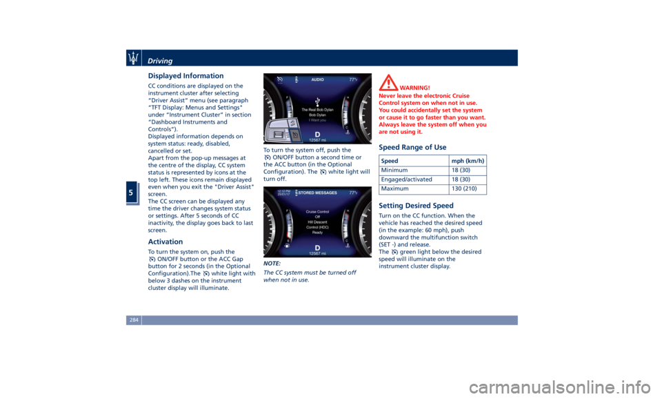
Displayed Information CC conditions are displayed on the
instrument cluster after selecting
“Driver Assist” menu (see paragraph
“TFT Display: Menus and Settings"
under “Instrument Cluster” in section
“Dashboard Instruments and
Controls”).
Displayed information depends on
system status: ready, disabled,
cancelled or set.
Apart from the pop-up messages at
the centre of the display, CC system
status is represented by icons at the
top left. These icons remain displayed
even when you exit the "Driver Assist"
screen.
The CC screen can be displayed any
time the driver changes system status
or settings. After 5 seconds of CC
inactivity, the display goes back to last
screen.
Activation To turn the system on, push the
ON/OFF button or the ACC Gap
button for 2 seconds (in the Optional
Configuration).The
white light with
below 3 dashes on the instrument
cluster display will illuminate. To turn the system off, push the
ON/OFF button a second time or
the ACC button (in the Optional
Configuration). The
white light will
turn off.
NOTE:
The CC system must be turned off
when not in use. WARNING!
Never leave the electronic Cruise
Control system on when not in use.
You could accidentally set the system
or cause it to go faster than you want.
Always leave the system off when you
are not using it.
Speed Range of Use Speed mph (km/h)
Minimum 18 (30)
Engaged/activated 18 (30)
Maximum 130 (210)
Setting Desired Speed Turn on the CC function. When the
vehicle has reached the desired speed
(in the example: 60 mph), push
downward the multifunction switch
(SET -) and release.
The
green light below the desired
speed will illuminate on the
instrument cluster display.Driving
5
284
Page 291 of 436

ahead, the ACC system automatically
kicks in by slightly accelerating or
braking (to avoid exceeding the
initially set speed) so that the vehicle
keeps present distance, trying to
adapt to the speed of the detected
vehicle ahead.
WARNING!
• The Adaptive Cruise Control (ACC) is
designed to increase vehicle driving
comfort. It must not be considered
as a means of replacing the required
attention of the driver. The driver is
always required to drive carefully.
The driver is always required to pay
utmost attention to driving
conditions (road, traffic, weather)
and style (speed, distance from
sensed vehicle ahead, brake use).
Driver has the full responsibility of
the vehicle therefore his attention is
crucial to keeping vehicle control, in
particular when approaching curves
and situations with heavy traffic.
Failure to follow these warnings can
result in a collision and death or
serious personal injury
• In some driving scenarios, the ACC
could have detection problems. In
such cases, the ACC could kick in late or unexpectedly. The driver must be
careful since his/her intervention
could be necessary.
• It is always the driver’s responsibility
to obey speed limits and to keep
minimum legal distance to the
preceding vehicle.
• ACC system can decelerate only with
limited braking, it cannot execute
emergency braking.
The ACC system:
•
Does not activate/react in the
presence of pedestrians, bicycles,
incoming traffic from opposite
direction and steady objects such as
a vehicle stuck in a traffic jam.
• Is meant for the use on highways
and well-built roads, not for city
traffic or mountain roads.
• May not have enough time to react
and/or decelerate sufficiently on
vehicles when lane is changed too
quickly or the relative speed is too
high. In such cases the driver has to
react appropriately and without any
acoustic/visual warning.
• Cannot consider road, traffic and
weather conditions and might prove
limited when visibility is poor.
• Does not always fully recognize
complex driving conditions and this could cause an incorrect assessment
of the required safety distance.
It is recommended to disable the ACC
system in the following instances:
• When driving in the fog, heavy rain,
heavy snow, slush, heavy traffic and
similar complex situations such as
highway construction zones.
• When entering a junction lane or a
slip road to leave the highway; when
driving on narrow, icy, snowy,
slippery roads, or on uphill and
downhill roads.
• The system is designed and calibrate
for car with no trailer.
• When circumstances do not allow to
drive safely at constant speed.
Displayed information Adaptive Cruise Control (ACC)
condition, as well as the LKA and HAS
status, is displayed on instrument
cluster after selecting “Driver Assist”
menu (see paragraph “TFT Display:
Menus and Settings” under
“Instrument Cluster” in section
“Dashboard Instruments and
Controls”).
Displayed information depends on
system status: ready, set, temporarily
cancelled or override.Driving
5
287
Page 305 of 436

Lane Keeping Assist - LKA
(optional, with ACC only) This system was designed especially
for highway or freeway driving, to
reduce the risk that the vehicle, under
particular circumstances, accidentally
departs from the lane in use. When
this happens, graphic instructions on
instrument cluster display together
with steering torque application and
steering wheel vibration (depending
on the distance to the line) warn the
driver that the vehicle is going out of
the lane and initiate a steering
maneuver to try to prevent the lane
exit.
To detect lane lines, the system uses
the forward-facing camera behind of
the rear-view mirror, which is the same
one used also by the lighting system
to manage the automatic high beams.
The logic core is in the front radar.
LKA system remembers the condition
it was in before turning off the
vehicle.
Refer to “MTC+ "Controls" Screen” in
section “Dashboard Instruments and
Controls” for further information. NOTE:
In case of wet road or raining
conditions the function could be
disabled by the system in order to
minimize the risks.
Speed Range of Use Speed mph (km/h)
Minimum 37 (60)
Engaged/activated 37 (60)
Maximum 112 (180)
Customized Settings LKA is configurable by the driver in
order to maximize its efficiency based
on the driver driving style and the
expectation of the system, reducing at
the same time the possible
invasiveness.
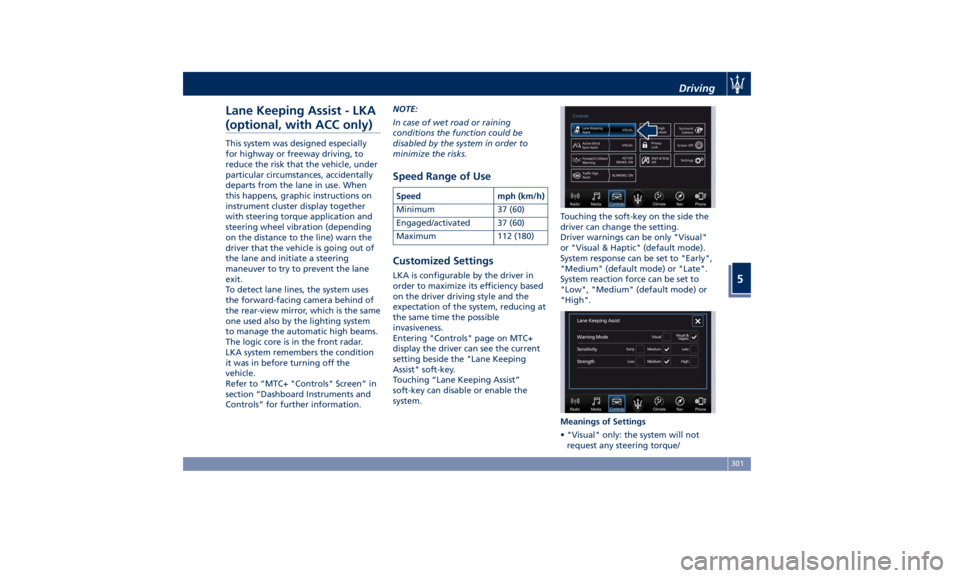
Entering "Controls" page on MTC+
display the driver can see the current
setting beside the "Lane Keeping
Assist" soft-key.
Touching “Lane Keeping Assist”
soft-key can disable or enable the
system. Touching the soft-key on the side the
driver can change the setting.
Driver warnings can be only "Visual"
or "Visual & Haptic" (default mode).
System response can be set to "Early",
"Medium" (default mode) or "Late".
System reaction force can be set to
"Low", "Medium" (default mode) or
"High".
Meanings of Settings
• "Visual" only: the system will not
request any steering torque/Driving
5
301
Page 306 of 436

vibration to correct the car trajectory.
The system will only show on the TFT
display when the vehicle is passing
the lane.
• "Visual & Haptic": the system will
apply steering torque when lane
departure is detected while showing
at the same time the proper cluster
indication, adding to this steering
vibration when the departure is very
imminent.
When "Visual & Haptic" is selected and
LKA is enabled then the following
menu will be used by the system.
• "LKA Sensitivity": it tunes the
distance to the lane boundary where
the system will start to apply steering
torque.
• "LKA Strength": it tunes the steering
torque value to have a stronger or
weaker trajectory correction/
deviation.
WARNING!
In rare cases, Lane Keeping Assist
(LKA) may make an inappropriate
steering torque application. LKA may
be interrupted at any time counter
steering. Lack of attention may lead to
serious injury or death. System Availability The ADAS systems (LKA, CC, ACC, FCW
and HAS) help the driver while driving.
These systems can be set and
monitored simultaneously on the
display, after opening “Driver Assist”
menu (see paragraph “TFT Display:
Menus and Settings” under
“Instrument Cluster” in section
“Dashboard Instruments and
Controls”).
LKA is designed for an attentive driver;
therefore the system is available only
when his/her hands are on the steering
wheel or with hands off only for a very
limited amount of time. When the
system is enabled it will trigger cluster
warning in case at least one hand is
not detected on the steering wheel.
The torque application as well as the
vibration are suppressed/inhibited in
case of: high driver torque in the
steering wheel, high lateral
acceleration, trailer connected to the
proper control module, hands not on
the steering wheel detected for more
than a certain time.
High dynamic driving behaviors,
driving on the lane boundary or
driving off course will prevent the
function from working. FCW braking
and stability system interventions (ESC, ABS) will also prevent the system from
operating. Changing lane results in
system inhibition for a certain time. In
addition, the driver must respect some
road characteristics such as
minimum-maximum width, lanes
clearly defined by two lane boundaries
and for a limited time, the presence of
at least one lane boundary.
NOTE:
• In case of wet road or raining
conditions the function could be
disabled by the system in order to
minimize the risks.
• With lane boundaries it is mainly
referred to painted lines,
nevertheless the system in good
conditions might properly recognize
as valid lane boundaries also other
types (for example road edges, curbs,
etc..).
Being this function used to prevent
unintentional lane change/lane drift, it
will be temporary suppressed/inhibited
by a turn indicator activation,
therefore, graphic warning, steering
torque application and vibration will
be terminated. In this condition in case
of a vehicle detected by the Blind Spot
Assist (BSA) system in the covered area
on the proper side, there can be theDriving
5
302
Page 312 of 436

(Continued)
• The BSA system is not designed to
detect pedestrians, cyclists, or
animals.
• Even if your vehicle is equipped with
the BSA system, always check your
vehicle’s outside and rearview
mirrors for any vehicles approaching
from behind or overtaking.
• Use your turn signal before changing
lanes.
RCP - Rear Cross Path The Rear Cross Path (RCP) feature is
intended to aid the drivers when gear
in reverse of parking spaces where
their vision of oncoming vehicles may
be blocked.
The RCP system monitors the rear
detection zones on both sides of the
vehicle. Using sensors located on either
side of the rear bumper, it detects any
vehicles or objects that are moving
toward the side of the vehicle with a
minimum speed of approximately 1 to
2 mph (1 km/h to 3 km/h) to a
maximum of approximately 10 mph
(16 km/h), such as in parking lot
situations. NOTE:
In a parking lot situation, oncoming
vehicles can be obscured by vehicles
parked on either side. If the sensors
are blocked by other structures or
vehicles, the system will not be able to
alert the driver.
Proceed slowly and cautiously out of
the parking space until the rear end of
the vehicle is moderately exposed.
The RCP system will then have a clear
view of the cross traffic. If an
oncoming vehicle is detected, the RCP
system will alert the driver using both
the visual and audible alarms. If the
radio is on, it will also reduce the radio
volume.
WARNING!
RCP is not a Back Up Aid system. More specifically, it is intended to be used to
help a driver detect an oncoming
vehicle in a parking lot situation.
Drivers must be careful when backing
up, even when using RCP. Always
check carefully behind your vehicle,
look behind you, and be sure to check
for pedestrians, animals, other
vehicles, obstructions, and blind spots
before backing up. Failure to do so can
result in serious injury or death.
BSA and RCP Setting Setting modes can be selected from
the MTC+ System.
Touch “Controls” soft-key and then
“Blind Spot Assist” soft-key to enter
the setting page.
Refer to chapter “MTC+ “Controls”
Screen” in section “Dashboard
Instruments and Controls” for further
information.Driving
5
308
Page 315 of 436

prevent the function from working.
FCW braking and stability system
interventions (ESC, ABS) will also
prevent the system from operating.
Changing lane results in system
inhibition for a certain time.
In addition the road must respect
some characteristics such as minimum-
maximum width, lane clearly defined
by two lane boundaries and only in
limited case for a limited time at least
one.
NOTE:
• In case of wet road or raining
conditions the function could be
disabled by the system in order to
minimize the risks.
• With lane boundaries it is mainly
referred to painted lines,
nevertheless the system in good
conditions might properly recognise
as valid lane boundaries also other
types (for example road edges,
curbs, etc..). Speed Range of Use Speed mph (km/h)
Minimum 37 (60)
Engaged/activated 37 (60)
Maximum 112 (180)
System Limitation Because of physical limits the system
to properly operate needs good
visibility (it might not work or not
properly operate in case of heavy rain,
snow, wet roads, fog, direct sun on
the camera, dirty windshield, low
illumination etc.)
Sharp turns, slopes and change in
slopes, poor lane boundaries, as well
as construction areas and all the
scenarios described in this paragraph
may challenge the system, therefore
be always ready to prevent any
unexpected behaviour of the car.
Damaged front bumper, windshield
replaced without proper technical
intervention may also lead to system
malfunction or system unavailability.
Other conditions such as faults, but
not explicitly indicated here may also
prevent/interrupt the system
intervention. ABSA Setting ABSA is configurable by the customer
in order to maximize its efficiency
based on the driver driving style and
his/her expectation of the system,
reducing at the same time the possible
invasiveness.
Setting modes can be selected from
the MTC+ System (see "MTC+
"Controls" Screen" in section
"Dashboard Instruments and
Controls" for further information).
Touch "Controls" soft-key to display
the current status of the ABSA system,
if it was in the on state.
To change status, touch the "Active
Blind Spot Assist" soft-key.
To change the system setting, touch
the soft-key on the side.
Driver warnings can be only "Visual",
"Visual & Acoustic" (default mode) or
"Visual & Haptic".Driving
5
311