2019 MASERATI LEVANTE warning
[x] Cancel search: warningPage 145 of 436
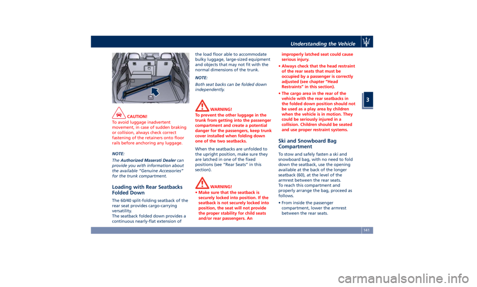
CAUTION!
To avoid luggage inadvertent
movement, in case of sudden braking
or collision, always check correct
fastening of the retainers onto floor
rails before anchoring any luggage.
NOTE:
The Authorized
Maserati Dealer can
provide you with information about
the available “Genuine Accessories”
for the trunk compartment.
Loading with Rear Seatbacks
Folded Down The 60/40 split-folding seatback of the
rear seat provides cargo-carrying
versatility.
The seatback folded down provides a
continuous nearly-flat extension of the load floor able to accommodate
bulky luggage, large-sized equipment
and objects that may not fit with the
normal dimensions of the trunk.
NOTE:
Both seat backs can be folded down
independently.
WARNING!
To prevent the other luggage in the
trunk from getting into the passenger
compartment and create a potential
danger for the passengers, keep trunk
cover installed when folding down
one of the two seatbacks.
When the seatbacks are unfolded to
the
upright position, make
sure they
are latched in one of the fixed
positions (see “Rear Seats” in this
section).
WARNING!
• Make sure that the seatback is
securely locked into position. If the
seatback is not securely locked into
position, the seat will not provide
the proper stability for child seats
and/or rear passengers. An improperly latched seat could cause
serious injury.
• Always check that the head restraint
of the rear seats that must be
occupied by a passenger is correctly
adjusted (see chapter “Head
Restraints” in this section).
• The cargo area in the rear of the
vehicle with the rear seatbacks in
the folded down position should not
be used as a play area by children
when the vehicle is in motion. They
could be seriously injured in a
collision. Children should be seated
and use proper restraint systems.
Ski and Snowboard Bag
Compartment To stow and safely fasten a ski and
snowboard bag, with no need to fold
down the seatback, use the opening
available at the back of the longer
seatback (60), at the level of the
armrest between the rear seats.
To reach this compartment and
properly arrange the bag, proceed as
follows.
• From inside the passenger
compartment, lower the armrest
between the rear seats.Understanding the Vehicle
3
141
Page 147 of 436
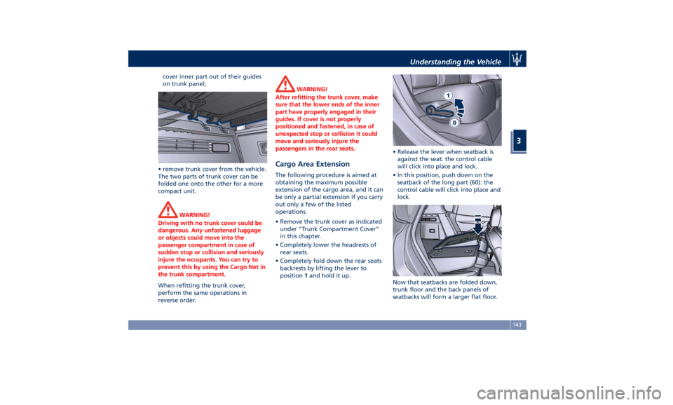
cover inner part out of their guides
on trunk panel;
• remove trunk cover from the vehicle.
The two parts of trunk cover can be
folded one onto the other for a more
compact unit.
WARNING!
Driving with no trunk cover could be
dangerous. Any unfastened luggage
or objects could move into the
passenger compartment in case of
sudden stop or collision and seriously
injure the occupants. You can try to
prevent this by using the Cargo Net in
the trunk compartment.
When refitting the trunk cover,
perform
the same operations in
reverse order. WARNING!
After refitting the trunk cover, make
sure that the lower ends of the inner
part have properly engaged in their
guides. If cover is not properly
positioned and fastened, in case of
unexpected stop or collision it could
move and seriously injure the
passengers in the rear seats.
Cargo Area Extension The following procedure is aimed at
obtaining the maximum possible
extension of the cargo area, and it can
be only a partial extension if you carry
out only a few of the listed
operations.
• Remove the trunk cover as indicated
under “Trunk Compartment Cover”
in this chapter.
• Completely lower the headrests of
rear seats.
• Completely fold down the rear seats
backrests by lifting the lever to
position 1 and hold it up. • Release the lever when seatback is
against the seat: the control cable
will click into place and lock.
• In this position, push down on the
seatback of the long part (60): the
control cable will click into place and
lock.
Now that seatbacks are folded down,
trunk floor and the back panels of
seatbacks will form a larger flat floor.Understanding the Vehicle
3
143
Page 148 of 436
CAUTION!
Seatback rear panel is not suitable to
support heavy loads and metal objects
with protruding elements that might
scratch its surface. If necessary, protect
the seatback rear panel surface using
rigid panels.
Installing the Cargo Net for
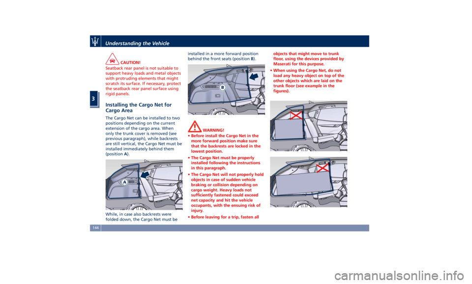
Cargo Area The Cargo Net can be installed to two
positions depending on the current
extension of the cargo area. When
only the trunk cover is removed (see
previous paragraph), while backrests
are still vertical, the Cargo Net must be
installed immediately behind them
(position A ).
While, in case also backrests were
folded down, the Cargo Net must be installed in a more forward position
behind the front seats (position B ).
WARNING!
• Before install the Cargo Net in the
more forward position make sure
that the backrests are locked in the
lowest position.
• The Cargo Net must be properly
installed following the instructions
in this paragraph.
• The Cargo Net will not properly hold
objects in case of sudden vehicle
braking or collision depending on
cargo weight. Heavy loads not
sufficiently fastened could exceed
net capacity and hit the vehicle
occupants, with the ensuing risk of
injury.
• Before leaving for a trip, fasten all objects that might move to trunk
floor, using the devices provided by
Maserati for this purpose.
• When using the Cargo Net, do not
load any heavy object on top of the
other objects which are laid on the
trunk floor (see example in the
figures).Understanding the Vehicle
3
144
Page 151 of 436
Front to Back Roof Rails
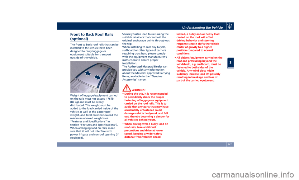
(optional) The front to back roof rails that can be
installed to this vehicle have been
designed to carry luggage or
equipment suitable for transport
outside of the vehicle.
Weight of luggage/equipment carried
on the rails must not exceed 176 lb
(80 kg) and must be evenly
distributed. This weight must be
added to the load carried inside of the
vehicle as well as the passengers'
weight, and total must not exceed the
maximum allowed weight (see
“Features and Specifications” in
section “Features and Specifications”).
When arranging load on rails, make
sure that it will not interfere with
power liftgate and sunroof opening (if
equipped). Securely fasten load to rails using the
suitable retainers that can hold the
original anchorage points throughout
the trip.
When installing to rails any bicycle,
surfboard or other types of carriers
requiring cross bars, please comply
with the equipment manufacturer's
instructions to ensure proper
installation.
The Authorized Maserati Dealer can
provide you with any information
about the Maserati approved Carrying
Items, available in the "Genuine
Accessories" range.
WARNING!
• During the trip, it is recommended
to periodically check the proper
fastening of luggage or equipment
carried on the roof rails. This is to
avoid that any parts that may have
accidentally unfastened could
damage vehicle bodywork and fall
out, thereby becoming a danger for
all vehicles behind yours.
• When driving with a bulky load on
roof rails, take additional
precautions and drive at lower
speed, keeping a wider safety
distance from vehicles ahead. Indeed, a bulky and/or heavy load
carried on the roof will affect
driving behavior and steering
response since it shifts the vehicle
center of gravity to a higher
position compared to normal
conditions.
• All objects/equipment carried on the
roof and protruding beyond the
windshield, e.g. surfboard, must be
fastened to both sides of the
vehicle. Any wind blow might
suddenly increase load lift possibly
resulting in breakage and loss of
part of the carried equipment.Understanding the Vehicle
3
147
Page 152 of 436
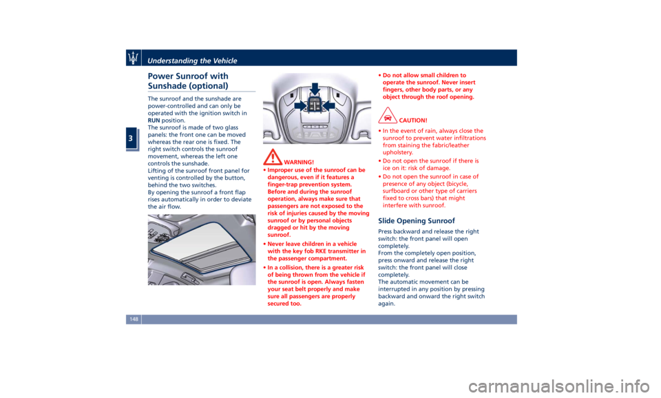
Power Sunroof with
Sunshade (optional) The sunroof and the sunshade are
power-controlled and can only be
operated with the ignition switch in
RUN position.
The sunroof is made of two glass
panels: the front one can be moved
whereas the rear one is fixed. The
right switch controls the sunroof
movement, whereas the left one
controls the sunshade.
Lifting of the sunroof front panel for
venting is controlled by the button,
behind the two switches.
By opening the sunroof a front flap
rises automatically in order to deviate
the air flow. WARNING!
• Improper use of the sunroof can be
dangerous, even if it features a
finger-trap prevention system.
Before and during the sunroof
operation, always make sure that
passengers are not exposed to the
risk of injuries caused by the moving
sunroof or by personal objects
dragged or hit by the moving
sunroof.
• Never leave children in a vehicle
with the key fob RKE transmitter in
the passenger compartment.
• In a collision, there is a greater risk
of being thrown from the vehicle if
the sunroof is open. Always fasten
your seat belt properly and make
sure all passengers are properly
secured too. • Do not allow small children to
operate the sunroof. Never insert
fingers, other body parts, or any
object through the roof opening.
CAUTION!
• In the event of rain, always close the
sunroof to prevent water infiltrations
from staining the fabric/leather
upholstery.
• Do not open the sunroof if there is
ice on it: risk of damage.
• Do not open the sunroof in case of
presence of any object (bicycle,
surfboard or other type of carriers
fixed to cross bars) that might
interfere with sunroof.
Slide Opening Sunroof Press backward and release the right
switch: the front panel will open
completely.
From the completely open position,
press onward and release the right
switch: the front panel will close
completely.
The automatic movement can be
interrupted in any position by pressing
backward and onward the right switch
again.Understanding the Vehicle
3
148
Page 154 of 436
open, then adjust the sunroof opening
to minimize the buffeting.
Ignition Off Operation The power sunroof controls will
remain active for up to approximately
ten minutes after the ignition switch is
in OFF position. Opening either front
door will cancel this feature. The
ignition system timing can be set using
the MTC+ System (see “MTC+ Settings”
in section “Dashboard Instruments and
Controls”).
Sunroof Maintenance Use only a nonabrasive cleaner and a
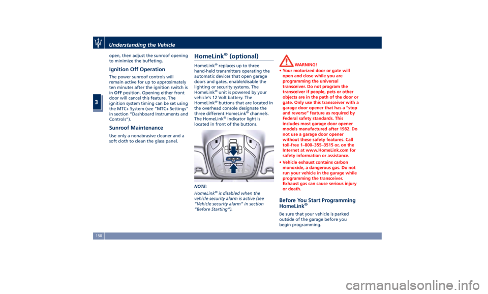
soft cloth to clean the glass panel. HomeLink ®
(optional) HomeLink ®
replaces up to three
hand-held transmitters operating the
automatic devices that open garage
doors and gates, enable/disable the
lighting or security systems. The
HomeLink ®
unit is powered by your
vehicle's 12 Volt battery. The
HomeLink ®
buttons that are located in
the overhead console designate the
three different HomeLink ®
channels.
The HomeLink ®
indicator light is
located in front of the buttons.
NOTE:
HomeLink ®
is disabled when the
vehicle security alarm is active (see
“Vehicle security alarm” in section
“Before Starting”). WARNING!
• Your motorized door or gate will
open and close while you are
programming the universal
transceiver. Do not program the
transceiver if people, pets or other
objects are in the path of the door or
gate. Only use this transceiver with a
garage door opener that has a “stop
and reverse” feature as required by
Federal safety standards. This
includes most garage door opener
models manufactured after 1982. Do
not use a garage door opener
without these safety features. Call
toll-free 1–800–355–3515 or, on the
Internet at www.HomeLink.com for
safety information or assistance.
• Vehicle exhaust contains carbon
monoxide, a dangerous gas. Do not
run your vehicle in the garage while
programming the transceiver.
Exhaust gas can cause serious injury
or death.
Before You Start Programming
HomeLink ®
Be sure that your vehicle is parked
outside of the garage before you
begin programming.Understanding the Vehicle
3
150
Page 164 of 436

Instrument Cluster The instrument cluster is divided into
three main areas displaying
information, signs and text and/or icon
messages.
A Analogue speedometer. It
indicates the vehicle speed.
B Rev Counter.
C TFT display. In this area the
odometer display shows the
total distance covered by the
vehicle.
U.S. Federal Regulations requires that
upon transfer of vehicle ownership,
the seller certify to the purchaser the
correct mileage that the vehicle has
been driven.
If your odometer needs to be repaired
or serviced, the repair technician
should leave the odometer reading the
same as it was before the repair or
service. This repair should be
performed by an Authorized Maserati
Dealer .
The odometer setting should be
maintained following the repair or
service.
Keep a record of the odometer
mileage before any repair or service to ensure that the odometer is properly
reset.
Speedometer and Rev Counter display
the main warning lights (see “Warning
and Indicator Lights on Analogue
Instruments” in this chapter).
The other warning and indicator lights
are displayed on the TFT display
together with mode and drive
function indicators (see “TFT Display: Warning/Indicator Lights of Set
Modes/Functions” in this chapter).
NOTE:
The image shows the instrument
cluster before starting the engine.
V8 Engine (in example GTS version)
V6 EngineDashboard Instruments and Controls
4
160
Page 165 of 436

Warning and Indicator Lights
on Analog Instruments Telltales on Speedometer
The following telltales are displayed
on the speedometer, and related
messages are visible for 5 seconds on
the central sector of the display, unless
otherwise indicated (see “TFT Display:
Warning/Indicator Lights of Set
Modes/Functions” paragraph in this
chapter).
Malfunction Indicator Light (MIL)
The Malfunction Indicator
Light (MIL) is part of an
onboard diagnostic system
that monitors engine and
automatic transmission control
systems.
Under normal conditions, this
indicator light should switch on when
the ignition switch is in RUN position and switch off soon after the engine is
started (the MIL does not shut off
immediately).
This is a sign of the indicator light
working properly. If the indicator
remains illuminated or switches on
while driving, there is a failure in the
fuel supply/ignition and emission
control systems.
The failure could cause high exhaust
emissions, loss of performance, poor
vehicle handling and high
consumption levels.
Should this occur, proceed with
caution to your Authorized Maserati
Dealer without heavy throttle
application or driving at high speeds.
Obey all applicable local traffic
regulations.
The indicator light will go out if the
problem is no longer present.
The error will be registered by the
system in any case.
CAUTION!
• When the ignition switch is in the
RUN position and if the indicator
light does not switch on or if it
switches on while driving, contact an
Authorized Maserati Dealer as soon
as possible. • Prolonged driving with the MIL on
could cause damage to the engine
control system. It also could affect
fuel economy and drivability. If the
MIL is flashing, severe catalytic
converter damage and power loss
will soon occur. Immediate service is
required. In addition, the OBDII
system incorporates a diagnostic
connector that can be interfaced
using diagnostic equipment. This
makes it possible to read the error
codes stored in the control unit,
together with a set of specific
parameters for the engine operation
diagnostic cycle, for compliance with
CARB & EPA OBDII regulations.
Left Turn Signal Indicator Light
The
indicator lights up when
the left turn signals or the
hazard flashers are turned on.
The indicator light will flash at
the same frequency of the turn signals
and is controlled by the multifunction
lever behind the steering wheel.
If the vehicle electronics sense that the
vehicle drives for more than 1 mile
(1.6 km) with either turn signal on, a
continuous sound will alert the driver
to turn the signal off.Dashboard Instruments and Controls
4
161