2019 MASERATI GRANTURISMO CONVERTIBLE lock
[x] Cancel search: lockPage 216 of 296
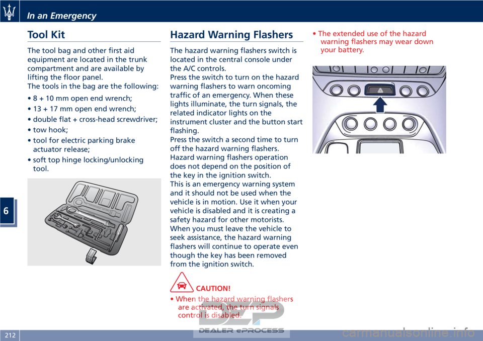
Tool Kit
The tool bag and other first aid
equipment are located in the trunk
compartment and are available by
lifting the floor panel.
The tools in the bag are the following:
•8+10mmopen end wrench;
• 13 + 17 mm open end wrench;
• double flat + cross-head screwdriver;
• tow hook;
• tool for electric parking brakeactuator release;
• soft top hinge locking/unlocking tool.
Hazard Warning Flashers
The hazard warning flashers switch is
located in the central console under
the A/C controls.
Press the switch to turn on the hazard
warning flashers to warn oncoming
traffic of an emergency. When these
lights illuminate, the turn signals, the
related indicator lights on the
instrument cluster and the button start
flashing.
Press the switch a second time to turn
off the hazard warning flashers.
Hazard warning flashers operation
does not depend on the position of
the key in the ignition switch.
This is an emergency warning system
and it should not be used when the
vehicle is in motion. Use it when your
vehicle is disabled and it is creating a
safety hazard for other motorists.
When you must leave the vehicle to
seek assistance, the hazard warning
flashers will continue to operate even
though the key has been removed
from the ignition switch.
CAUTION!
• When the hazard warning flashers are activated, the turn signals
control is disabled. • The extended use of the hazard
warning flashers may wear down
your battery.
In an Emergency
6
212
Page 220 of 296
• If necessary, turn the hazard warningflashers on and place the warning
triangle at the required distance.
WARNING!
• The jack should be used on level firm
ground wherever possible.
• It is recommended that the wheels
of the vehicle be chocked, and that
no person should remain in a vehicle
that is being jacked.
• If the vehicle has been stopped on a
slope or an uneven surface, place
chocks or other suitable items in
front of or behind the wheels to
stop the vehicle from moving.
• Never start or run the engine with
the vehicle on a jack.
• No person should place any portion
of their body under a vehicle that is
supported by a jack.
• Take the bag with compact spare wheel
and tools out of the trunk
compartment and remove it from the
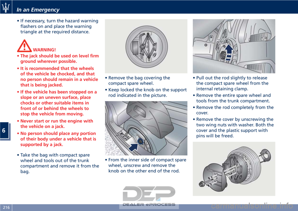
bag. • Remove the bag covering the
compact spare wheel.
• Keep locked the knob on the support rod indicated in the picture.
• From the inner side of compact spare wheel, unscrew and remove the
knob on the other end of the rod. • Pull out the rod slightly to release
the compact spare wheel from the
internal retaining clamp.
• Remove the entire spare wheel and tools from the trunk compartment.
• Remove the rod completely from the cover.
• Remove the cover by unscrewing the two wing nuts with washer. Both the
cover and the plastic support with
pins will be freed.
In an Emergency
6
216
Page 221 of 296

• Remove from the compressor casethe inflation hose and the cable with
a plug for the power outlet.
• Unscrew the valve cap of the compact spare wheel and screw the
fitting of the inflation hose onto the
valve.
• Insert the plug in one of the available power outlets fitted in the
trunk or passenger compartment.
• Turn the key in the ignition switch in MAR (ON) position.
• Turn the compressor on by pressing the switch.
• Stop the compressor pressing switch again, when the pressure indicated
by the gage reaches the
recommended level (see “Tire
Inflation Pressure” in section
“Features and Specifications”) and
screw the cap on the compact spare
wheel valve.
CAUTION!
• In order to obtain a more accurate reading, the compressor should be
switched off when checking the tire
pressure of the compact spare wheel
on the pressure gage.
• Do not run the compressor for more than 20 minutes: there is a risk it
could overheat. Also, prolonged
power absorption may discharge the
battery, subsequently preventing the
engine from starting.
• The compressor has been designed exclusively to inflate compact spare
wheels; do not use it to inflate air
mattresses, dinghies etc.
• Fit the adapter on the wrench. Extend
the wrench as shown, then
loosen by approximately one turn, the five bolts on the wheel to be
changed.
• Open the jack partially, releasing and turning the control lever clockwise.
• Place the jack near the wheel to be changed in one of the indicated
positions.
• Make sure that the head of the jack is correctly inserted in one of the
slots beneath the sole bar.
In an Emergency
6
217
Page 224 of 296
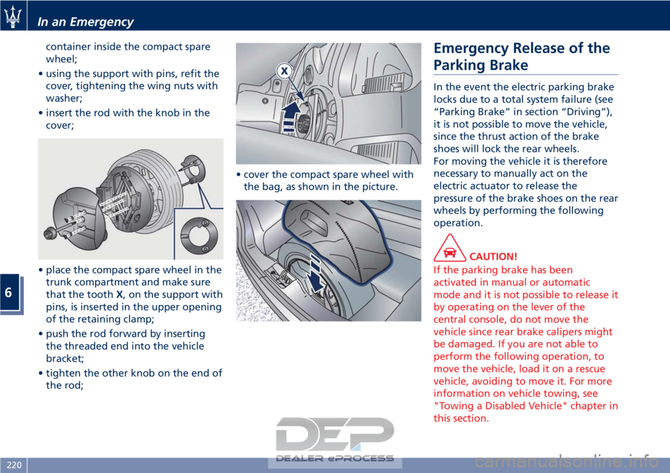
container inside the compact spare
wheel;
• using the support with pins, refit the cover, tightening the wing nuts with
washer;
• insert the rod with the knob in the cover;
• place the compact spare wheel in the trunk compartment and make sure
that the tooth X, on the support with
pins, is inserted in the upper opening
of the retaining clamp;
• push the rod forward by inserting the threaded end into the vehicle
bracket;
• tighten the other knob on the end of the rod; • cover the compact spare wheel with
the bag, as shown in the picture.Emergency Release of the
Parking Brake
In the event the electric parking brake
locks due to a total system failure (see
“Parking Brake” in section “Driving”),
it is not possible to move the vehicle,
since the thrust action of the brake
shoes will lock the rear wheels.
For moving the vehicle it is therefore
necessary to manually act on the
electric actuator to release the
pressure of the brake shoes on the rear
wheels by performing the following
operation.
CAUTION!
If the parking brake has been
activated in manual or automatic
mode and it is not possible to release it
by operating on the lever of the
central console, do not move the
vehicle since rear brake calipers might
be damaged. If you are not able to
perform the following operation, to
move the vehicle, load it on a rescue
vehicle, avoiding to move it. For more
information on vehicle towing, see
"Towing a Disabled Vehicle" chapter in
this section.
In an Emergency
6
220
Page 225 of 296
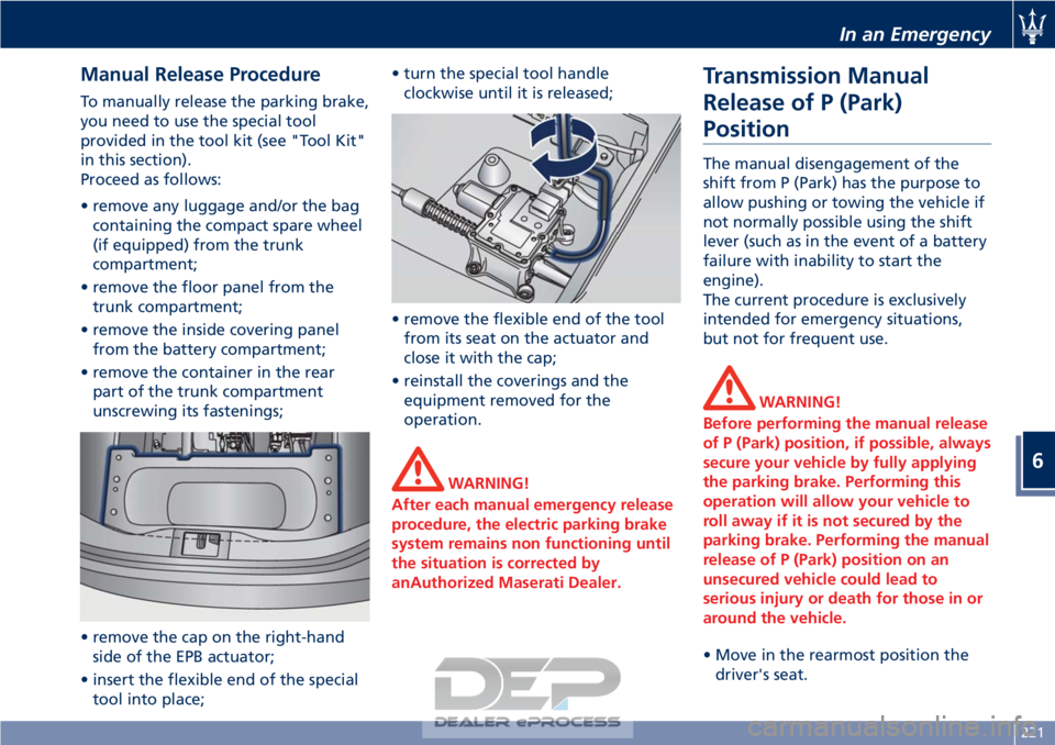
Manual Release Procedure
To manually release the parking brake,
you need to use the special tool
provided in the tool kit (see "Tool Kit"
in this section).
Proceed as follows:
• remove any luggage and/or the bagcontaining the compact spare wheel
(if equipped) from the trunk
compartment;
• remove the floor panel from the trunk compartment;
• remove the inside covering panel from the battery compartment;
• remove the container in the rear part of the trunk compartment
unscrewing its fastenings;
• remove the cap on the right-hand side of the EPB actuator;
• insert the flexible end of the special tool into place; • turn the special tool handle
clockwise until it is released;
• remove the flexible end of the tool from its seat on the actuator and
close it with the cap;
• reinstall the coverings and the equipment removed for the
operation.
WARNING!
After each manual emergency release
procedure, the electric parking brake
system remains non functioning until
the situation is corrected by
anAuthorized Maserati Dealer.
Transmission Manual
Release of P (Park)
Position
The manual disengagement of the
shift from P (Park) has the purpose to
allow pushing or towing the vehicle if
not normally possible using the shift
lever (such as in the event of a battery
failure with inability to start the
engine).
The current procedure is exclusively
intended for emergency situations,
but not for frequent use.
WARNING!
Before performing the manual release
of P (Park) position, if possible, always
secure your vehicle by fully applying
the parking brake. Performing this
operation will allow your vehicle to
roll away if it is not secured by the
parking brake. Performing the manual
release of P (Park) position on an
unsecured vehicle could lead to
serious injury or death for those in or
around the vehicle.
• Move in the rearmost position the driver's
seat.
In an Emergency
6
221
Page 226 of 296
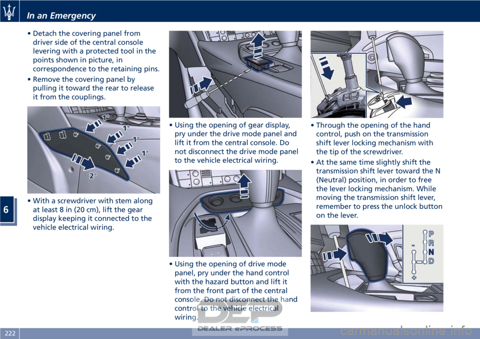
• Detach the covering panel fromdriver side of the central console
levering with a protected tool in the
points shown in picture, in
correspondence to the retaining pins.
• Remove the covering panel by pulling it toward the rear to release
it from the couplings.
• With a screwdriver with stem along at least 8 in (20 cm), lift the gear
display keeping it connected to the
vehicle electrical wiring. • Using the opening of gear display,
pry under the drive mode panel and
lift it from the central console. Do
not disconnect the drive mode panel
to the vehicle electrical wiring.
• Using the opening of drive mode panel, pry under the hand control
with the hazard button and lift it
from the front part of the central
console. Do not disconnect the hand
control to the vehicle electrical
wiring. • Through the opening of the hand
control, push on the transmission
shift lever locking mechanism with
the tip of the screwdriver.
• At the same time slightly shift the transmission shift lever toward the N
(Neutral) position, in order to free
the lever locking mechanism. While
moving the transmission shift lever,
remember to press the unlock button
on the lever.
In an Emergency
6
222
Page 227 of 296
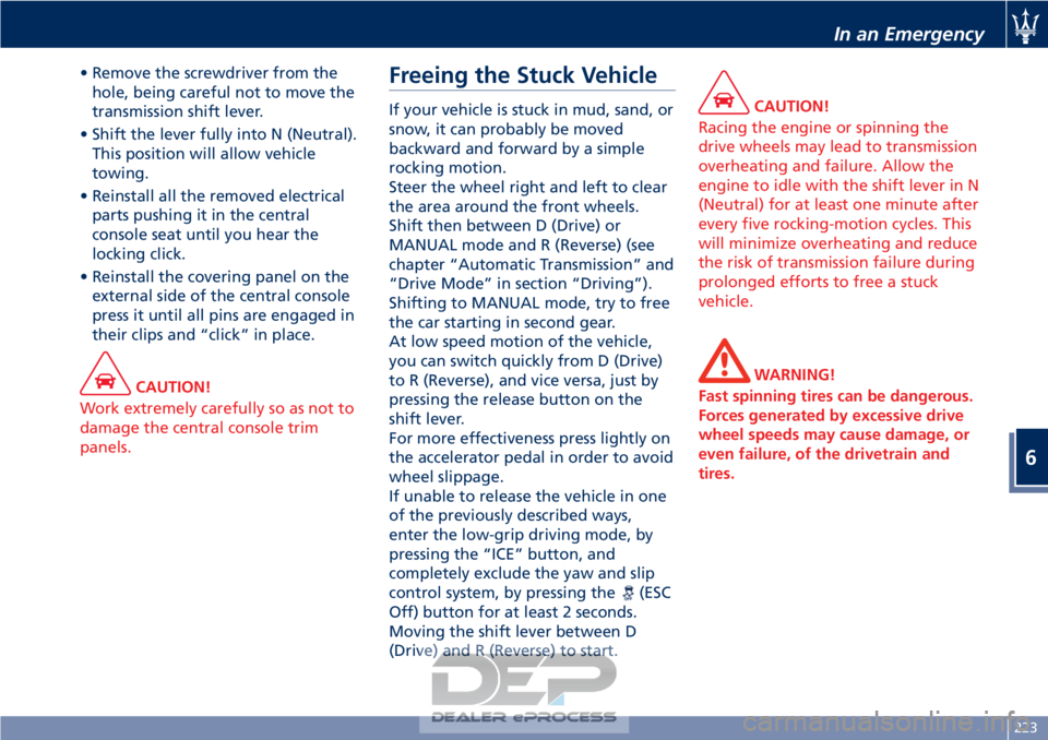
• Remove the screwdriver from thehole, being careful not to move the
transmission shift lever.
• Shift the lever fully into N (Neutral). This position will allow vehicle
towing.
• Reinstall all the removed electrical parts pushing it in the central
console seat until you hear the
locking click.
• Reinstall the covering panel on the external side of the central console
press it until all pins are engaged in
their clips and “click” in place.
CAUTION!
Work extremely carefully so as not to
damage the central console trim
panels.
Freeing the Stuck Vehicle
If your vehicle is stuck in mud, sand, or
snow, it can probably be moved
backward and forward by a simple
rocking motion.
Steer the wheel right and left to clear
the area around the front wheels.
Shift then between D (Drive) or
MANUAL mode and R (Reverse) (see
chapter “Automatic Transmission” and
“Drive Mode” in section “Driving”).
Shifting to MANUAL mode, try to free
the car starting in second gear.
At low speed motion of the vehicle,
you can switch quickly from D (Drive)
to R (Reverse), and vice versa, just by
pressing the release button on the
shift lever.
For more effectiveness press lightly on
the accelerator pedal in order to avoid
wheel slippage.
If unable to release the vehicle in one
of the previously described ways,
enter the low-grip driving mode, by
pressing the “ICE” button, and
completely exclude the yaw and slip
control system, by pressing the
(ESC
Off) button for at least 2 seconds.
Moving the shift lever between D
(Drive) and R (Reverse) to start.
CAUTION!
Racing the engine or spinning the
drive wheels may lead to transmission
overheating and failure. Allow the
engine to idle with the shift lever in N
(Neutral) for at least one minute after
every five rocking-motion cycles. This
will minimize overheating and reduce
the risk of transmission failure during
prolonged efforts to free a stuck
vehicle.
WARNING!
Fast spinning tires can be dangerous.
Forces generated by excessive drive
wheel speeds may cause damage, or
even failure, of the drivetrain and
tires.
In an Emergency
6
223
Page 233 of 296
Use the Vehicle Tow Hook of
the Tool Kit
CAUTION!
The tow hook should only be used for
towing the car on flat roads. Do not
use the tow hook to remove the car
that is stuck on off road stretches.
The tow hook can also be used to tow
the
vehicle on the platform of a tow
truck.
It is necessary to inform the operators
of the rescue vehicle about the vehicle
minimum height to avoid, during its
loading, any contact of the lower ends
of the front or rear bumper with the
tow truck loading ramp.
The tow hook is contained in the tool
kit (see “Tool Kit” in this section) and
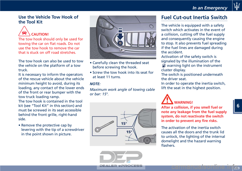
must be screwed in its seat accessible
behind the front grille, right-hand
side.
• Remove the protective cap by levering with the tip of a screwdriver
in the point shown in picture. • Carefully clean the threaded seat
before screwing the hook.
• Screw the tow hook into its seat for at least 11 turns.
NOTE:
Maximum work angle of towing cable
or bar: 15°.
Fuel Cut-out Inertia Switch
The vehicle is equipped with a safety
switch which activates in the event of
a collision, cutting off the fuel supply
and consequently causing the engine
to stop. It also prevents fuel spreading
if the fuel lines are damaged during
the accident.
Activation of the safety switch is
signaled by the illumination of the
warning light on the instrument
cluster display.
The switch is positioned underneath
the driver seat.
In order to operate the inertia switch,
lift the seat in the highest position.
WARNING!
After a collision, if you smell fuel or
note any leakage from the fuel supply
system, do not reactivate the switch
in order to prevent any fire risks.
The activation of the inertia switch
causes
all the doors and the trunk lid
to unlock, the lighting of the internal
domelight and the hazard warning
flashers.
In an Emergency
6
229