2019 MASERATI GRANTURISMO CONVERTIBLE fuel consumption
[x] Cancel search: fuel consumptionPage 123 of 296
Warning and Indicator Lights
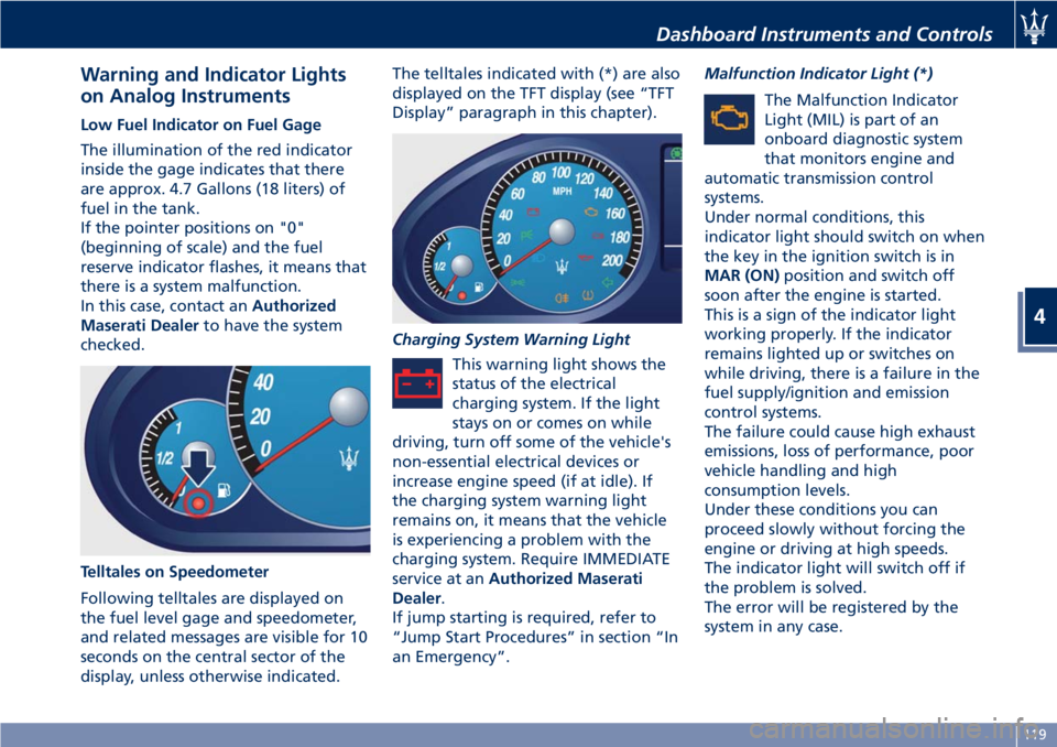
on Analog Instruments Low Fuel Indicator on Fuel Gage
The illumination of the red indicator
inside the gage indicates that there
are approx. 4.7 Gallons (18 liters) of
fuel in the tank.
If the pointer positions on "0"
(beginning of scale) and the fuel
reserve indicator flashes, it means that
there is a system malfunction.
In this case, contact an Authorized
Maserati Dealer to have the system
checked.
Telltales on Speedometer
Following telltales are displayed on
the fuel level gage and speedometer,
and related messages are visible for 10
seconds on the central sector of the
display, unless otherwise indicated. The telltales indicated with (*) are also
displayed on the TFT display (see “TFT
Display” paragraph in this chapter).
Charging System Warning Light
This warning light shows the
status of the electrical
charging system. If the light
stays on or comes on while
driving, turn off some of the vehicle's
non-essential electrical devices or
increase engine speed (if at idle). If
the charging system warning light
remains on, it means that the vehicle
is experiencing a problem with the
charging system. Require IMMEDIATE
service at an Authorized Maserati
Dealer .
If jump starting is required, refer to
“Jump Start Procedures” in section “In
an Emergency”. Malfunction Indicator Light (*)
The Malfunction Indicator
Light (MIL) is part of an
onboard diagnostic system
that monitors engine and
automatic transmission control
systems.
Under normal conditions, this
indicator light should switch on when
the key in the ignition switch is in
MAR (ON) position and switch off
soon after the engine is started.
This is a sign of the indicator light
working properly. If the indicator
remains lighted up or switches on
while driving, there is a failure in the
fuel supply/ignition and emission
control systems.
The failure could cause high exhaust
emissions, loss of performance, poor
vehicle handling and high
consumption levels.
Under these conditions you can
proceed slowly without forcing the
engine or driving at high speeds.
The indicator light will switch off if
the problem is solved.
The error will be registered by the
system in any case.Dashboard Instruments and Controls
4
119
Page 129 of 296
“+“ and “–” Buttons
By means of the “+ “ and “–” buttons,
the user can adjust the instrument
cluster brightness.
When a screen page is viewed, these
buttons can be used to select the
available options (see paragraph "TFT
Display: Screen Pages" in this chapter).
TFT Display: Screen Pages Trip Screen Page
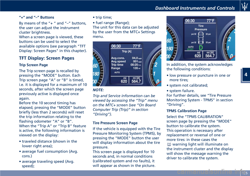
The Trip screen page is recalled by
pressing the “MODE” button. Each
Trip screen page “A” or “B” is timed,
i.e. it is displayed for a maximum of 10
seconds, after which the screen page
previously active is displayed once
again.
Before the 10 second timing has
elapsed, pressing the “MODE” button
briefly (less than 2 seconds) will reset
the trip information relating to the
flashing odometer “A” or “B”.
When the “Trip A” or “Trip B” feature
is active, the following information is
viewed on the display:
• traveled distance (shown in the
lower right area);
• average fuel consumption (Avg.
cons.)
• average traveling speed (Avg.
speed); • trip time;
• fuel range (Range);
The unit for this data can be adjusted
by the user from the MTC+ Settings
menu.
NOTE:
Trip and Service information can be
viewed by accessing the “Trip” menu
on the MTC+ screen (see “On Board
Computer Trip (Trip)” in section
“Driving”).
Tire Pressure Screen Page
If the vehicle is equipped with the Tire
Pressure Monitoring System (TPMS), by
pressing the "MODE" button the user
will display information about the tire
pressure.
This screen page is displayed for 10
seconds and, in normal conditions
(calibrated system and no faults), it
will appear as shown in the picture. In addition, the system acknowledges
the following conditions:
• low pressure or puncture in one or
more tires;
• system not calibrated;
• system failure.
For further details, see “Tire Pressure
Monitoring System - TPMS” in section
“Driving”.
TPMS Calibration Page
Select the “TPMS CALIBRATION"
screen page by pressing the "MODE"
button to calibrate the system.
This operation is necessary after
replacement or reversal of one or
more tires: in these cases the
warning light will illuminate on
the instrument cluster and the display
will show the message warning the
driver to calibrate the system.Dashboard Instruments and Controls
4
125
Page 134 of 296
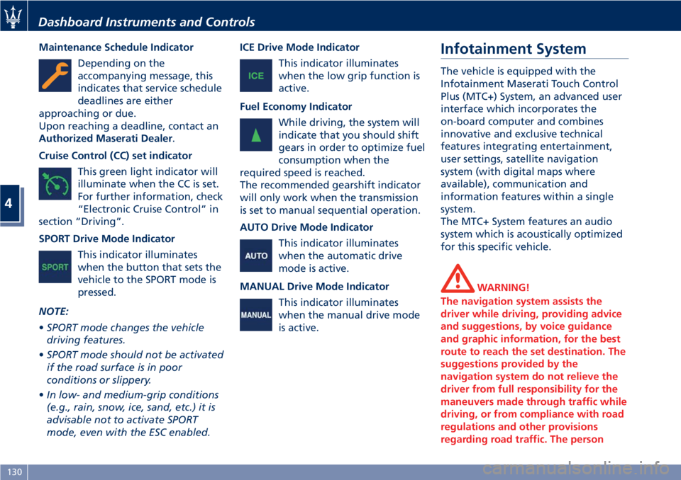
Maintenance Schedule Indicator
Depending on the
accompanying message, this
indicates that service schedule
deadlines are either
approaching or due.
Upon reaching a deadline, contact an
Authorized Maserati Dealer .
Cruise Control (CC) set indicator
This green light indicator will
illuminate when the CC is set.
For further information, check
“Electronic Cruise Control” in
section “Driving”.
SPORT Drive Mode Indicator
This indicator illuminates
when the button that sets the
vehicle to the SPORT mode is
pressed.
NOTE:
• SPORT mode changes the vehicle
driving features.
• SPORT mode should not be activated
if the road surface is in poor
conditions or slippery.
• In low- and medium-grip conditions
(e.g., rain, snow, ice, sand, etc.) it is
advisable not to activate SPORT
mode, even with the ESC enabled. ICE Drive Mode Indicator
This indicator illuminates
when the low grip function is
active.
Fuel Economy Indicator
While driving, the system will
indicate that you should shift
gears in order to optimize fuel
consumption when the
required speed is reached.
The recommended gearshift indicator
will only work when the transmission
is set to manual sequential operation.
AUTO Drive Mode Indicator
This indicator illuminates
when the automatic drive
mode is active.
MANUAL Drive Mode Indicator
This indicator illuminates
when the manual drive mode
is active. Infotainment System The vehicle is equipped with the
Infotainment Maserati Touch Control
Plus (MTC+) System, an advanced user
interface which incorporates the
on-board computer and combines
innovative and exclusive technical
features integrating entertainment,
user settings, satellite navigation
system (with digital maps where
available), communication and
information features within a single
system.
The MTC+ System features an audio
system which is acoustically optimized
for this specific vehicle.
WARNING!
The navigation system assists the
driver while driving, providing advice
and suggestions, by voice guidance
and graphic information, for the best
route to reach the set destination. The
suggestions provided by the
navigation system do not relieve the
driver from full responsibility for the
maneuvers made through traffic while
driving, or from compliance with road
regulations and other provisions
regarding road traffic. The personDashboard Instruments and Controls
4
130
Page 162 of 296
Normal Starting of the
Engine
WARNING!
It is dangerous to run the engine in an
enclosed area. The engine consumes
oxygen and discharges carbon
dioxide, carbon monoxide and other
toxic gases in the atmosphere.
WARNING!
California Proposition 65
Operating, servicing and maintaining
a passenger vehicle or off-road vehicle
can expose you to chemicals including
such as, engine exhaust, carbon
monoxide, phthalates and lead, that
which are know to the State of
California to cause cancer and birth
defects or other reproductive harm. To
minimize exposure, avoid breathing
exhaust, do not idle the engine except
as necessary, service your vehicle in a
well-ventilated area and wear gloves
or wash your hands frequently when
servicing your vehicle. For more
information go to: www.P65Warnings.ca.gov/passenger-
vehicle
When you open a door to get into the
car
, the instrument cluster turns on.
The TFT displays the complete
odometer, time, outside temperature
and the
open doors indicator.
Before starting the engine, close the
doors, adjust your seat, the inside and
outside mirrors, fasten your seat belt
and instruct all other occupants to
buckle their seat belts.
Make sure that the Electric Parking
Brake (EPB) is applied.
The shift lever must be in P (Park) or N
(Neutral) position before you can start
the engine. Apply the brakes before
shifting into any driving gear (see
“Automatic Transmission” in this
section).
CAUTION!
• Before starting the engine, switch off the electrical devices with a high
power consumption (air-conditioning
and heating system, heated rear
window, headlights, etc.).
• Do not start the engine if the fuel level in the tank is low. Press the brake pedal and turn the key
in
the ignition switch to MAR (ON)
position.
Instrument cluster displays the initial
sequence with warning light and
analog instruments test routine.
Turn the key into AVVposition and
release it when the engine starts. The
key will return to MAR (ON)position
automatically.
Do not hold the key in AVVposition
for a long time.
If the engine fails to start, the starter
will disengage automatically after 10
seconds. If you wish to stop the
cranking of the engine prior to
starting it, turn the key to STOP (OFF)
position.
If the engine does not start, turn the
key to STOP (OFF) position and wait
for the gear display to go off. Then
repeat the entire procedure.
NOTE:
Normal starting of either a cold or a
warm engine is obtained without
pumping or pressing the accelerator
pedal.
Driving
5
158
Page 163 of 296
Engine Start Failure
CAUTION!
• Do not attempt to push or tow your vehicle to get it started. Vehicles
equipped with an automatic
transmission cannot be started this
way.
• If the vehicle battery is dead, booster cables may be used to obtain a start
from a booster battery or the
battery in another vehicle. This type
of start can be dangerous if done
improperly. See “Auxiliary Jump
Start Procedure” in section “In an
Emergency” for further information.
Starting by cold engine
Start-of
f slowly, avoiding sudden
acceleration and rev the engine up at
low medium speeds. High-
performance driving should be
avoided until the engine temperature
reaches 149-158°F (65-70°C).
Engine Turn-Off
• Place the shift lever in P (Park) (see “Automatic Transmission” in this
section).
• With the engine at idle, turn the key in the ignition switch to STOP (OFF)position. A burst on the accelerator
pedal before turning off the engine
has no purpose and increases fuel
consumption.
WARNING!
Never leave a vehicle out of the P
(Park) position, as it could move.
The key can only be removed from the
ignition
switch when the transmission
is in P (Park) position and within 30
seconds after turning the key to STOP
(OFF) position. If you do not remove
the key within 30 seconds, you will
need to turn it back to MAR (ON)and
then to STOP (OFF) position to have a
further 30 seconds within which to
remove the key from the ignition
switch.
In the event that the key unlocking
system fails or if it is not possible to
shift the transmission to P (Park)
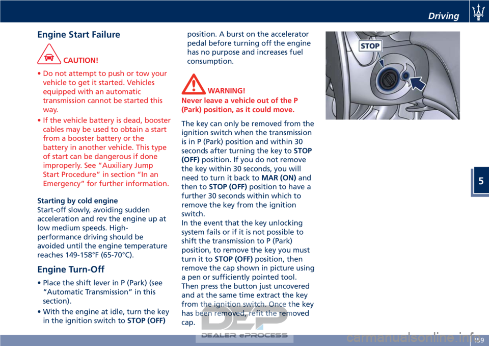
position, to remove the key you must
turn it to STOP (OFF) position, then
remove the cap shown in picture using
a pen or sufficiently pointed tool.
Then press the button just uncovered
and at the same time extract the key
from the ignition switch. Once the key
has been removed, refit the removed
cap.
Driving
5
159
Page 172 of 296
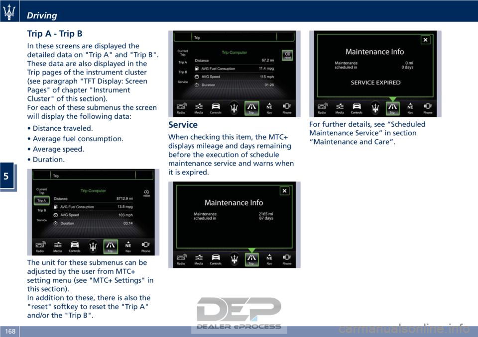
TripA-TripB
In these screens are displayed the
detailed data on "Trip A" and "Trip B".
These data are also displayed in the
Trip pages of the instrument cluster
(see paragraph "TFT Display: Screen
Pages" of chapter "Instrument
Cluster" of this section).
For each of these submenus the screen
will display the following data:
• Distance traveled.
• Average fuel consumption.
• Average speed.
• Duration.
The unit for these submenus can be
adjusted by the user from MTC+
setting menu (see "MTC+ Settings" in
this section).
In addition to these, there is also the
"reset" softkey to reset the "Trip A"
and/or the "Trip B".
Service
When checking this item, the MTC+
displays mileage and days remaining
before the execution of schedule
maintenance service and warns when
it is expired.For further details, see “Scheduled
Maintenance Service” in section
“Maintenance and Care”.
Driving
5
168
Page 177 of 296
When the system refuses to engage a
gear, an acoustic signal will sound for
a few seconds.
Sequential manual operation can only
be selected from the D (Drive) position
whatever the function (SPORT,
NORMAL) active at the time of the
request. The gear selected by the
automatic transmission will remain
engaged when the transmission shift
lever is moved.
Shifting the lever back to D (Drive),
automatic operation will instantly be
resumed, and a gear will be engaged
based on the driving style and mode
selected.
In the event of a failure of the
sequential manual gearshift system,
the transmission ECU will select
automatic operation.
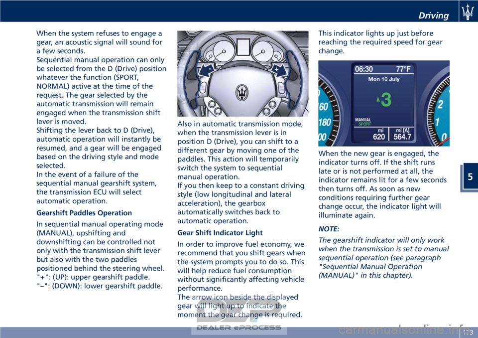
Gearshift Paddles Operation
In sequential manual operating mode
(MANUAL), upshifting and
downshifting can be controlled not
only with the transmission shift lever
but also with the two paddles
positioned behind the steering wheel.
"+": (UP): upper gearshift paddle.
"–": (DOWN): lower gearshift paddle.Also in automatic transmission mode,
when the transmission lever is in
position D (Drive), you can shift to a
different gear by moving one of the
paddles. This action will temporarily
switch the system to sequential
manual operation.
If you then keep to a constant driving
style (low longitudinal and lateral
acceleration), the gearbox
automatically switches back to
automatic operation.
Gear Shift Indicator Light
In order to improve fuel economy, we
recommend that you shift gears when
the system prompts you to do so. This
will help reduce fuel consumption
without significantly affecting vehicle
performance.
The arrow icon beside the displayed
gear will light up to indicate the
moment the gear change is required.This indicator lights up just before
reaching the required speed for gear
change.
When the new gear is engaged, the
indicator turns off. If the shift runs
late or is not performed at all, the
indicator remains lit for a few seconds
then turns off. As soon as new
conditions requiring further gear
change occur, the indicator light will
illuminate again.
NOTE:
The gearshift indicator will only work
when the transmission is set to manual
sequential operation (see paragraph
"Sequential Manual Operation
(MANUAL)" in this chapter).
Driving
5
173
Page 195 of 296

WARNING!
• Improperly inflated tires can be
dangerous.
• Under-inflation increases tire flexing
and can result in tire overheating.
• Over-inflation reduces a tire's ability
to cushion shock. Objects on the
road and potholes can cause
damage that results in tire failure.
• Over-inflated or under-inflated tires
can affect vehicle handling and can
fail suddenly, resulting in loss of
vehicle control.
• Unequal tire pressures can cause
steering problems.
• Unequal tire pressures from one side
of the vehicle to the other can cause
the vehicle to drift to the right or
left.
• Always drive with each tire inflated
to the recommended cold tire
inflation pressure.
Economy
Improper
inflation pressures may
cause uneven wear patterns to
develop across the tire tread. These
abnormal wear patterns will reduce
tread life resulting in a need for
earlier tire replacement. Under- inflation also increases tire rolling
resistance resulting in higher fuel
consumption.
Ride comfort and vehicle stability
Proper tire inflation contributes to a
comfortable ride. Over-inflation
produces a jarring and uncomfortable
ride.
Tire Pressure Checkup
The proper cold tire inflation pressure
is indicated on the driver's side rear
door pillar and on the table “Tire
Inflation Pressure” in section
“Features and Specifications”.
Inflation pressure specified on the
table always refers to “cold tire
inflation pressure”. Cold tire inflation
pressure is defined as the tire pressure
after the vehicle has not been driven
for at least three hours, or driven less
than 1 mi (1,6 km) after a three hour
period.
Check tire pressures more often in
case of significant outside
temperature changes, as tire pressure
varies according to temperature
changes.
The pressure should be checked and if
necessary adjusted; tire wear and
overall conditions should also be
checked monthly. Tire pressures
change by approximately 1 PSI (0,07
bar) per 12°F (7°C) of air temperature
change. Keep this in mind when
checking tire pressure inside a garage,
especially in winter.
Example: If garage temperature = 68°F
(20°C) and the outside temperature =
32°F (0°C) then the cold tire inflation
pressure should be increased by 3 PSI
(0,21 bar) for every 12°F (7°C) for this
outside temperature condition.
Tire pressure may increase from 2 to 6
PSI (0,13 to 0,4 bar) during operation.
DO NOT reduce this normal pressure
build-up or your tire pressure will be
too low. After inspecting or adjusting
the tire pressure, always reinstall the
valve stem cap. This will prevent
moisture and dirt from entering the
valve stem, which could damage the
valve stem and the TPMS sensor
connected to it.
Tread Wear Indicators
Tread wear indicators are in the
original equipment tires to help you
determine when your tires should be
replaced.
These indicators are molded into the
bottom of the tread grooves.
When the tread is worn to one of the
tread wear indicators, the tire should
be replaced.
Driving
5
191