2019 MASERATI GRANTURISMO CONVERTIBLE lock
[x] Cancel search: lockPage 242 of 296

you should perform the following
inspections more frequently than
recommended on the “Scheduled
Service Plan”:
• check front disc brake pad conditionsand wear;
• check cleanliness of hood and trunk locks, cleanliness and lubrication of
linkage;
• visually inspect conditions of: engine, transmission, pipes and hoses
(exhaust - fuel system - brakes) and
rubber elements (trunks - sleeves -
bushes - etc.);
• check battery charge;
• visually inspect condition of the accessory drive belts;
• check and, if necessary, change engine oil and replace oil filter;
• check and, if necessary, replace pollen filter of the A/C system;
• check and, if necessary, replace air cleaner filter.
CAUTION!
All maintenance operations for the
vehicle must be carried out by the
Authorized Maserati Dealer . For
routine and minor maintenance
operations which you can carry out yourself, make sure that you have the
necessary experience and always use
suitable equipment, original
Maserati
spare parts (or equivalent) and the
prescribed fluids. Shall this not be the
case, do not carry any operation on
your own and contact an Authorized
Maserati Dealer.
Onboard Diagnostic System
Your vehicle is equipped with a
sophisticated onboard diagnostic
system. This system monitors the
performance of the emissions, engine,
and automatic transmission control
systems. When these systems are
operating properly, your vehicle will
provide excellent performance and
fuel economy, as well as engine
emissions suited to current
government regulations.
If any of these systems require service,
the system will turn on the
Malfunction Indicator Light on the
instrument cluster display (refer to
“Instrument Cluster” in section
“Dashboard Instruments and
Controls”). The system stores as well
diagnostic codes and other
information to assist your service
technician by performing repairs. Although the vehicle will be driveable
and will not need towing, contact an
Authorized Maserati Dealer
for service
as soon as possible.
CAUTION!
• Prolonged driving with the
MIL
on could cause further damage to
the emissions control system. It could
also affect fuel economy and
drivability. The vehicle must be
serviced before any emissions tests
can be performed.
•Ifthe
MIL is flashing while the
engine is running, severe catalytic
converter damage and power loss
will soon occur. Immediate service at
the Authorized Maserati Dealer is
required.
Spare Parts
Use of genuine parts for normal or
scheduled maintenance and repairs is
highly recommended to ensure
excellent performance.
Damage or failures caused by
non-genuine spare parts used for
maintenance and repairs will not be
covered by the manufacturer's
warranty.
Maintenance and Care
7
238
Page 250 of 296

Always use washer fluid when using
the wipers to remove salt or dirt from
a dry windshield.
Avoid using the wiper blades to
remove frost or ice from the
windshield. Keep the blade rubber out
of contact with petroleum products
such as engine oil, gasoline, etc.
Spray nozzles
If the jet does not work, first check
that there is fluid in the pan (see
paragraph “Level checks” in this
section) then check that the nozzles
are not clogged.
Blades Replacement
• Move the right multifunction leverinto “OFF” position, (see chapter
“Windshield Wipers and Washers” in
section “Understanding the
Vehicle”).
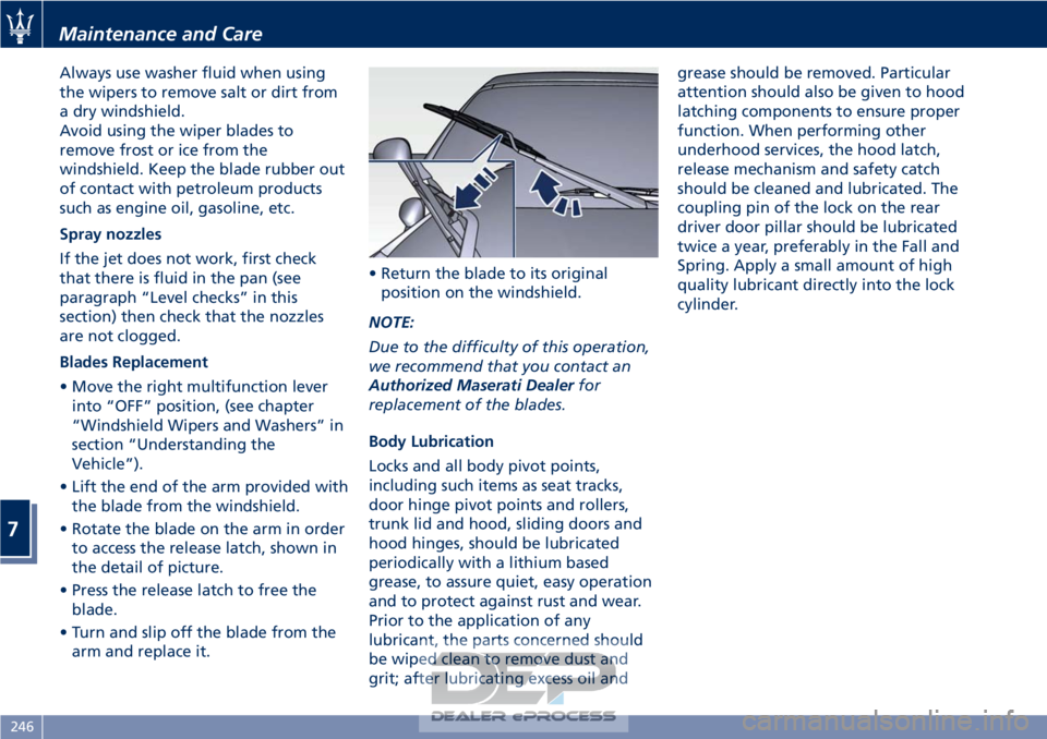
• Lift the end of the arm provided with the blade from the windshield.
• Rotate the blade on the arm in order to access the release latch, shown in
the detail of picture.
• Press the release latch to free the blade.
• Turn and slip off the blade from the arm and replace it. • Return the blade to its original
position on the windshield.
NOTE:
Due to the difficulty of this operation,
we recommend that you contact an
Authorized Maserati Dealer for
replacement of the blades.
Body Lubrication
Locks and all body pivot points,
including such items as seat tracks,
door hinge pivot points and rollers,
trunk lid and hood, sliding doors and
hood hinges, should be lubricated
periodically with a lithium based
grease, to assure quiet, easy operation
and to protect against rust and wear.
Prior to the application of any
lubricant, the parts concerned should
be wiped clean to remove dust and
grit; after lubricating excess oil and grease should be removed. Particular
attention should also be given to hood
latching components to ensure proper
function. When performing other
underhood services, the hood latch,
release mechanism and safety catch
should be cleaned and lubricated. The
coupling pin of the lock on the rear
driver door pillar should be lubricated
twice a year, preferably in the Fall and
Spring. Apply a small amount of high
quality lubricant directly into the lock
cylinder.
Maintenance and Care
7
246
Page 252 of 296

(Continued)
quick coupling from the negative
pole (–) of the battery.
If the battery needs to be removed
from
its compartment, you must first
detach the terminal clamp from
negative pole (–) and then the other
terminal clamp from positive pole (+),
after removing the protective cover.
Battery poles are marked positive (+)
and negative (–) and are identified on
the battery case.
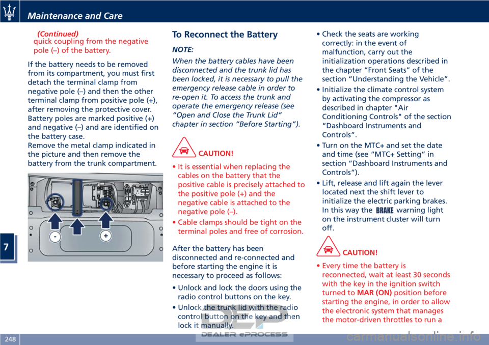
Remove the metal clamp indicated in
the picture and then remove the
battery from the trunk compartment.
To Reconnect the Battery
NOTE:
When the battery cables have been
disconnected and the trunk lid has
been locked, it is necessary to pull the
emergency release cable in order to
re-open it. To access the trunk and
operate the emergency release (see
“Open and Close the Trunk Lid”
chapter in section “Before Starting”).
CAUTION!
• It is essential when replacing the cables on the battery that the
positive cable is precisely attached to
the positive pole (+) and the
negative cable is attached to the
negative pole (–).
• Cable clamps should be tight on the terminal poles and free of corrosion.
After the battery has been
disconnected
and re-connected and
before starting the engine it is
necessary to proceed as follows:
• Unlock and lock the doors using the radio control buttons on the key.
• Unlock the trunk lid with the radio control button on the key and then
lock it manually. • Check the seats are working
correctly: in the event of
malfunction, carry out the
initialization operations described in
the chapter “Front Seats” of the
section “Understanding the Vehicle”.
• Initialize the climate control system by activating the compressor as
described in chapter "Air
Conditioning Controls" of the section
“Dashboard Instruments and
Controls”.
• Turn on the MTC+ and set the date and time (see “MTC+ Setting” in
section “Dashboard Instruments and
Controls”).
• Lift, release and lift again the lever located next the shift lever to
initialize the electric parking brakes.
In this way the
warning light
on the instrument cluster will turn
off.
CAUTION!
• Every time the battery is reconnected, wait at least 30 seconds
with the key in the ignition switch
turned to MAR (ON) position before
starting the engine, in order to allow
the electronic system that manages
the motor-driven throttles to run a
Maintenance and Care
7
248
Page 257 of 296

Pos.Amp. –
Color System /
Component
F04 Maxi 40 A –
Orange ABS cylinder
F05 Maxi 40 A –
Orange A.C. Node
F06 Maxi 60 A –
Blue Fan 2 relay
F07 30A–
Green T07 I.E. main
relay
F08 7.5A–
Brown T08 - Air
conditioner
compressor
relay
F09 7.5A–
Brown T05 stop light
control relay
F10 15 A – Blue T06 horn relay
F11 10 A – Red LH high-beam
F14 7.5A–
Brown Third stop
F15 15 A – Blue Alternator
sensing
F16 10 A – Red LH spot light
F17 10 A – Red RH high-beam
F18 7.5A–
Brown I.E. bank
F19 7.5 A – Blue T02 DRL lights
relayPos.Amp. –
Color System /
Component
F20 10 A – Red T17 Key lock
solenoid relay
F21 - Not used
F22 - Not used
F23 10 A – Red ABS Electronics
F24 10 A – Red RH spot light
F30 30A–
Green T20 ignition
relay
F81 Maxi 50 A –
Red CPL2
F82 - Not used
F83 Maxi 50 A –
Red Air pump relay
F84 20A–
Yellow Ignition switch.
F85 30A–
Green Headlight
washers
F87 - Not used
F88 15 A – Blue Main
injector/coil
relay - cylinders
1-4
F89 15 A – Blue Main
injector/coil
relay - cylinders
5-8Pos.
Amp. –
Color System /
Component
F90 15 A – Blue Main I.E. relay,
secondary
connected
devices
F91 10 A – Red Main relay, I.E.
ECU
F92 15 A – Blue Main relay,
oxygen sensors
F93 - Not used
F94 7.5A–
Brown NCS
F95 7.5A–
Brown CSG
F96 7.5A–
Brown Alternator
F97 10 A – Red I.E. ECU
F98 - Not used
F99 - Not used
F100 - Not used
F101 - Not used
F102 - Not used
F103 - Not used
F104 - Not used
F105 - Not used
F106 - Not used
Maintenance and Care
7
253
Page 258 of 296

Pos.Amp. –
Color System /
Component
F107 - Not used
Fuses in Passenger
Compartment
• To access the fuses lift the guard on
the left side of the steering wheel.
The fuses are housed in two control
boxes. The following table points out the
position as featured in the picture, the
type and function of the fuses
included in these control boxes.
Passenger Compartment Fuses
Pos. Amp. –
Color System / Component
F12 15 A – Blue Right-hand low
beam
F13 15 A – Blue Left-hand low beam
F31 7.5 A – Brown A/C unit, NBC (Body
Computer Node),
high beam relay
F32 10 A – Red Domelights, step
lights, CAV, driver-
and passenger-side
footwell lights,
outside mirror lights
F33 30 A – Green Driver’s seat
(movement)
F34 30 A – Green Passenger’s seat
(movement)
F35 7.5 A – Brown ACC, FN and LF relay
coil
F36 10 A – Red NQS
F37 10 A – Red NQS (Instrument
Cluster Node), CPP,
CPD
F38 15 A – Blue Rear lid lock
Maintenance and Care
7
254
Page 259 of 296

Pos. Amp. –Color System / Component
F39 15 A – Blue NIM (Inside Roof
Node), NCL (Air
conditioning and
heating system
node), OBD socket,
CSA (Alarm system
siren ECU), CAV
(Motion sensing
alarm ECU), radio,
NAVTRAK
F40 30 A – Green Heated rear window
F41 - Not used
F42 7.5 A – Brown NCL and windshield
wiper control
F43 30 A – Green Windshield
wiper/washer
(Connected Devices
Relay INT/A)
F44 20 A – Yellow Front and rear power
outlets (INT/A device
relay) front seat
heating (passenger
side)
F45 - Not used
F46 20 A – Yellow NPG/NPP locksPos. Amp. –
Color System / Component
F47 30 A – Green NPG (Driver’s door
node)
F48 30 A – Green NPP (Passenger’s
door node)
F49 7.5 A – Brown NVO (Steering wheel
node), CSG (Power
steering ECU), CSP
(Twilight/rain sensor
ECU), NIM (Inside
Roof Node), NCL,
Radio, CEM, CRP,
domelight molding,
NAVTRAK
F50 7.5 A – Brown Air bag system
F51 7.5 A – Brown NCA (Automatic
Gearbox Node)
F52 15 A – Blue Front seat heating
(driver side) (INT/A
device relay)
F53 10 A – Red Rear fog lights
Fuses in Trunk Compartment
• To access the fuses, remove the floor
panel. • Remove the inside covering panel of
the battery compartment.
There are two control boxes.
• To access the fuses inside the control boxes, remove the covers by levering
up the fastening tabs.
Maintenance and Care
7
255
Page 262 of 296

Reverse and Rear Fog Light
To replace a bulb of these lights:
• Lift the trunk compartment lid.
• Remove the panel from the trunk lid.
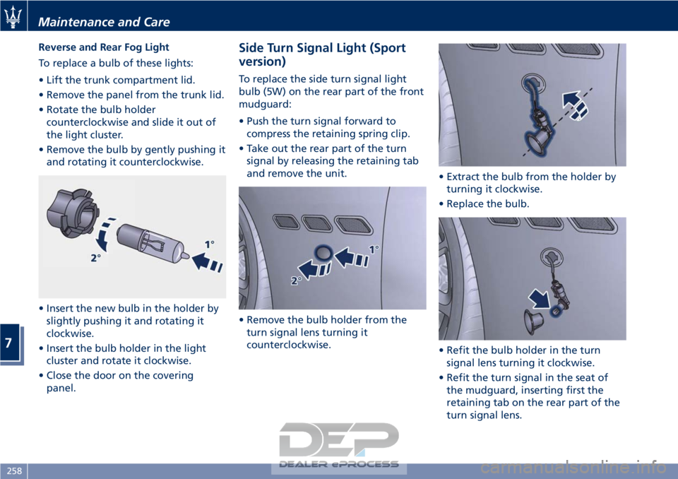
• Rotate the bulb holdercounterclockwise and slide it out of
the light cluster.
• Remove the bulb by gently pushing it and rotating it counterclockwise.
• Insert the new bulb in the holder by slightly pushing it and rotating it
clockwise.
• Insert the bulb holder in the light cluster and rotate it clockwise.
• Close the door on the covering panel.Side Turn Signal Light (Sport
version)
To replace the side turn signal light
bulb (5W) on the rear part of the front
mudguard:
• Push the turn signal forward tocompress the retaining spring clip.
• Take out the rear part of the turn signal by releasing the retaining tab
and remove the unit.
• Remove the bulb holder from the turn signal lens turning it
counterclockwise. • Extract the bulb from the holder by
turning it clockwise.
• Replace the bulb.
• Refit the bulb holder in the turn signal lens turning it clockwise.
• Refit the turn signal in the seat of the mudguard, inserting first the
retaining tab on the rear part of the
turn signal lens.
Maintenance and Care
7
258
Page 263 of 296

• Press the front part of the turnsignal lens until hearing the spring
clip click into position.
CAUTION!
Proceed with care when removing the
side turn signal light to avoid
damaging to the vehicle body or the
turn signal itself.
Side Turn Signal Lights (MC
version)
To replace side turn signal light bulb
(5W) on the rear part of the front
mudguard:
• Gently pry the turn signal light off the vehicle body by levering with a
non-metal tool under the rubber
part.
CAUTION!
Proceed with care when removing side
turn signal light to avoid damaging
the vehicle body or to the turn signal
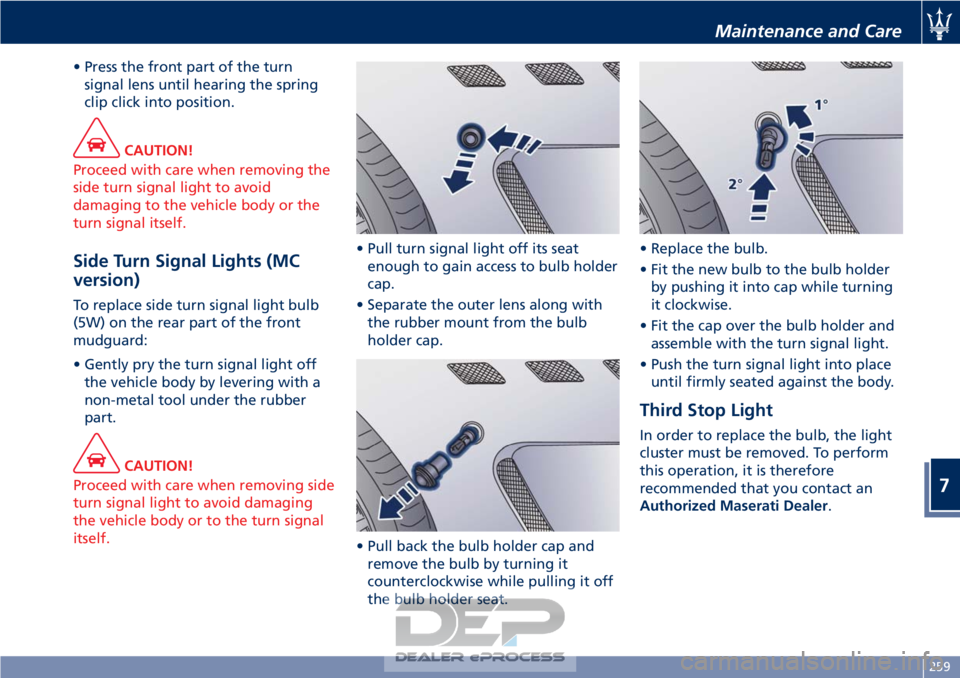
itself. • Pull turn signal light off its seat
enough
to gain access to bulb holder
cap.
• Separate the outer lens along with the rubber mount from the bulb
holder cap.
• Pull back the bulb holder cap and remove the bulb by turning it
counterclockwise while pulling it off
the bulb holder seat. • Replace the bulb.
• Fit the new bulb to the bulb holder
by pushing it into cap while turning
it clockwise.
• Fit the cap over the bulb holder and assemble with the turn signal light.
• Push the turn signal light into place until firmly seated against the body.
Third Stop Light
In order to replace the bulb, the light
cluster must be removed. To perform
this operation, it is therefore
recommended that you contact an
Authorized Maserati Dealer.
Maintenance and Care
7
259