2019 MASERATI GRANTURISMO CONVERTIBLE ignition
[x] Cancel search: ignitionPage 190 of 296
the speed stored. Every time rotating
section is reset, the speed is increased
or decrease by approx. 0.6 mph (1
Km/h). Keep the rotating section
turned to vary the speed
continuously. When a new speed is
reached, it will automatically remain
constant.
• Button "RCL" at end of left multifunction lever is used to resume
the speed stored.
NOTE:
• When the key in the ignition switch
is turned to STOP (OFF)position or
ON/OFF switch is in the "OFF"
position, the speed stored is erased
and the system deactivated.
• The CC must be deactivated when
not in use.
WARNING!
Leaving the Cruise Control system on
when not in use is dangerous. You
could accidentally set the system or
cause it to go faster than you want.
Always leave the CC off when you are
not using it. Storing a Speed
T
urn the ON/OFF switch to "ON" and
reach the desired speed driving
normally. Turn the rotating section in
the middle of the left multifunction
lever to "+" for at least 3 seconds and
then release it.
The vehicle speed is stored and the
accelerator pedal can be released.
The vehicle will proceed at the
constant speed stored until the brake
pedal is pressed.
If necessary, (for example, to pass
another vehicle), you can accelerate by
simply pressing the accelerator pedal.
Afterward, when you release the
accelerator pedal, the vehicle will
return to the speed previously stored.
Resuming the Speed Stored
If the CC has been deactivated after
braking, the speed previously stored
can be resumed as follows:
• gradually accelerate until you reach a speed close to that stored;
• engage the gear selected when the speed was stored (4th, 5th or 6th
gear);
• press button "RCL".
Increasing the Speed Stored
The speed stored can be increased in
two ways: • by pressing the accelerator and then
storing the new speed reached (turn
the rotating section in the middle of
the left multifunction lever for more
than 3 seconds); or
• by turning the rotating section to position "+": each impulse
transmitted by the rotating section
will cause a slight increase in speed
(about 0.6 mph/1 Km/h), whereas a
constant pressure on the same
rotating section will cause a
continuous increase in speed. When
the rotating section is released, the
new speed will be automatically
stored in the memory.
Decreasing the Speed Stored
The speed stored can be reduced in
two ways:
• by deactivating the CC, pressing the brake pedal and then storing the
new speed (turning the rotating
section to position “+” for at least 3
seconds); or
• by keeping the rotating section turned to position “-” until reaching
the new speed, which will be stored
automatically.
Resetting the Speed Stored
The speed stored is automatically
reset:
Driving
5
186
Page 201 of 296
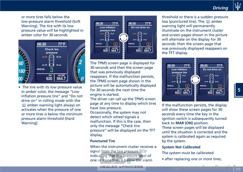
or more tires falls below the
low-pressure alarm threshold (Soft
Warning). The tire with its low
pressure value will be highlighted in
amber color for 30 seconds.
• The tire with its low pressure value in amber color, the message “Low
inflation pressure tire” and "Do not
drive on" in rolling mode with the
amber warning light always on
activates when the pressure of one
or more tires is below the minimum
pressure alarm threshold (Hard
Warning). The TPMS screen page is displayed for
30 seconds and then the screen page
that was previously displayed
reappears. If the malfunction persists,
the TPMS screen page shown in the
picture will be automatically displayed
for 30 seconds the next time the
engine is started.
The driver can call up the TPMS screen
page at any time to display which tires
have low pressure.
Occasionally, the system may not
detect which wheel signals a
malfunction. If this is the case, then
only the message “Check tire
pressure” will be displayed on the TFT
display.
Punctured Tire
When the instrument cluster receives a
signal from the tire pressure ECU
indicating that the pressure level of
one or more tires is below the alarm threshold or there is a sudden pressure
loss (punctured tire). The
amber
warning light will permanently
illuminate on the instrument cluster
and screen pages shown in the picture
will alternate on the display for 30
seconds: then the screen page that
was previously displayed reappears on
the TFT display.
If the malfunction persists, the display
will show these screen pages for 30
seconds every time the key in the
ignition switch is subsequently turned
back to MAR (ON) position.
These screen pages will be displayed
until the situation is corrected and the
system is calibrated again as required
by the system.
System Not Calibrated
The system must be calibrated:
• after replacing one or more tires;
Driving
5
197
Page 206 of 296
Refueling
Fuel Filler Neck Access
The fuel filler door is found on the
rear, left-hand side of the vehicle.
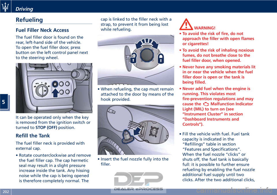
To open the fuel filler door, press
button on the left control panel next
to the steering wheel.
It can be operated only when the key
is removed from the ignition switch or
turned toSTOP (OFF) position.
Refill the Tank
The fuel filler neck is provided with
external cap.
• Rotate counterclockwise and remove
the fuel filler cap. The cap hermetic
seal may result in a slight pressure
increase inside the tank. Any hissing
noise while the cap is being opened
is therefore completely normal. The cap is linked to the filler neck with a
strap, to prevent it from being lost
while refueling.
• When refueling, the cap must remain attached to the door by means of the
hook provided.
• Insert the fuel nozzle fully into the filler.
WARNING!
• To avoid the risk of fire, do not
approach the filler with open flames
or cigarettes!
• To avoid the risk of inhaling noxious
fumes, do not breathe close to the
fuel filler door, when opened.
• Never have any smoking materials lit
in or near the vehicle when the fuel
filler door is open or the tank is
being filled.
• Never add fuel when the engine is
running. This violates most
fire-prevention regulations and may
cause the
Malfunction Indicator
Light (MIL) to turn on (see
“Instrument Cluster” in section
“Dashboard Instruments and
Controls”).
• Fill the vehicle with fuel. Fuel tank capacity
is indicated in the
“Refillings” table in section
“Features and Specifications”.
When the fuel nozzle “clicks” or
shuts off, the fuel tank is basically
full: it is possible to further ensure
refueling by enabling the fuel nozzle
additional fuel supply until two
clicks. After the two additional clicks,
Driving
5
202
Page 210 of 296
with the key removed to the ignition
switch.
• Remember that passing other vehicles when driving uphill is slower
and thus requires more free distance
on the road. If you are being
overtaken on a hill, slow down and
allow the other vehicle to pass.
Driving on Snow or Ice
Please consider some general advice
for driving in these conditions, listed
below.
• Maintain a very moderate speed.
• Fit snow chains or specific tires if the road is covered with snow: see the
paragraphs “Tires – General
Information” in this section.
• We recommend you to activate the “ICE” drive mode (see chapters
“Drive Mode” in this section).
• During the winter season, even apparently dry roads can have icy
sections. Be careful when crossing
bridges, viaducts and roads that have
little exposure to the sun and are
bordered by trees and rocks. They
may be icy.
• Keep an ample safe distance from the vehicles in front of you.
• Avoid sharp braking, sharp changes in direction and rapid acceleration. Rapid acceleration on snow covered
or icy surfaces may cause the driving
wheels to pull erratically to the right
or left. This phenomenon occurs
when there is a difference in the
surface traction under the rear
(driving) wheels.
WARNING!
Rapid acceleration on slippery surfaces
is dangerous. Unequal traction can
cause sudden pulling of the rear
driving wheels. You could lose control
of the vehicle and possibly have a
collision. Accelerate slowly and
carefully whenever there is likely to be
poor traction (ice, snow, wet mud,
loose sand, etc.).
Driving through Flooded
Sections
Driving through more than a
centimeters deep shallow standing
water section will require extra
caution to ensure passenger safety and
prevent damage to your vehicle.
WARNING!
Do not drive on or across a road or
path where water is flowing and/or
rising (as in storm run-off). Flowing
water can wear away the road or path
surface and cause your vehicle to sink
into deeper water. Furthermore,
flowing and/or rising water can carry
your vehicle away swiftly. Failure to
follow this warning may result in
injuries that are serious or fatal to
you, your passengers, and others
around you.
Although your vehicle is capable of
driving
through shallow standing
water, consider the following Caution
and Warning before doing so.
CAUTION!
• Always check the depth of the standing water before driving
through it. Never drive through
standing water that is deeper than
the bottom of the tire rims mounted
on the vehicle.
• Determine the condition of the road or the path that is under water and if
there are any obstacles in the way
Driving
5
206
Page 216 of 296
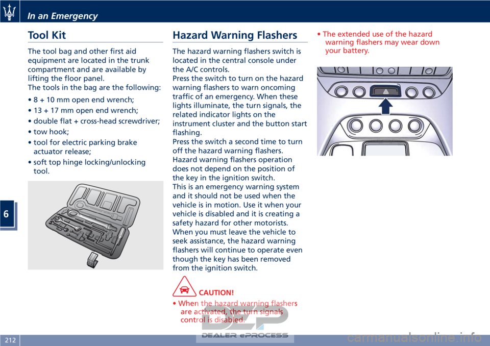
Tool Kit
The tool bag and other first aid
equipment are located in the trunk
compartment and are available by
lifting the floor panel.
The tools in the bag are the following:
•8+10mmopen end wrench;
• 13 + 17 mm open end wrench;
• double flat + cross-head screwdriver;
• tow hook;
• tool for electric parking brakeactuator release;
• soft top hinge locking/unlocking tool.
Hazard Warning Flashers
The hazard warning flashers switch is
located in the central console under
the A/C controls.
Press the switch to turn on the hazard
warning flashers to warn oncoming
traffic of an emergency. When these
lights illuminate, the turn signals, the
related indicator lights on the
instrument cluster and the button start
flashing.
Press the switch a second time to turn
off the hazard warning flashers.
Hazard warning flashers operation
does not depend on the position of
the key in the ignition switch.
This is an emergency warning system
and it should not be used when the
vehicle is in motion. Use it when your
vehicle is disabled and it is creating a
safety hazard for other motorists.
When you must leave the vehicle to
seek assistance, the hazard warning
flashers will continue to operate even
though the key has been removed
from the ignition switch.
CAUTION!
• When the hazard warning flashers are activated, the turn signals
control is disabled. • The extended use of the hazard
warning flashers may wear down
your battery.
In an Emergency
6
212
Page 217 of 296
In the Event of an
Accident
It is important always to keep calm.
• If not directly involved, stop at a safedistance of at least 10 yards away
from the accident area.
• If on a highway, stop without obstructing the emergency lane and
be especially careful if you need to
exit the vehicle.
• Turn off the engine and switch on the hazard warning flashers.
• At night, illuminate the accident area with the headlights.
• Always act with caution to avoid the risk of being crashed into by other
drivers.
• Indicate that an accident has occurred by placing the emergency
triangle (if equipped) in a well
visible position and at the prescribed
distance.
• Call the emergency services, providing as much information as
possible. On the highway, use the
special call boxes.
• Remove the ignition key (if present) from the vehicles involved.
• If fuel or other chemical products can be smelled, do not smoke and ask people around you to put their
cigarettes out.
• To extinguish fires, even small ones, use a fire extinguisher, blankets,
sand or earth. Never use water.
• In multiple accidents occurred on highways, particularly where
visibility is poor, there is a high risk
of being involved in other collisions.
Leave the vehicle immediately and
move away from the area.
In case of Injured Persons
• Never leave the injured personalone. Persons not directly involved
in the accident are also required to
give assistance.
• Do not crowd around injured persons.
• Reassure the injured person that help is on the way.
WARNING!
California Proposition 65
Operating, servicing and maintaining
a passenger vehicle or off-road vehicle
can expose you to chemicals including
such as, engine exhaust, carbon
monoxide, phthalates and lead, that
which are know to the State of
California to cause cancer and birth defects or other reproductive harm. To
minimize exposure, avoid breathing
exhaust, do not idle the engine except
as necessary, service your vehicle in a
well-ventilated area and wear gloves
or wash your hands frequently when
servicing your vehicle. For more
information go to:
www.P65Warnings.ca.gov/passenger-
vehicle
In an Emergency
6
213
Page 219 of 296
WARNING!
California Proposition 65
Operating, servicing and maintaining
a passenger vehicle or off-road vehicle
can expose you to chemicals including
such as, engine exhaust, carbon
monoxide, phthalates and lead, that
which are know to the State of
California to cause cancer and birth
defects or other reproductive harm. To
minimize exposure, avoid breathing
exhaust, do not idle the engine except
as necessary, service your vehicle in a
well-ventilated area and wear gloves
or wash your hands frequently when
servicing your vehicle.
NOTE:
For
the tire repair procedures with tire
repair kit see instructions included in
the kit.
This kit will provide a temporary tire
seal, allowing you to drive your
vehicle up to 6 miles (10 km) with a
maximum speed of 50 mph (80 km/h).
CAUTION!
• Intruding objects (e.g., screws or nails) should not be removed from the tire, which could compromise
the repair with the tire repair kit.
• Do not use the tire repair kit if the tire shows lateral damages and/or
the rim is damaged by driving with
flat tire.
• Tire repair kit can be used in outside temperatures down to
approximately -4°F (-20°C).
• Replace the tire repair kit sealant gas cylinder prior to the expiration date
(printed on the gas cylinder label) to
assure optimum operation of the
system.
NOTE:
• The
compressor power plug can be
inserted either in the 12 V power
outlet housed in the trunk or inside
the passenger compartment (see
“Interior Features” in section
“Understanding the Vehicle”).
• When having the tire serviced,
advise the Authorized Maserati
Dealer or service center that the tire
has been sealed using the tire repair
kit.
Using the Compact Spare
Wheel (for versions/markets
where provided)
Upon request, the vehicle may come
equipped with a compact spare wheel
(emergency wheel), jack and tools for
replacing a wheel.
The compact spare wheel is stored in
the trunk and housed in a bag: it is
supplied deflated in order to limit the
amount of space occupied. An electric
compressor is also provided for
inflating.
The bag covering the compact spare
wheel has a side pocket containing
the protective bag for the standard
wheel that has been removed along
with a pair of gloves.
In the event of a tire puncture,
proceed as follows.
• Stop the vehicle in a place that does not constitute a danger to traffic
and where the wheel can be
changed safely. The vehicle must be
level and on firm ground.
• Select the P (Park) mode and then engage manually the electric
parking brake and turn the key in
the ignition switch to STOP (OFF)
position.
In an Emergency
6
215
Page 221 of 296

• Remove from the compressor casethe inflation hose and the cable with
a plug for the power outlet.
• Unscrew the valve cap of the compact spare wheel and screw the
fitting of the inflation hose onto the
valve.
• Insert the plug in one of the available power outlets fitted in the
trunk or passenger compartment.
• Turn the key in the ignition switch in MAR (ON) position.
• Turn the compressor on by pressing the switch.
• Stop the compressor pressing switch again, when the pressure indicated
by the gage reaches the
recommended level (see “Tire
Inflation Pressure” in section
“Features and Specifications”) and
screw the cap on the compact spare
wheel valve.
CAUTION!
• In order to obtain a more accurate reading, the compressor should be
switched off when checking the tire
pressure of the compact spare wheel
on the pressure gage.
• Do not run the compressor for more than 20 minutes: there is a risk it
could overheat. Also, prolonged
power absorption may discharge the
battery, subsequently preventing the
engine from starting.
• The compressor has been designed exclusively to inflate compact spare
wheels; do not use it to inflate air
mattresses, dinghies etc.
• Fit the adapter on the wrench. Extend
the wrench as shown, then
loosen by approximately one turn, the five bolts on the wheel to be
changed.
• Open the jack partially, releasing and turning the control lever clockwise.
• Place the jack near the wheel to be changed in one of the indicated
positions.
• Make sure that the head of the jack is correctly inserted in one of the
slots beneath the sole bar.
In an Emergency
6
217