Page 297 of 575

2. Remove the cap and dipstick and wipeit with a clean, lint-free cloth.
3. Add fluid that meets the Fordspecifications. See Capacities andSpecifications (page 349). Pour the fluiddirectly into the automatic transmissionfluid cap and dipstick hole.
4.Replace the cap and dipstick and removeit again to check the fluid level.
5.Make sure that the fluid level is betweenthe MIN and the MAX marks.
6.Replace the automatic transmission fluidcap and dipstick. Turn it clockwise untilyou feel a strong resistance.
*Vehicles With Turbocharged Engines
WARNING: Do not start the enginewith the air filter removed. This can causedamage not covered by the vehicleWarranty and can result in serious injury.
1. Loosen the clamp holding the air filterassembly to the rubber hose.
2. Remove the air filter assembly securingbolts.
3. Lift the air filter assembly to disengagethe locating pins.
4.Rotate the air filter assembly slightly in acounterclockwise direction.
5. Check the transmission fluid level.
6. Install the air filter assembly in reverseorder. Tighten the air filter assemblysecuring bolts until you feel a strongresistance.
BRAKE FLUID CHECK
WARNING: Do not use any fluid otherthan the recommended brake fluid as thiswill reduce brake efficiency. Use ofincorrect fluid could result in the loss ofvehicle control, serious personal injury ordeath.
WARNING: Only use brake fluid froma sealed container. Contamination with dirt,water, petroleum products or othermaterials may result in brake systemdamage or failure. Failure to adhere to thiswarning could result in the loss of vehiclecontrol, serious personal injury or death.
WARNING: Do not allow the fluid totouch your skin or eyes. If this happens,rinse the affected areas immediately withplenty of water and contact your physician.
WARNING: A fluid level between theMAX and MIN lines is within the normaloperating range and there is no need toadd fluid. A fluid level not in the normaloperating range could compromise theperformance of the system. Have yourvehicle checked immediately.
294
MKT (TP4) , enUSA, Edition date: 201803, Second-Printing
Maintenance
Page 298 of 575

To avoid fluid contamination, the reservoircap must remain in place and fully tight,unless you are adding fluid.
Only use fluid that meets Ford specifications.See Capacities and Specifications (page343).
POWER STEERING FLUID CHECK
Your vehicle is equipped with an electricpower steering (EPS) system. There is nofluid reservoir to check or fill.
WASHER FLUID CHECK
WARNING: If you operate yourvehicle in temperatures below 41.0°F (5°C),use washer fluid with antifreeze protection.Failure to use washer fluid with antifreezeprotection in cold weather could result inimpaired windshield vision and increasethe risk of injury or accident.
Note:The front and rear washer systemsare supplied from the same reservoir.
Add fluid to fill the reservoir if the level is low.Only use a washer fluid that meets ourspecifications. See Capacities andSpecifications (page 343).
State or local regulations on volatile organiccompounds may restrict the use of methanol,a common windshield washer antifreezeadditive. Washer fluids containingnon-methanol antifreeze agents should beused only if they provide cold weatherprotection without damaging the vehicle’spaint finish, wiper blades or washer system.
CHANGING THE 12V BATTERY
WARNING: Batteries normallyproduce explosive gases which can causepersonal injury. Therefore, do not allowflames, sparks or lighted substances tocome near the battery. When working nearthe battery, always shield your face andprotect your eyes. Always provide correctventilation.
295
MKT (TP4) , enUSA, Edition date: 201803, Second-Printing
MaintenanceE170684
Page 299 of 575

WARNING: When lifting aplastic-cased battery, excessive pressureon the end walls could cause acid to flowthrough the vent caps, resulting in personalinjury and damage to the vehicle or battery.Lift the battery with a battery carrier or withyour hands on opposite corners.
WARNING: Keep batteries out ofreach of children. Batteries contain sulfuricacid. Avoid contact with skin, eyes orclothing. Shield your eyes when workingnear the battery to protect against possiblesplashing of acid solution. In case of acidcontact with skin or eyes, flush immediatelywith water for a minimum of 15 minutes andget prompt medical attention. If acid isswallowed, call a physician immediately.
WARNING: Battery posts, terminalsand related accessories contain lead andlead compounds. Wash hands afterhandling.
WARNING: For vehicles withAuto-Start-Stop the battery requirement isdifferent. You must replace the battery withone of exactly the same specification.
Your vehicle is fitted with a Motorcraftmaintenance-free battery which normallydoes not require additional water.
When a battery replacement is required, youmust use a recommended replacementbattery that matches the electricalrequirements of the vehicle.
Note:If your vehicle has a battery cover,after cleaning or replacing the battery, makesure you reinstall it.
Note:See an authorized dealer for batteryaccess, testing, or replacement.
To make sure the battery managementsystem works correctly, do not connect anelectrical device ground connection directlyto the battery negative post. This can causeinaccurate measurements of the batterycondition and potential incorrect systemoperation.
Note:If you add electrical accessories orcomponents to the vehicle, it may adverselyaffect battery performance and durability.This may also affect the performance ofother electrical systems in the vehicle.
If you see any corrosion on the battery orterminals, remove the cables from theterminals and clean with a wire brush. Youcan neutralize the acid with a solution ofbaking soda and water.
Because your vehicle’s engine iselectronically-controlled by a computer,some engine control settings are maintainedby power from the battery. Some enginecomputer settings, like the idle trim and fueltrim strategy, optimize the driveability andperformance of the engine. The clock andradio station presets are also maintained inmemory by power from the low-voltagebattery. These settings are erased when atechnician disconnects and connects thelow-voltage battery.
To restore the settings, do the following:
296
MKT (TP4) , enUSA, Edition date: 201803, Second-Printing
Maintenance
Page 300 of 575

Note:Until you switch the ignition to the onposition, you will receive a message in yourinformation display stating that your vehicleis not in park.
1. Apply the parking brake.
2. Shift into park (P) or neutral (N).
3. Switch off all accessories.
4. Press the brake pedal and start yourvehicle.
5. Run the engine until it reaches normaloperating temperature. While the engineis warming up, complete the following:Reset the clock. See Audio Unit (page366). Reset the power windowsbounce-back feature. See PowerWindows (page 94). Reset the radiostation presets. See Audio Unit (page366).
6. Allow the engine to idle for at least oneminute.
7.Drive the vehicle at least 10 mi (16 km) tocompletely relearn the idle trim and fueltrim strategy.
Note:If you do not allow the engine torelearn the idle and fuel trim strategy, theidle quality of your vehicle may be adverselyaffected until the engine computereventually relearns the idle trim and fuel trimstrategy.
Note:Certain features may not operate ifthe battery monitor system is not reset witha scan tool following a jump start or batteryreplacement. Normal electrical accessoryoperation should resume after your vehicleis left undisturbed for 8 hours.
Make sure that you dispose of old batteriesin an environmentally friendly way. Seekadvice from your local authority aboutrecycling old batteries.
If storing your vehicle for more than 30 dayswithout recharging the battery, werecommend that you disconnect the batterycables to maintain battery charge for quickstarting.
CHECKING THE WIPER BLADES
Run the tip of your fingers over the edge ofthe blade to check for roughness.
Clean the wiper blades with washer fluid orwater applied with a soft sponge or cloth.
CHANGING THE WIPER BLADES
You can improve poor wiper quality bycleaning the wiper blades and thewindshield.
Replace the wiper blades at least annuallyfor optimum performance.
297
MKT (TP4) , enUSA, Edition date: 201803, Second-Printing
MaintenanceE142463
Page 301 of 575

Front Wiper Blades
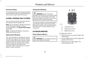
1. Lift the wiper arm and then press thewiper blade locking buttons together.
Note:Do not hold the wiper blade whenlifting the wiper arm.
Note:Make sure that the wiper arm doesnot spring back against the glass when thewiper blade is not attached.
2. Slightly rotate the wiper blade.
3. Remove the wiper blade.
4. Install in the reverse order.
Note:Make sure that the wiper blade locksinto place.
Rear Window Wiper Blade
1. Lift the wiper arm.
Note:Do not hold the wiper blade whenlifting the wiper arm.
Note:Make sure that the wiper arm doesnot spring back against the glass when thewiper blade is not attached.
2. Remove the wiper blade.
Note:Make sure that the wiper blade locksinto place.
ADJUSTING THE HEADLAMPS
Vertical Aim Adjustment
The assembly plant properly aims theheadlamps on your vehicle. If your vehiclehas been in an accident, have the alignmentof your headlamps checked by yourauthorized dealer.
8 feet (2.4 meters)A
Center height of lamp to groundB
298
MKT (TP4) , enUSA, Edition date: 201803, Second-Printing
MaintenanceE129990
1
1 2 E183236 E142592
Page 302 of 575

25 feet (7.6 meters)C
Horizontal reference lineD
1.Park the vehicle directly in front of a wallor screen on a level surface,approximately 25 ft (7.6 m) away.
2.Measure the height of the headlamp bulbcenter from the ground and mark an 8 ft(2.4 m) horizontal reference line on thevertical wall or screen at this height.
Note:To see a clearer light pattern foradjusting, you may want to block the lightfrom one headlamp while adjusting theother.
3. Switch on the low beam headlamps tolight the wall or screen and open thehood.
4. On the wall or screen, you will observea flat zone of high intensity light locatedat the top of the right hand portion of thebeam pattern. If the top edge of the highintensity light zone is not at the horizontalreference line, you will need to adjust theheadlamp.
5. Locate the vertical adjuster on eachheadlamp. Turn the adjuster eitherclockwise or counterclockwise in orderto aim the headlamp.
6.Close the hood and switch off the lamps.
Horizontal Aim Adjustment
Horizontal aim is not required for this vehicleand is non-adjustable.
299
MKT (TP4) , enUSA, Edition date: 201803, Second-Printing
MaintenanceE142465 E171165
Page 303 of 575

REMOVING A HEADLAMP
To gain access to the headlamp securingbolts and to remove the headlamp assembly,you must first remove the front fascia andfront bumper assemblies. We recommendyou see an authorized dealer.
CHANGING A BULB
WARNING: Switch the lamps and theignition off. Failure to do so could result inserious personal injury.
WARNING: Bulbs can become hot.Let the bulb cool down before removingit. Failure to do so could result in personalinjury.
Use the correct specification bulb. See BulbSpecification Chart (page 362).
Install in the reverse order unless otherwisestated.
High Intensity Discharge Headlamp
These lamps operate at a high voltage. Seean authorized dealer if they fail.
Front Fog Lamp
1. Switch all of the lamps and the ignitionoff.
2. Use suitable tools, for example ascrewdriver and a socket wrench toremove the four screws from the wheelarch liner.
3. You can now carefully reposition thewheel arch liner to allow access to thefront fog lamp bulb and electricalconnector.
4. Disconnect the electrical connector.
5. Turn the bulb holder counterclockwiseand remove it.
Note:You cannot separate the bulb fromthe bulb holder.
Note:Do not touch the bulb glass.
300
MKT (TP4) , enUSA, Edition date: 201803, Second-Printing
MaintenanceE220461 E174588
Page 304 of 575

Front Direction Indicator Lamp
If a front direction indicator lamp fails, seean authorized dealer.
LED Lamps
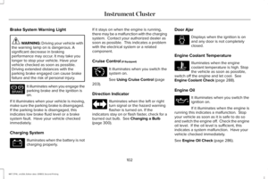
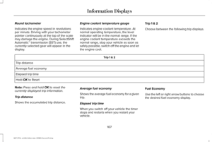
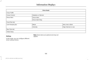
LED lamps are not serviceable items. Seean authorized dealer if they fail.
The following lamps are LED:
•Side direction indicators.
•Approach lamp.
•Brake and rear lamps.
•Rear direction indicators.
•Rear side marker lamps.
•Reversing lamps.
•Central high mounted brake lamp.
•Front side marker lamps.
•Front parking lamps.
License Plate Lamp
1. Switch all of the lamps and the ignitionoff.
2.Remove the screws that secure the lensto the lamp housing.
3. Remove the lamp lens.
4.Remove the bulb by pulling it straight out.
CHANGING THE ENGINE AIR
FILTER
WARNING: To reduce the risk ofvehicle damage and personal burn injuries,do not start your engine with the aircleaner removed and do not remove itwhile the engine is running.
When changing the engine air filter, do notallow debris or foreign material to enter theair induction system. Engine components aresusceptible to damage not covered by thevehicle Warranty.
Change the air filter element at the correctinterval. See Scheduled Maintenance (page479).
Incorrect component use can cause damagenot covered by the vehicle Warranty. SeeMotorcraft Parts (page 345).
To replace the air filter element do thefollowing:
301
MKT (TP4) , enUSA, Edition date: 201803, Second-Printing
MaintenanceE2206171
2
3