Page 7 of 626

described for technical and/or commercial reasons. For
further information, contact an authorized dealer.
If applicable, refer to the Owner ’s Manual Supplement for
related information.
NOTE:After reviewing the Owner ’s Information, it should
be stored in the vehicle for convenient referencing, and
remain with the vehicle when sold.
When it comes to service, remember that your authorized
dealer knows your vehicle best, has factory-trained techni-
cians and genuine MOPAR® parts, and cares about your
satisfaction.
HOW TO USE THIS MANUAL
Essential Information
Consult the Table of Contents to determine which section
contains the information you desire.
Since the specification of your vehicle depends on the items
of equipment ordered, certain descriptions and illustra-
tions may differ from your vehicle’s equipment.
The detailed index at the back of this Owner’s Manual
contains a complete listing of all subjects.
Symbols
Some vehicle components have colored labels whose sym-
bols indicate precautions to be observed when using this
component. Refer to “Warning Lights and Messages” in
“Getting To Know Your Instrument Panel” for further
information on the symbols used in your vehicle.
ROLLOVER WARNING
Utility vehicles have a significantly higher rollover rate
than other types of vehicles. This vehicle has a higher
ground clearance and a higher center of gravity than many
passenger vehicles. It is capable of performing better in a
wide variety of off-road applications. Driven in an unsafe
manner, all vehicles can go out of control. Because of the
higher center of gravity, if this vehicle is out of control it
may roll over while some other vehicles may not.
Do not attempt sharp turns, abrupt maneuvers, or other
unsafe driving actions that can cause loss of vehicle con-
trol. Failure to operate this vehicle safely may result in a
collision, rollover of the vehicle, and severe or fatal injury.
Drive carefully.
1
INTRODUCTION 5
Page 58 of 626
WARNING!(Continued)
•Do not place anything on the seat or seatback that
insulates against heat, such as a blanket or cushion.
This may cause the seat heater to overheat. Sitting in
a seat that has been overheated could cause serious
burns due to the increased surface temperature of the
seat.
Rear Heated Seats — If Equipped
On some models, the two rear outboard seats may be
equipped with heated seats. There are two heated seat
switches that allow the rear passengers to operate the seats
independently. The heated seat switches for each heater are
located on the rear of the center console. You can choose from HI, LO, or OFF heat settings. Amber
indicator lights in each switch indicate the level of heat in
use. Two indicator lights will illuminate for HI, one for LO
and none for OFF.
•
Push the switch
once to turn the HI setting on.
•Push the switcha second time to turn the LO
setting on.
• Push the switcha third time to turn the heating
elements off.
Page 131 of 626

WARNING!(Continued)
•Close the lid when not in use and while driving the
vehicle.
• If this outlet is mishandled, it may cause an electric
shock and failure.
CAUTION!
•Many accessories that can be plugged in draw power
from the vehicle’s battery, even when not in use (i.e.,
cellular phones, etc.). Eventually, if plugged in long
enough, the vehicle’s battery will discharge suffi-
ciently to degrade battery life and/or prevent the
engine from starting.
• Accessories that draw higher power (i.e., coolers,
vacuum cleaners, lights, etc.) will degrade the battery
even more quickly. Only use these intermittently and
with greater caution.
• After the use of high power draw accessories, or long
periods of the vehicle not being started (with acces-
sories still plugged in), the vehicle must be driven a
sufficient length of time to allow the generator to
recharge the vehicle’s battery.
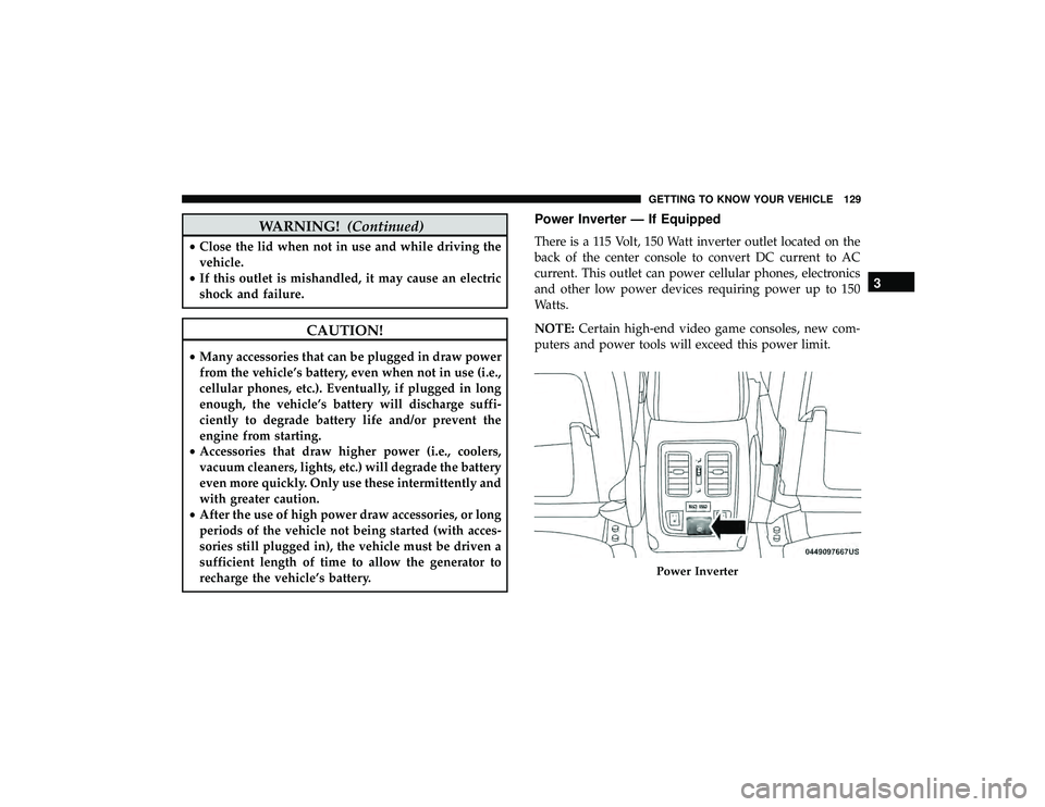
Power Inverter — If Equipped
There is a 115 Volt, 150 Watt inverter outlet located on the
back of the center console to convert DC current to AC
current. This outlet can power cellular phones, electronics
and other low power devices requiring power up to 150
Watts.
NOTE: Certain high-end video game consoles, new com-
puters and power tools will exceed this power limit.
Page 141 of 626

Secondary Method For Oil Change Reset Procedure
1. Without pushing the brake pedal, place the ignition inthe ON/RUN position (do not start the engine).
2. Fully press the accelerator pedal, slowly, three times within ten seconds.
3. Without pushing the brake pedal, place the ignition in the OFF/LOCK position.
NOTE: If the indicator message illuminates when you
start the vehicle, the oil change indicator system did not
reset. If necessary, repeat this procedure.
Instrument Cluster Display Messages
Includes the following, but not limited to:
• Front Seatbelts Unbuckled
• Driver Seat Belt Unbuckled
• Passenger Seat Belt Unbuckled
• Traction Control Off
• Washer Fluid Low
• Oil Pressure Low
• Oil Change Due •
Fuel Low
• Service Anti-lock Brake System
• Service Electronic Throttle Control
• Service Power Steering
• Cruise Control Off
• Cruise Control Ready
• ACC Driver Override
• Cruise Control Set To XXX MPH
• Tire Pressure Screen With Low Tire(s) “Inflate Tire to
XX”
• Service Tire Pressure System
• Speed Warning Set To XXX MPH
• Speed Warning Exceeded
• Parking Brake Engaged
• Brake Fluid Low
• Service Electronic Braking System
• Engine Temperature Hot
• Lights On
4
GETTING TO KNOW YOUR INSTRUMENT PANEL 139
Page 143 of 626

•Vehicle Cannot Be Lowered Door Open
• Air Suspension Temporarily Disabled
• Battery Low Start Engine To Change Ride Height
For further information on the color warning and indicator
lights in the instrument cluster, refer to “Warning Lights
And Messages” in “Getting To Know Your Instrument
Panel”.
Instrument Cluster Display Menu Items
The instrument cluster display can be used to view the
main menu items for several features. Use the upand
down arrow buttons to scroll through the driver interactive
display menu options until the desired menu is reached.
NOTE: Depending on the vehicle’s options, feature set-
tings may vary.
Speedometer
Push and release the upordown arrow button until the
main gauge menu icon is displayed in the instrument
cluster display. Push and release the leftorright arrow
button to select the analog or digital type speedometer
display. Push and release the OKbutton to toggle units
(mph or km/h) of the speedometer.
Accessibility — If Equipped
Accessibility is a feature of the DVD/Blu-ray system that
announces a function prior to performing the action. For
further information refer to “Uconnect Settings” in “Mul-
timedia.”
Vehicle Info
Push and release the upordown arrow button until the
Vehicle Info menu icon is displayed in the instrument
cluster display. Push and release the leftorright arrow
button to scroll through the information submenus and
push and release the OKbutton to select or reset the
resettable submenus.
Page 148 of 626

•Trip Info (show/hide)
• Stop/Start
• Audio (show/hide)
• Messages
• Screen Setup
The menu with (show/hide) means user can press OK
button to choose show or hide this menu on the instrument
cluster display.
Battery Saver On/Battery Saver Mode Message —
Electrical Load Reduction Actions (If Equipped)
This vehicle is equipped with an Intelligent Battery Sensor
(IBS) to perform additional monitoring of the electrical
system and status of the vehicle battery.
In cases when the IBS detects charging system failure, or
the vehicle battery conditions are deteriorating, electrical
load reduction actions will take place to extend the driving
time and distance of the vehicle. This is done by reducing
power to or turning off non-essential electrical loads. Load reduction is only active when the engine is running.
It will display a message if there is a risk of battery
depletion to the point where the vehicle may stall due to
lack of electrical supply, or will not restart after the current
drive cycle.
When load reduction is activated, the message “Battery
Saver On” or “Battery Saver Mode” will appear in the
instrument cluster display.
These messages indicate the vehicle battery has a low state
of charge and continues to lose electrical charge at a rate
that the charging system cannot sustain.
NOTE:
•
The charging system is independent from load reduc-
tion. The charging system performs a diagnostic on the
charging system continuously.
• If the Battery Charge Warning Light is on it may indicate
a problem with the charging system. Refer to “Battery
Charge Warning Light” in “Warning Lights And Mes-
sages” located in ”Getting To Know Your Instrument
Panel” for further information.
146 GETTING TO KNOW YOUR INSTRUMENT PANEL
Page 151 of 626
WARNING LIGHTS AND MESSAGES
The warning/indicator lights will illuminate in the instru-
ment panel together with a dedicated message and/or
acoustic signal when applicable. These indications are
indicative and precautionary and as such must not be
considered as exhaustive. Always refer to the information
in this chapter in the event of a failure indication. All active
telltales will display first if applicable. The system check
menu may appear different based upon equipment options
and current vehicle status. Some telltales are optional and
may not appear.
Red Warning Lights
Page 155 of 626
— Transmission Temperature Warning Light — If
Equipped
This warning light will illuminate to warn of a high
transmission fluid temperature. This may occur with
strenuous usage such as trailer towing. If this light turns
on, stop the vehicle and run the engine at idle or slightly
faster, with the transmission in PARK or NEUTRAL, until
the light turns off. Once the light turns off, you may
continue to drive normally.
CAUTION!
Continuous driving with the Transmission Tempera-
ture Warning Light illuminated will eventually cause
severe transmission damage or transmission failure.
— Vehicle Security Warning Light — If Equipped
This light will flash at a fast rate for approximately 15
seconds when the vehicle security alarm is arming, and
then will flash slowly until the vehicle is disarmed.
Yellow Warning Lights