2019 JEEP GRAND CHEROKEE LIMITED wheel torque
[x] Cancel search: wheel torquePage 161 of 626
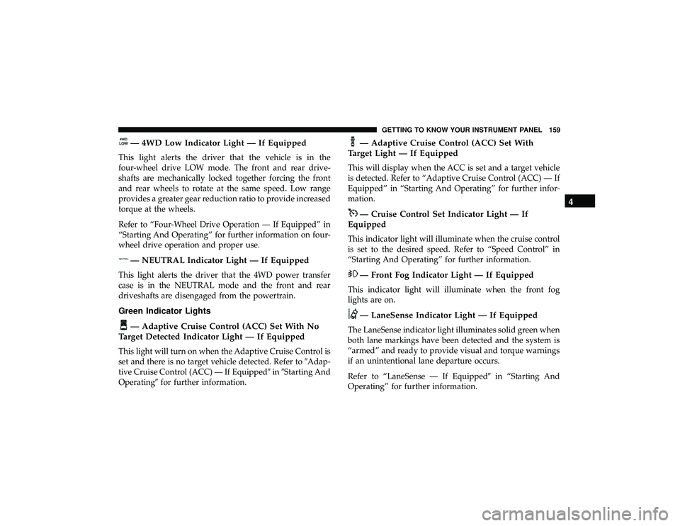
— 4WD Low Indicator Light — If Equipped
This light alerts the driver that the vehicle is in the
four-wheel drive LOW mode. The front and rear drive-
shafts are mechanically locked together forcing the front
and rear wheels to rotate at the same speed. Low range
provides a greater gear reduction ratio to provide increased
torque at the wheels.
Refer to “Four-Wheel Drive Operation — If Equipped” in
“Starting And Operating” for further information on four-
wheel drive operation and proper use.
Page 169 of 626
WARNING!(Continued)
•The capabilities of an ABS equipped vehicle must
never be exploited in a reckless or dangerous manner
that could jeopardize the user ’s safety or the safety of
others.
ABS is designed to function with the OEM tires. Modifica-
tion may result in degraded ABS performance.
Anti-Lock Brake Warning Light
The yellow “Anti-Lock Brake Warning Light” will turn on
when the ignition is turned to the ON/RUN mode and
may stay on for as long as four seconds.
If the “Anti-Lock Brake Warning Light” remains on or
comes on while driving, it indicates that the anti-lock
portion of the brake system is not functioning and that
service is required. However, the conventional brake sys-
tem will continue to operate normally if the “Anti-Lock
Brake Warning Light” is on.
If the “Anti-Lock Brake Warning Light” is on, the brake
system should be serviced as soon as possible to restore the
benefits of anti-lock brakes. If the “Anti-Lock Brake Warn-
ing Light” does not come on when the ignition is turned to
the ON/RUN mode, have the light repaired as soon as
possible.
Electronic Brake Control System
Your vehicle is equipped with an advanced Electronic
Brake Control system (EBC). This system includes Elec-
tronic Brake Force Distribution (EBD), Anti-Lock Brake
System (ABS), Brake Assist System (BAS), Hill Start Assist
(HSA), Traction Control System (TCS), Electronic Stability
Control (ESC), and Electronic Roll Mitigation (ERM). These
systems work together to enhance both vehicle stability
and control in various driving conditions.
Your vehicle may also be equipped with Trailer Sway
Control (TSC), Ready Alert Braking (RAB), Rain Brake
Support (RBS), Dynamic Steering Torque (DST), Hill De-
scent Control (HDC), and Selec-Speed Control (SSC).
Electronic Brake Force Distribution (EBD)
This function manages the distribution of the braking
torque between the front and rear axles by limiting braking
pressure to the rear axle. This is done to prevent overslip of
the rear wheels to avoid vehicle instability, and to prevent
the rear axle from entering ABS before the front axle.
Brake System Warning Light
The red “Brake System Warning Light” will turn on when
the ignition is turned to the ON/RUN mode and may stay
on for as long as four seconds.
5
SAFETY 167
Page 178 of 626
NOTE:The DST feature is only meant to help the driver
realize the correct course of action through small torques
on the steering wheel, which means the effectiveness of the
DST feature is highly dependent on the driver ’s sensitivity
and overall reaction to the applied torque. It is very
important to realize that this feature will not steer the
vehicle, meaning the driver is still responsible for steering
the vehicle.
Hill Descent Control (HDC) — If Equipped
HDC is intended for low speed off road driving while in
4WD Low Range. HDC maintains vehicle speed while
descending hills during various driving situations. HDC
controls vehicle speed by actively controlling the brakes.
HDC Has Three States:
1. Off (feature is not enabled and will not activate).
2. Enabled (feature is enabled and ready but activation conditions are not met, or driver is actively overriding
with brake or throttle application).
3. Active (feature is enabled and actively controlling ve- hicle speed). Enabling HDC
HDC is enabled by pushing the HDC switch, but the
following conditions must also be met to enable HDC:
•
Driveline is in 4WD Low Range.
• Vehicle speed is below 5 mph (8 km/h).
• Parking brake is released.
• Driver door is closed.
Activating HDC
Once HDC is enabled it will activate automatically if
driven down a grade of sufficient magnitude. The set speed
for HDC is selectable by the driver, and can be adjusted by
using the gear shift +/-. The following summarizes the
HDC set speeds:
HDC Target Set Speeds
• P = No set speed. HDC may be enabled but will not
activate.
• R = 0.6 mph (1 km/h)
• N = 1.2 mph (2 km/h)
176 SAFETY
Page 275 of 626
FOUR WHEEL DRIVE OPERATION
Quadra-Trac I Operating Instructions/Precautions
— If Equipped
The Quadra-Trac I is a single-speed (HI range only) trans-
fer case, which provides convenient full-time four-wheel
drive. No driver interaction is required. The Brake Traction
Control (BTC) System, which combines standard ABS and
Traction Control, provides resistance to any wheel that is
slipping to allow additional torque transfer to wheels with
traction.
NOTE:The Quadra-Trac I system is not appropriate for
conditions where 4WD LOW range is recommended. Refer
to “Off-Road Driving Tips” in “Starting And Operating”
Quadra-Trac II Operating Instructions/Precautions
— If Equipped
The Quadra-Trac II transfer case is fully automatic in the
normal driving 4WD AUTO mode. The Quadra-Trac II
transfer case provides three mode positions:
• 4WD HI
• NEUTRAL
• 4WD LOW This transfer case is fully automatic in the 4WD HI mode.
When additional traction is required, the 4WD LOW
position can be used to lock the front and rear driveshafts
together and force the front and rear wheels to rotate at the
same speed. The 4WD LOW position is intended for loose,
slippery road surfaces only. Driving in the 4WD LOW
position on dry, hard-surfaced roads may cause increased
tire wear and damage to driveline components.
When operating your vehicle in 4WD LOW, the engine
speed is approximately three times that of the 4WD HI
position at a given road speed. Take care not to overspeed
the engine and do not exceed 25 mph (40 km/h).
Proper operation of four-wheel drive vehicles depends on
tires of equal size, type, and circumference on each wheel.
Any difference will adversely affect shifting and cause
damage to the transfer case.
Because four-wheel drive provides improved traction,
there is a tendency to exceed safe turning and stopping
speeds. Do not go faster than road conditions permit.
6
STARTING AND OPERATING 273
Page 281 of 626
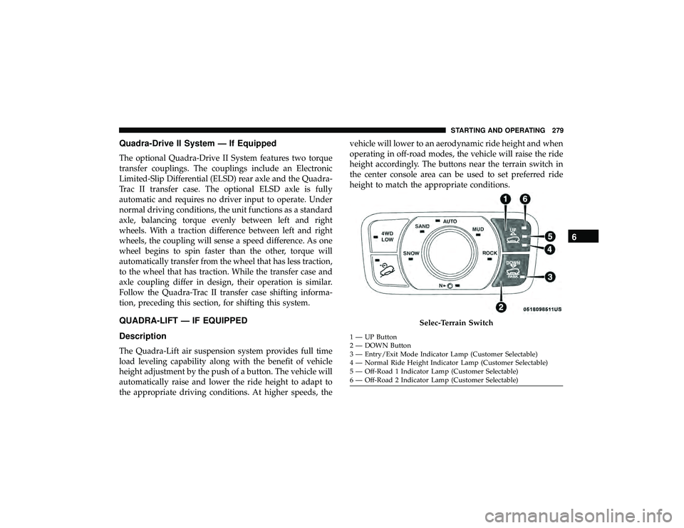
Quadra-Drive II System — If Equipped
The optional Quadra-Drive II System features two torque
transfer couplings. The couplings include an Electronic
Limited-Slip Differential (ELSD) rear axle and the Quadra-
Trac II transfer case. The optional ELSD axle is fully
automatic and requires no driver input to operate. Under
normal driving conditions, the unit functions as a standard
axle, balancing torque evenly between left and right
wheels. With a traction difference between left and right
wheels, the coupling will sense a speed difference. As one
wheel begins to spin faster than the other, torque will
automatically transfer from the wheel that has less traction,
to the wheel that has traction. While the transfer case and
axle coupling differ in design, their operation is similar.
Follow the Quadra-Trac II transfer case shifting informa-
tion, preceding this section, for shifting this system.
QUADRA-LIFT — IF EQUIPPED
Description
The Quadra-Lift air suspension system provides full time
load leveling capability along with the benefit of vehicle
height adjustment by the push of a button. The vehicle will
automatically raise and lower the ride height to adapt to
the appropriate driving conditions. At higher speeds, thevehicle will lower to an aerodynamic ride height and when
operating in off-road modes, the vehicle will raise the ride
height accordingly. The buttons near the terrain switch in
the center console area can be used to set preferred ride
height to match the appropriate conditions.
Page 355 of 626
When both lane markings are detected and the driver
unintentionally drifts out of the lane (no turn signal
applied), the LaneSense system provides a haptic warning
in the form of torque applied to the steering wheel to
prompt the driver to remain within the lane boundaries. If
the driver continues to unintentionally drift out of the lane,
the LaneSense system provides a visual warning through
the instrument cluster display to prompt the driver to
remain within the lane boundaries.
The driver may manually override the haptic warning by
applying torque into the steering wheel at any time.
When only a single lane marking is detected and the driver
unintentionally drifts across the lane marking (no turn
signal applied), the LaneSense system provides visual
warnings through the instrument cluster display to prompt
the driver to remain within the lane. When only a single
lane marking is detected, a haptic (torque) warning will not
be provided.
NOTE:When operating conditions have been met, the
LaneSense system will monitor if the driver ’s hands are on
the steering wheel and provides an audible warning to the
driver when the driver ’s hands are not detected on the
steering wheel. The system will cancel if the driver does
not return their hands to the wheel.Turning LaneSense On Or Off
The default status of LaneSense is off. The LED in Lane-
Sense button will be illuminated while the system is
deactivated.
The LaneSense button is located on the switch
panel below the Uconnect display.
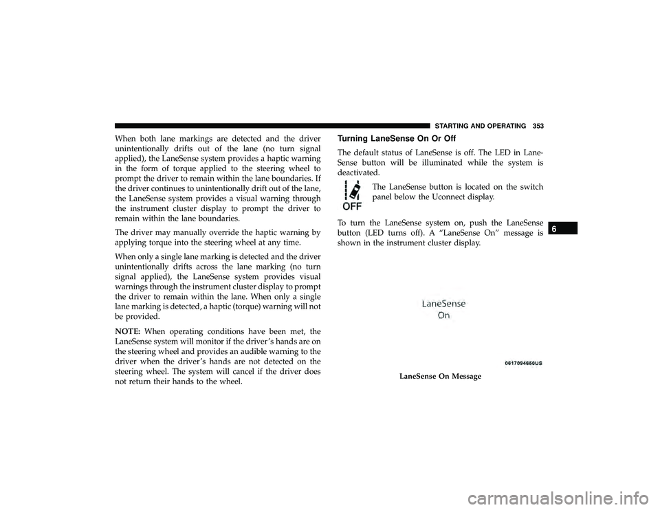
To turn the LaneSense system on, push the LaneSense
button (LED turns off). A “LaneSense On” message is
shown in the instrument cluster display.
Page 357 of 626
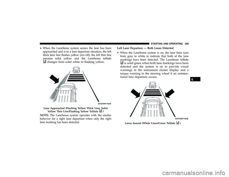
•When the LaneSense system senses the lane has been
approached and is in a lane departure situation, the left
thick lane line flashes yellow (on/off), the left thin line
remains solid yellow and the LaneSense telltale
changes from solid white to flashing yellow.
NOTE: The LaneSense system operates with the similar
behavior for a right lane departure when only the right
lane marking has been detected. Left Lane Departure — Both Lanes Detected
•
When the LaneSense system is on, the lane lines turn
from gray to white to indicate that both of the lane
markings have been detected. The LaneSense telltale
is solid green when both lane markings have been
detected and the system is on to provide visual
warnings in the instrument cluster display and a
torque warning in the steering wheel if an uninten-
tional lane departure occurs.
)
Lanes Sensed (White Lines/Green Telltale)
6
STARTING AND OPERATING 355
Page 358 of 626
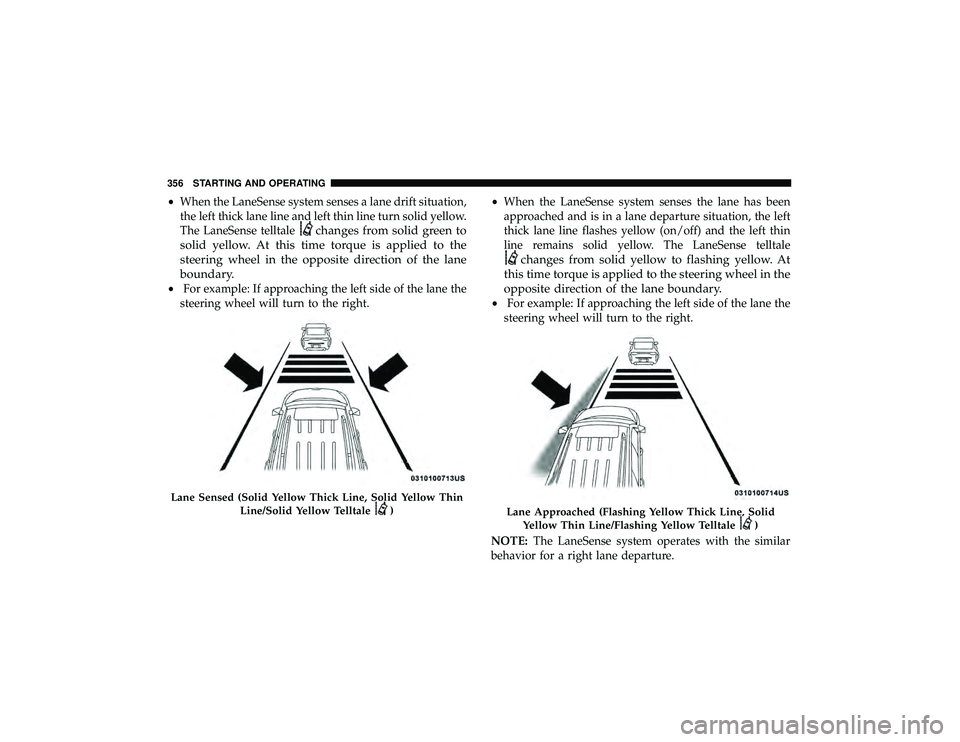
•When the LaneSense system senses a lane drift situation,
the left thick lane line and left thin line turn solid yellow.
The LaneSense telltale
changes from solid green to
solid yellow. At this time torque is applied to the
steering wheel in the opposite direction of the lane
boundary.
• For example: If approaching the left side of the lane the
steering wheel will turn to the right. •
When the LaneSense system senses the lane has been
approached and is in a lane departure situation, the left
thick lane line flashes yellow (on/off) and the left thin
line remains solid yellow. The LaneSense telltale
changes from solid yellow to flashing yellow. At
this time torque is applied to the steering wheel in the
opposite direction of the lane boundary.
• For example: If approaching the left side of the lane the
steering wheel will turn to the right.
NOTE: The LaneSense system operates with the similar
behavior for a right lane departure.
)Lane Approached (Flashing Yellow Thick Line, Solid
Yellow Thin Line/Flashing Yellow Telltale
)
356 STARTING AND OPERATING