2019 JEEP GRAND CHEROKEE LIMITED ECO mode
[x] Cancel search: ECO modePage 275 of 626
FOUR WHEEL DRIVE OPERATION
Quadra-Trac I Operating Instructions/Precautions
— If Equipped
The Quadra-Trac I is a single-speed (HI range only) trans-
fer case, which provides convenient full-time four-wheel
drive. No driver interaction is required. The Brake Traction
Control (BTC) System, which combines standard ABS and
Traction Control, provides resistance to any wheel that is
slipping to allow additional torque transfer to wheels with
traction.
NOTE:The Quadra-Trac I system is not appropriate for
conditions where 4WD LOW range is recommended. Refer
to “Off-Road Driving Tips” in “Starting And Operating”
Quadra-Trac II Operating Instructions/Precautions
— If Equipped
The Quadra-Trac II transfer case is fully automatic in the
normal driving 4WD AUTO mode. The Quadra-Trac II
transfer case provides three mode positions:
• 4WD HI
• NEUTRAL
• 4WD LOW This transfer case is fully automatic in the 4WD HI mode.
When additional traction is required, the 4WD LOW
position can be used to lock the front and rear driveshafts
together and force the front and rear wheels to rotate at the
same speed. The 4WD LOW position is intended for loose,
slippery road surfaces only. Driving in the 4WD LOW
position on dry, hard-surfaced roads may cause increased
tire wear and damage to driveline components.
When operating your vehicle in 4WD LOW, the engine
speed is approximately three times that of the 4WD HI
position at a given road speed. Take care not to overspeed
the engine and do not exceed 25 mph (40 km/h).
Proper operation of four-wheel drive vehicles depends on
tires of equal size, type, and circumference on each wheel.
Any difference will adversely affect shifting and cause
damage to the transfer case.
Because four-wheel drive provides improved traction,
there is a tendency to exceed safe turning and stopping
speeds. Do not go faster than road conditions permit.
6
STARTING AND OPERATING 273
Page 279 of 626
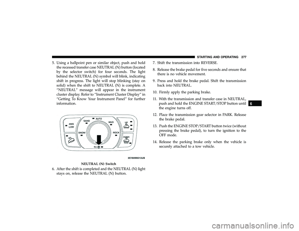
5. Using a ballpoint pen or similar object, push and holdthe recessed transfer case NEUTRAL (N) button (located
by the selector switch) for four seconds. The light
behind the NEUTRAL (N) symbol will blink, indicating
shift in progress. The light will stop blinking (stay on
solid) when the shift to NEUTRAL (N) is complete. A
“NEUTRAL” message will appear in the instrument
cluster display. Refer to “Instrument Cluster Display” in
“Getting To Know Your Instrument Panel” for further
information.
6. After the shift is completed and the NEUTRAL (N) light stays on, release the NEUTRAL (N) button. 7. Shift the transmission into REVERSE.
8. Release the brake pedal for five seconds and ensure that
there is no vehicle movement.
9. Press and hold the brake pedal. Shift the transmission back into NEUTRAL.
10. Firmly apply the parking brake.
11. With the transmission and transfer case in NEUTRAL, push and hold the ENGINE START/STOP button until
the engine turns off.
12. Place the transmission gear selector in PARK. Release the brake pedal.
13. Push the ENGINE STOP/START button twice (without pressing the brake pedal), to turn the ignition to the
OFF mode.
14. Release the parking brake only when the vehicle is securely attached to a tow vehicle.
Page 282 of 626
•Normal Ride Height (NRH) – This is the standard
position of the suspension and is meant for normal
driving.
• Off-Road 1 (OR1) (Raises the vehicle approximately
1.1 inches (28 mm)) – This is the primary position for all
off-road driving until OR2 is needed. A smoother and
more comfortable ride will result. Push the “UP” button
once from the NRH position while the vehicle speed is
below 38 mph (61 km/h). When in the OR1 position, if
the vehicle speed remains between 40 mph (64 km/h)
and 50 mph (80 km/h) for greater than 20 seconds or if
the vehicle speed exceeds 50 mph (80 km/h), the vehicle
will be automatically lowered to NRH. Refer to “Driving
Tips” in “Starting And Operating” for further informa-
tion.
• Off-Road 2 (OR2) (Raises the vehicle approximately
2.2 inches (55 mm)) – This position is intended for
off-roading use only where maximum ground clearance
is required. To enter OR2, push the “UP” button twice
from the NRH position or once from the OR1 position
while vehicle speed is below 20 mph (32 km/h). While
in OR2, if the vehicle speed exceeds 25 mph (40 km/h)
the vehicle height will be automatically lowered to OR1.
Refer to “Driving Tips” in “Starting And Operating” for
further information. •
Aero Mode (Lowers the vehicle approximately
0.6 inches (15 mm)) – This position provides improved
aerodynamics by lowering the vehicle. The vehicle will
automatically enter Aero Mode when the vehicle speed
remains between 52 mph (83 km/h) and 56 mph
(90 km/h) for greater than 20 seconds or if the vehicle
speed exceeds 56 mph (90 km/h). The vehicle will return
to NRH from Aero Mode if the vehicle speed remains
between 20 mph (32 km/h) and 25 mph (40 km/h) for
greater than 20 seconds or if the vehicle speed falls
below 20 mph (32 km/h). The vehicle will enter Aero
Mode, regardless of vehicle speed if the vehicle is in
“SPORT” mode.
• Entry/Exit Mode (Lowers the vehicle approximately
1.6 inches (40 mm) – This position lowers the vehicle for
easier passenger entry and exit as well as lowering the
rear of the vehicle for easier loading and unloading of
cargo. To enter Entry/Exit Mode, push the “DOWN”
button once from (NRH) while the vehicle speed is
below 25 mph (40 km/h). Once the vehicle speed goes
below 15 mph (24 km/h) the vehicle height will begin to
lower. If the vehicle speed remains between 15 mph
(24 km/h) and 25 mph (40 km/h) for greater than 60
seconds, or the vehicle speed exceeds 25 mph (40 km/h)
the Entry/Exit Mode change will be cancelled. To exit
280 STARTING AND OPERATING
Page 287 of 626
SELEC-TERRAIN — IF EQUIPPED
Selec-Terrain Mode Selection
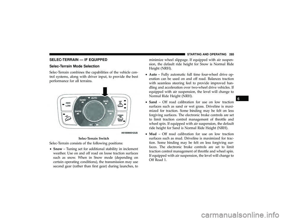
Selec-Terrain combines the capabilities of the vehicle con-
trol systems, along with driver input, to provide the best
performance for all terrains.
Selec-Terrain consists of the following positions:
•Snow – Tuning set for additional stability in inclement
weather. Use on and off road on loose traction surfaces
such as snow. When in Snow mode (depending on
certain operating conditions), the transmission may use
second gear (rather than first gear) during launches, to minimize wheel slippage. If equipped with air suspen-
sion, the default ride height for Snow is Normal Ride
Height (NRH).
• Auto – Fully automatic full time four-wheel drive op-
eration can be used on and off road. Balances traction
with seamless steering feel to provide improved han-
dling and acceleration over two-wheel drive vehicles. If
equipped with air suspension, the level will change to
Normal Ride Height (NRH).
• Sand – Off road calibration for use on low traction
surfaces such as sand or wet grass. Driveline is maxi-
mized for traction. Some binding may be felt on less
forgiving surfaces. The electronic brake controls are set
to limit traction control management of throttle and
wheel spin. If equipped with air suspension, the default
ride height for Sand is Normal Ride Height (NRH).
• Mud – Off road calibration for use on low traction
surfaces such as mud. Driveline is maximized for trac-
tion. Some binding may be felt on less forgiving sur-
faces. The electronic brake controls are set to limit
traction control management of throttle and wheel spin.
If equipped with air suspension, the level will change to
Off Road 1.
Page 288 of 626
•Rock – Off road calibration only available in 4WD Low
range. The vehicle is raised (if equipped with Air
Suspension) for improved ground clearance. Traction
based tuning with improved steer-ability for use on high
traction off-road surfaces. Use for low speed obstacles
such as large rocks, deep ruts, etc. If equipped with air
suspension, the vehicle level will change to Off-Road 2.
If the Selec-Terrain switch is in ROCK mode, and the
transfer case is switched from 4WD Low to 4WD High,
the Selec-Terrain system will return to AUTO.
NOTE: Activate the Hill Descent Control or Selec Speed
Control for steep downhill control. See “Electronic Brake
Control System” in this section for further information.
Instrument Cluster Display Messages
When the appropriate conditions exist, a message will
appear in the instrument cluster. Refer to “Instrument
Cluster Display” in “Getting To Know Your Instrument
Panel” for further information.
FUEL SAVER TECHNOLOGY 5.7L ONLY — IF
EQUIPPED
This feature offers improved fuel economy by shutting off
four of the engine’s eight cylinders during light load and
cruise conditions. The system is automatic with no driver
inputs or additional driving skills required.
NOTE: This system may take some time to return to full
functionality after a battery disconnect.
POWER STEERING
The electric power steering system will give you good
vehicle response and increased ease of maneuverability in
tight spaces. The system will vary its assist to provide light
efforts while parking and good feel while driving. If the
electric steering system experiences a fault that prevents it
from providing assist, you will still have the ability to steer
the vehicle manually.
Page 302 of 626
Metric Speed (km/h)
•Pushing the SET (-)button once will result in a 1 km/h
decrease in set speed. Each subsequent tap of the button
results in a decrease of 1 km/h.
• If the button is continually pushed, the set speed will
continue to decrease in 10 km/h decrements until the
button is released. The decrease in set speed is reflected
in the instrument cluster display.
NOTE:
• When you override and push the SET (+)button or SET
(-) buttons, the new set speed will be the current speed
of the vehicle.
• When you use the SET (-)button to decelerate, if the
engine’s braking power does not slow the vehicle suffi-
ciently to reach the set speed, the brake system will
automatically slow the vehicle. •
The ACC system applies the brake down to a full stop
when following a target vehicle. If an ACC host vehicle
follows a target vehicle to a standstill, the host vehicle
will release the vehicle brakes two seconds after coming
to a full stop.
• The ACC system maintains set speed when driving up
hill and down hill. However, a slight speed change on
moderate hills is normal. In addition, downshifting may
occur while climbing uphill or descending downhill.
This is normal operation and necessary to maintain set
speed. When driving up hill and down hill, the ACC
system will cancel if the braking temperature exceeds
normal range (overheated).
300 STARTING AND OPERATING
Page 308 of 626
NOTE:If the “ACC/FCW Unavailable Wipe Front Radar
Sensor” warning is active Normal (Fixed Speed) Cruise
Control is still available. For additional information refer to
“Normal (Fixed Speed) Cruise Control Mode” in this
section.
If weather conditions are not a factor, the driver should
examine the sensor. It may require cleaning or removal of
an obstruction. The sensor is located in the center of the
vehicle behind the lower grille.
To keep the ACC System operating properly, it is important
to note the following maintenance items:
• Always keep the sensor clean. Carefully wipe the sensor
lens with a soft cloth. Be cautious not to damage the
sensor lens.
• Do not remove any screws from the sensor. Doing so
could cause an ACC system malfunction or failure and
require a sensor realignment.
• If the sensor or front end of the vehicle is damaged due
to a collision, see your authorized dealer for service. •
Do not attach or install any accessories near the sensor,
including transparent material or aftermarket grilles.
Doing so could cause an ACC system failure or malfunc-
tion.
When the condition that deactivated the system is no
longer present, the system will return to the “Adaptive
Cruise Control Off” state and will resume function by
simply reactivating it.
NOTE:
• If the “ACC/FCW Unavailable Wipe Front Radar Sen-
sor” message occurs frequently (e.g. more than once on
every trip) without any snow, rain, mud, or other
obstruction, have the radar sensor realigned at your
authorized dealer.
• Installing a snow plow, front-end protector, an aftermar-
ket grille or modifying the grille is not recommended.
Doing so may block the sensor and inhibit ACC/FCW
operation.
306 STARTING AND OPERATING
Page 359 of 626

Changing LaneSense Status
The LaneSense system has settings to adjust the intensity of
the torque warning and the warning zone sensitivity
(early/late) that you can configure through the Uconnect
system screen. Refer to “Uconnect Settings” in “Multime-
dia” for further information.
NOTE:
•When enabled the system operates above 37 mph
(60 km/h) and below 112 mph (180 km/h).
• Use of the turn signal suppresses the warnings.
• The system will not apply torque to the steering wheel
whenever a safety system engages (anti-lock brakes,
traction control system, electronic stability control, for-
ward collision warning, etc.).
PARKVIEW REAR BACK UP CAMERA
The ParkView Rear Back Up Camera allows you to see an
on-screen image of the rear surroundings of your vehicle
whenever the gear selector is put into REVERSE. The
image will be displayed on the Navigation/Multimedia
radio display screen along with a caution note to “check
entire surroundings” across the top of the screen. After five seconds this note will disappear. The ParkView camera is
located on the rear of the vehicle above the rear license
plate.
When the vehicle is shifted out of REVERSE (with camera
delay turned off), the rear camera mode is exited and the
navigation or audio screen appears again.
Manual Activation Of The Rear View Camera
1. Press the “Controls” button located on the bottom of the
Uconnect display.
2. Press the “Backup Camera” button to turn the Rear View Camera system on.
NOTE: The ParkView Rear Back Up Camera has program-
mable modes of operation that may be selected through the
Uconnect System.
Refer to “Uconnect Settings” in “Multimedia” for further
information.
When the vehicle is shifted out of REVERSE (with camera
delay turned off), the rear camera mode is exited and the
previous screen appears again. When the vehicle is shifted
out of REVERSE (with camera delay turned on), the camera
image will continue to be displayed for up to ten seconds
after shifting out of REVERSE unless the vehicle speed
6
STARTING AND OPERATING 357