2019 JEEP GRAND CHEROKEE LIMITED wiring
[x] Cancel search: wiringPage 2 of 626

INSTALLATION OF RADIO TRANSMITTING
EQUIPMENT
Special design considerations are incorporated into this
vehicle’s electronic system to provide immunity to radio
frequency signals. Mobile two-way radios and telephone
equipment must be installed properly by trained person-
nel. The following must be observed during installation.
The positive power connection should be made directly
to the battery and fused as close to the battery as possible.
The negative power connection should be made to body
sheet metal adjacent to the negative battery connection.
This connection should not be fused.
Antennas for two-way radios should be mounted on the
roof or the rear area of the vehicle. Care should be used
in mounting antennas with magnet bases. Magnets may
affect the accuracy or operation of the compass on
vehicles so equipped.
The antenna cable should be as short as practical and
routed away from the vehicle wiring when possible. Use
only fully shielded coaxial cable.
Carefully match the antenna and cable to the radio to
ensure a low Standing Wave Ratio (SWR).Mobile radio equipment with output power greater than
normal may require special precautions.
All installations should be checked for possible interfer-
ence between the communications equipment and the
vehicle’s electronic systems.
WARNING:
Operating, servicing and maintaining a
passenger vehicle or off-road highway
motor vehicle can expose you to chemicals
including engine exhaust, carbon monoxide,
phthalates, and lead, which are known to
the State of California to cause cancer and
birth defects or other reproductive harm.
To minimize exposure, avoid breathing
exhaust, do not idle the engine except as
necessary, service your vehicle in a
well-ventilated area and wear gloves or
wash your hands frequently when servicing
your vehicle. For more information go to
www.P65Warnings.ca.gov/passenger-vehicle.
VEHICLES SOLD IN CANADA
With respect to any Vehicles Sold in Canada, the name
FCA US LLC shall be deemed to be deleted and the name
FCA Canada Inc. used in substitution therefore.
DRIVING AND ALCOHOL
Drunken driving is one of the most frequent causes of
accidents.
Your driving ability can be seriously impaired with blood
alcohol levels far below the legal minimum. If you are
drinking, don’t drive. Ride with a designated non-
drinking driver, call a cab, a friend, or use public trans-
portation.
WARNING!
Driving after drinking can lead to an accident.
Your perceptions are less sharp, your reflexes are
slower, and your judgment is impaired when you
have been drinking. Never drink and then drive.
This manual illustrates and describes the operation of
features and equipment that are either standard or op-
tional on this vehicle. This manual may also include a
description of features and equipment that are no longer
available or were not ordered on this vehicle. Please
disregard any features and equipment described in this
manual that are not on this vehicle.
FCA US LLC reserves the right to make changes in design
and specifications, and/or make additions to or improve-
ments to its products without imposing any obligation
upon itself to install them on products previously manu-
factured.
Copyright © 2018 FCA US LLC
Page 214 of 626
WARNING!
Deployed AHRs are not able to best protect you in all
types of collisions. Have deployed AHRs reset by an
authorized dealer immediately.
Supplemental Restraint Systems (SRS)
Some of the safety features described in this section may be
standard equipment on some models, or may be optional
equipment on others. If you are not sure, ask an authorized
dealer.
The air bag system must be ready to protect you in a
collision. The Occupant Restraint Controller (ORC) moni-
tors the internal circuits and interconnecting wiring asso-
ciated with the electrical Air Bag System Components.
Your vehicle may be equipped with the following Air Bag
System Components:
Air Bag System Components
•Occupant Restraint Controller (ORC)
• Air Bag Warning Light
Page 223 of 626
The Side Air Bags will not deploy in all rollover events. The
rollover sensing system determines if a rollover event may
be in progress and whether deployment is appropriate. In
the event the vehicle experiences a rollover or near rollover
event, and deployment of the Side Air Bags is appropriate,
the rollover sensing system will also deploy the seat belt
pretensioners on both sides of the vehicle.
The SABICs may help reduce the risk of partial or complete
ejection of vehicle occupants through side windows in
certain rollover or side impact events.
Air Bag System Components
NOTE:The Occupant Restraint Controller (ORC) monitors
the internal circuits and interconnecting wiring associated
with electrical Air Bag System Components listed below:
• Occupant Restraint Controller (ORC)
• Air Bag Warning Light
Page 226 of 626
Maintaining Your Air Bag System
WARNING!
•Modifications to any part of the air bag system could
cause it to fail when you need it. You could be
injured if the air bag system is not there to protect
you. Do not modify the components or wiring, in-
cluding adding any kind of badges or stickers to the
steering wheel hub trim cover or the upper passenger
side of the instrument panel. Do not modify the front
bumper, vehicle body structure, or add aftermarket
side steps or running boards.
• It is dangerous to try to repair any part of the air bag
system yourself. Be sure to tell anyone who works on
your vehicle that it has an air bag system.
• Do not attempt to modify any part of your air bag
system. The air bag may inflate accidentally or may
not function properly if modifications are made.
Take your vehicle to an authorized dealer for any air
bag system service. If your seat, including your trim
cover and cushion, needs to be serviced in any way
(including removal or loosening/tightening of seat
attachment bolts), take the vehicle to an authorized
(Continued)
Page 375 of 626
Towing Requirements — Trailer Lights And Wiring
Whenever you pull a trailer, regardless of the trailer size,
stoplights and turn signals on the trailer are required for
motoring safety.
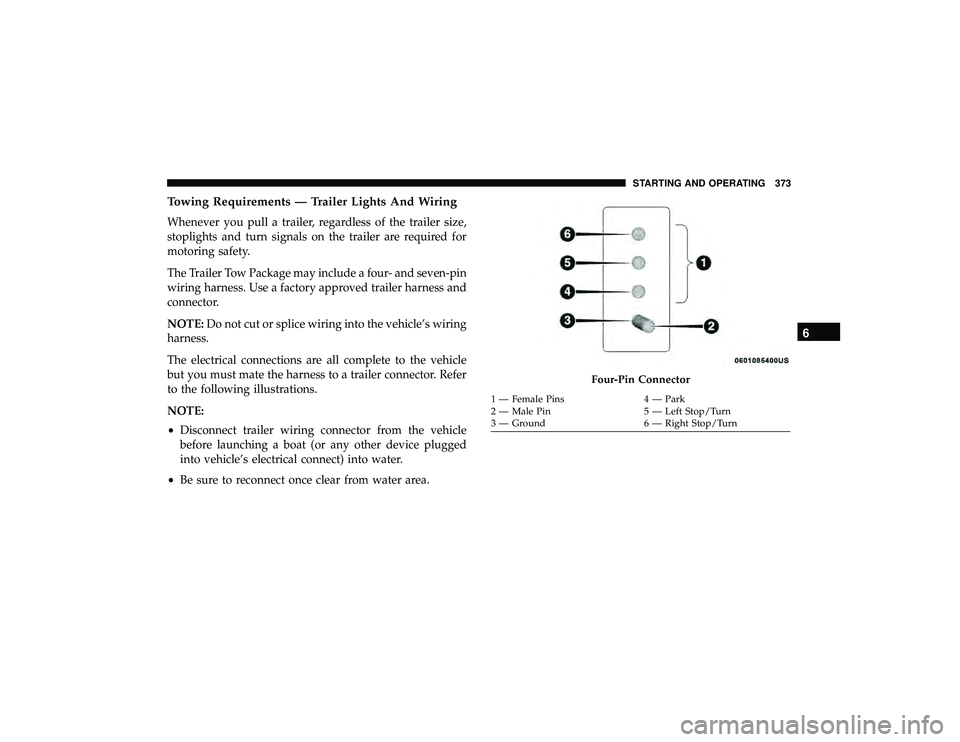
The Trailer Tow Package may include a four- and seven-pin
wiring harness. Use a factory approved trailer harness and
connector.
NOTE:Do not cut or splice wiring into the vehicle’s wiring
harness.
The electrical connections are all complete to the vehicle
but you must mate the harness to a trailer connector. Refer
to the following illustrations.
NOTE:
• Disconnect trailer wiring connector from the vehicle
before launching a boat (or any other device plugged
into vehicle’s electrical connect) into water.
• Be sure to reconnect once clear from water area.
Page 386 of 626
![JEEP GRAND CHEROKEE LIMITED 2019 Owners Manual Radar Sensor Removal Procedure (If Equipped With
Adaptive Cruise Control [ACC]):
1. With the lower fascia removed, which provides access tothe sensor and bracket, disconnect the wiring harness
from th JEEP GRAND CHEROKEE LIMITED 2019 Owners Manual Radar Sensor Removal Procedure (If Equipped With
Adaptive Cruise Control [ACC]):
1. With the lower fascia removed, which provides access tothe sensor and bracket, disconnect the wiring harness
from th](/manual-img/16/56024/w960_56024-385.png)
Radar Sensor Removal Procedure (If Equipped With
Adaptive Cruise Control [ACC]):
1. With the lower fascia removed, which provides access tothe sensor and bracket, disconnect the wiring harness
from the sensor.
2. Using a suitable tool, disconnect the wire clip from the bracket.
3. Using a suitable tool, remove the two fasteners that hold the sensor bracket to the bumper beam.
NOTE: It is recommended to scribe location to assist in
reinstallation.
4. Locate the protective connector on the rear of the bumper beam.
NOTE:Only models with the Off Road Package are
equipped with the a protective connector.
5. Remove the plug from the protective connector and install on the sensor.
6. Insert the wiring harness connector into the protective connector.
Page 387 of 626
7. Store sensor and bracket in a safe place.
NOTE:All cruise control functions will be disabled when
the radar sensor is disconnected.
Radar Sensor Installation Procedure (If Equipped With
Adaptive Cruise Control [ACC]):
1. Disconnect the wiring harness connector from the pro- tective connector on the bumper beam.
2. Remove plug from radar sensor and install in protective connector.
3. Using the previously scribed marks, reinstall the radar sensor and bracket using the two fasteners.
NOTE: Some alignment may be required upon fascia
installation to align sensor with fascia.
4. Install the wiring harness connector into the radar sensor.
NOTE: If you receive a fault, see your authorized dealer
they may need to perform a sensor alignment.
Lower Front Fascia Installation
NOTE: This will only work if you have a helper. 1. Starting at the center of the vehicle, engage a sufficient
number of tabs to support the weight of the lower fascia
(typically one or two tabs) into the upper fascia.
2. Working your way outward, engage the tabs into the slots on one side of the vehicle.
3. Return to the center of the vehicle and repeat Step 2 to the opposite side of the vehicle.
NOTE: •It may be necessary to apply additional force to
individual tabs to make sure they are fully engaged.
• Do not use any tools to apply additional force to the
tabs as damage to the upper and lower fascias may
result.
4. Reinstall the seven quarter turn fasteners.
Quadra-Lift — If Equipped
When off-roading, it is recommended that the lowest
useable vehicle height that will clear the current obstacle or
terrain be selected. The vehicle height should then be
raised as required by the changes in terrain.
6
STARTING AND OPERATING 385
Page 623 of 626
Jacking........................... .413, 470
Life Of Tires ........................... .482
Load Capacity .......................... .476
Pressure Monitoring System (TPMS) ........156, 192
Quality Grading ........................ .490
Radial ............................... .480
Replacement ........................ .421, 482
Rotation .............................. .489
Safety ............................ .471, 477
Sizes ................................ .472
Snow Tires ............................ .484
Spare Tires .................. .414, 485, 486, 487
Spinning .............................. .481
Trailer Towing .......................... .371
Tread Wear Indicators .....................481
Wheel Mounting ........................ .421
Wheel Nut Torque ....................... .499
Tire Safety Information .......................471
Tongue Weight/Trailer Weight .................369
To Open Hood ........................... .106
Tow Hooks Emergency ............................ .432
Towing ............................. .364, 430
Disabled Vehicle ........................ .430
Guide ................................ .367Recreational
........................... .376
Weight ............................... .367
Towing Behind A Motorhome ..................376
Traction Control .......................... .171
Trailer Sway Control (TSC) ....................174
Trailer Towing ............................ .364
Cooling System Tips ..................... .375
Hitches ............................... .366
Minimum Requirements ................... .370
Tips ................................. .374
T railer
And Tongue Weight ..................369
Wiring ............................... .373
Trailer Towing Guide ....................... .367
Trailer Weight ............................ .367
Transfer Case ............................ .470
Fluid ................................ .508
Maintenance ........................... .470
Transmission ............................. .264
Automatic ......................... .264, 468
Fluid ................................ .508
Maintenance ........................... .468
Shifting .............................. .262
Transmitter, Garage Door Opener (Homelink) .......114
Transporting Pets ......................... .244
Tread Wear Indicators .......................481
12
INDEX 621