Page 126 of 626
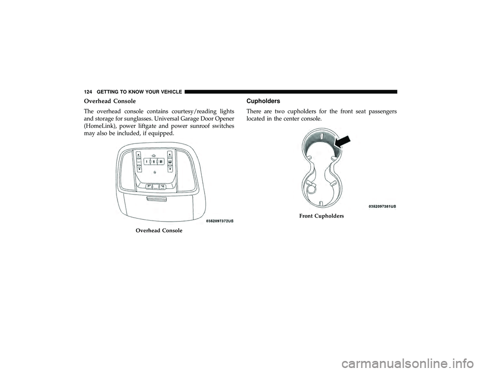
Overhead Console
The overhead console contains courtesy/reading lights
and storage for sunglasses. Universal Garage Door Opener
(HomeLink), power liftgate and power sunroof switches
may also be included, if equipped.
Cupholders
There are two cupholders for the front seat passengers
located in the center console.
Front Cupholders
124 GETTING TO KNOW YOUR VEHICLE
Page 131 of 626
WARNING!(Continued)
•Close the lid when not in use and while driving the
vehicle.
• If this outlet is mishandled, it may cause an electric
shock and failure.
CAUTION!
•Many accessories that can be plugged in draw power
from the vehicle’s battery, even when not in use (i.e.,
cellular phones, etc.). Eventually, if plugged in long
enough, the vehicle’s battery will discharge suffi-
ciently to degrade battery life and/or prevent the
engine from starting.
• Accessories that draw higher power (i.e., coolers,
vacuum cleaners, lights, etc.) will degrade the battery
even more quickly. Only use these intermittently and
with greater caution.
• After the use of high power draw accessories, or long
periods of the vehicle not being started (with acces-
sories still plugged in), the vehicle must be driven a
sufficient length of time to allow the generator to
recharge the vehicle’s battery.
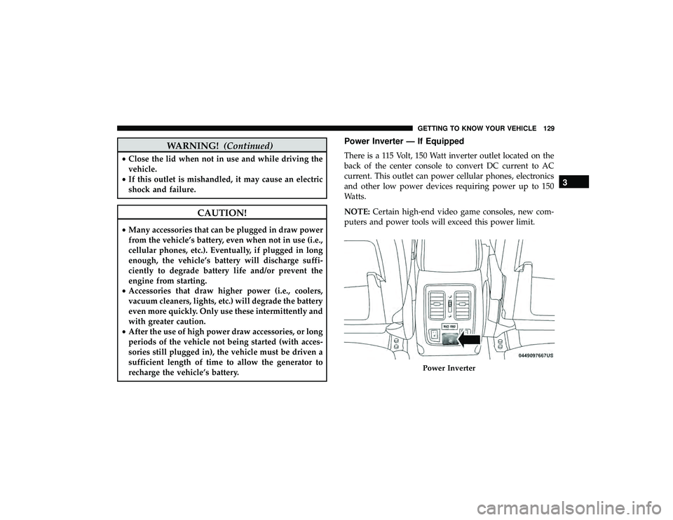
Power Inverter — If Equipped
There is a 115 Volt, 150 Watt inverter outlet located on the
back of the center console to convert DC current to AC
current. This outlet can power cellular phones, electronics
and other low power devices requiring power up to 150
Watts.
NOTE: Certain high-end video game consoles, new com-
puters and power tools will exceed this power limit.
Page 141 of 626

Secondary Method For Oil Change Reset Procedure
1. Without pushing the brake pedal, place the ignition inthe ON/RUN position (do not start the engine).
2. Fully press the accelerator pedal, slowly, three times within ten seconds.
3. Without pushing the brake pedal, place the ignition in the OFF/LOCK position.
NOTE: If the indicator message illuminates when you
start the vehicle, the oil change indicator system did not
reset. If necessary, repeat this procedure.
Instrument Cluster Display Messages
Includes the following, but not limited to:
• Front Seatbelts Unbuckled
• Driver Seat Belt Unbuckled
• Passenger Seat Belt Unbuckled
• Traction Control Off
• Washer Fluid Low
• Oil Pressure Low
• Oil Change Due •
Fuel Low
• Service Anti-lock Brake System
• Service Electronic Throttle Control
• Service Power Steering
• Cruise Control Off
• Cruise Control Ready
• ACC Driver Override
• Cruise Control Set To XXX MPH
• Tire Pressure Screen With Low Tire(s) “Inflate Tire to
XX”
• Service Tire Pressure System
• Speed Warning Set To XXX MPH
• Speed Warning Exceeded
• Parking Brake Engaged
• Brake Fluid Low
• Service Electronic Braking System
• Engine Temperature Hot
• Lights On
4
GETTING TO KNOW YOUR INSTRUMENT PANEL 139
Page 143 of 626
•Vehicle Cannot Be Lowered Door Open
• Air Suspension Temporarily Disabled
• Battery Low Start Engine To Change Ride Height
For further information on the color warning and indicator
lights in the instrument cluster, refer to “Warning Lights
And Messages” in “Getting To Know Your Instrument
Panel”.
Instrument Cluster Display Menu Items
The instrument cluster display can be used to view the
main menu items for several features. Use the upand
down arrow buttons to scroll through the driver interactive
display menu options until the desired menu is reached.
NOTE: Depending on the vehicle’s options, feature set-
tings may vary.
Speedometer
Push and release the upordown arrow button until the
main gauge menu icon is displayed in the instrument
cluster display. Push and release the leftorright arrow
button to select the analog or digital type speedometer
display. Push and release the OKbutton to toggle units
(mph or km/h) of the speedometer.
Accessibility — If Equipped
Accessibility is a feature of the DVD/Blu-ray system that
announces a function prior to performing the action. For
further information refer to “Uconnect Settings” in “Mul-
timedia.”
Vehicle Info
Push and release the upordown arrow button until the
Vehicle Info menu icon is displayed in the instrument
cluster display. Push and release the leftorright arrow
button to scroll through the information submenus and
push and release the OKbutton to select or reset the
resettable submenus.
Page 148 of 626

•Trip Info (show/hide)
• Stop/Start
• Audio (show/hide)
• Messages
• Screen Setup
The menu with (show/hide) means user can press OK
button to choose show or hide this menu on the instrument
cluster display.
Battery Saver On/Battery Saver Mode Message —
Electrical Load Reduction Actions (If Equipped)
This vehicle is equipped with an Intelligent Battery Sensor
(IBS) to perform additional monitoring of the electrical
system and status of the vehicle battery.
In cases when the IBS detects charging system failure, or
the vehicle battery conditions are deteriorating, electrical
load reduction actions will take place to extend the driving
time and distance of the vehicle. This is done by reducing
power to or turning off non-essential electrical loads. Load reduction is only active when the engine is running.
It will display a message if there is a risk of battery
depletion to the point where the vehicle may stall due to
lack of electrical supply, or will not restart after the current
drive cycle.
When load reduction is activated, the message “Battery
Saver On” or “Battery Saver Mode” will appear in the
instrument cluster display.
These messages indicate the vehicle battery has a low state
of charge and continues to lose electrical charge at a rate
that the charging system cannot sustain.
NOTE:
•
The charging system is independent from load reduc-
tion. The charging system performs a diagnostic on the
charging system continuously.
• If the Battery Charge Warning Light is on it may indicate
a problem with the charging system. Refer to “Battery
Charge Warning Light” in “Warning Lights And Mes-
sages” located in ”Getting To Know Your Instrument
Panel” for further information.
146 GETTING TO KNOW YOUR INSTRUMENT PANEL
Page 149 of 626

The electrical loads that may be switched off (if equipped),
and vehicle functions which can be effected by load
reduction:
•Heated Seat/Vented Seats/Heated Wheel
• Rear Defroster And Heated Mirrors
• HVAC System
• 150W Power Inverter System
• Audio and Telematics System
Loss of the battery charge may indicate one or more of the
following conditions:
• The charging system cannot deliver enough electrical
power to the vehicle system because the electrical loads
are larger than the capability of charging system. The
charging system is still functioning properly.
• Turning on all possible vehicle electrical loads (e.g.
HVAC to max settings, exterior and interior lights,
overloaded power outlets +12V, 150W, USB ports) dur-
ing certain driving conditions (city driving, towing,
frequent stopping).
• Installing options like additional lights, upfitter electri-
cal accessories, audio systems, alarms and similar de-
vices. •
Unusual driving cycles (short trips separated by long
parking periods).
• The vehicle was parked for an extended period of time
(weeks, months).
• The battery was recently replaced and was not charged
completely.
• The battery was discharged by an electrical load left on
when the vehicle was parked.
• The battery was used for an extended period with the
engine not running to supply radio, lights, chargers,
+12V portable appliances like vacuum cleaner ’s, game
consoles and similar devices.
What to do when an electrical load reduction action
message is present (“Battery Saver On” or “Battery Saver
Mode”)
During a trip:
• Reduce power to unnecessary loads if possible:
– Turn off redundant lights (interior or exterior)
– Check what may be plugged in to power outlets +12V, 150W, USB ports
– Check HVAC settings (blower, temperature)
– Check the audio settings (volume)
4
GETTING TO KNOW YOUR INSTRUMENT PANEL 147
Page 150 of 626
After a trip:
•Check if any aftermarket equipment was installed (ad-
ditional lights, upfitter electrical accessories, audio sys-
tems, alarms) and review specifications if any (load and
Ignition Off Draw currents).
• Evaluate the latest driving cycles (distance, driving time
and parking time).
• The vehicle should have service performed if the mes-
sage is still present during consecutive trips and the
evaluation of the vehicle and driving pattern did not
help to identify the cause.
TRIP COMPUTER
Push and release the up or down arrow button until the
Trip A or Trip B icon is highlighted in the instrument
cluster display (Toggle left or right to select Trip A or Trip
B). Push and release the OK button to display the Trip
information. Trip A
•
Shows the total distance traveled for Trip A since the last
reset.
• Shows the elapsed time traveled for Trip A since the last
reset.
Trip B
• Shows the total distance traveled for Trip B since the last
reset.
• Shows the elapsed time traveled for Trip B since the last
reset.
Elapsed Time
Shows the total elapsed time of travel since the last reset
when the ignition switch is in the ACC position. Elapsed
time will increment when the ignition switch is in the ON
or START position.
To Reset A Trip Function
Reset will only occur while a resettable function is selected
(highlighted). Push and hold the OKbutton to clear the
resettable function being displayed.
148 GETTING TO KNOW YOUR INSTRUMENT PANEL
Page 151 of 626
WARNING LIGHTS AND MESSAGES
The warning/indicator lights will illuminate in the instru-
ment panel together with a dedicated message and/or
acoustic signal when applicable. These indications are
indicative and precautionary and as such must not be
considered as exhaustive. Always refer to the information
in this chapter in the event of a failure indication. All active
telltales will display first if applicable. The system check
menu may appear different based upon equipment options
and current vehicle status. Some telltales are optional and
may not appear.
Red Warning Lights