Page 375 of 626
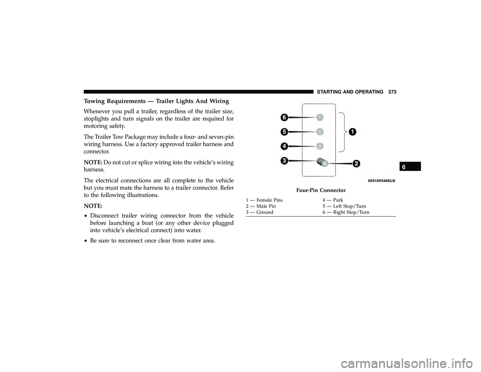
Towing Requirements — Trailer Lights And Wiring
Whenever you pull a trailer, regardless of the trailer size,
stoplights and turn signals on the trailer are required for
motoring safety.
The Trailer Tow Package may include a four- and seven-pin
wiring harness. Use a factory approved trailer harness and
connector.
NOTE:Do not cut or splice wiring into the vehicle’s wiring
harness.
The electrical connections are all complete to the vehicle
but you must mate the harness to a trailer connector. Refer
to the following illustrations.
NOTE:
• Disconnect trailer wiring connector from the vehicle
before launching a boat (or any other device plugged
into vehicle’s electrical connect) into water.
• Be sure to reconnect once clear from water area.
Page 382 of 626
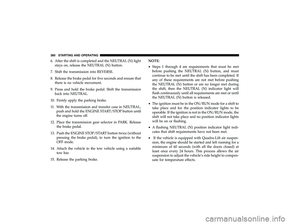
6. After the shift is completed and the NEUTRAL (N) lightstays on, release the NEUTRAL (N) button.
7. Shift the transmission into REVERSE.
8. Release the brake pedal for five seconds and ensure that there is no vehicle movement.
9. Press and hold the brake pedal. Shift the transmission back into NEUTRAL.
10. Firmly apply the parking brake.
11. With the transmission and transfer case in NEUTRAL, push and hold the ENGINE START/STOP button until
the engine turns off.
12. Place the transmission gear selector in PARK. Release the brake pedal.
13. Push the ENGINE STOP/START button twice (without pressing the brake pedal), to turn the ignition to the
OFF mode.
14. Attach the vehicle to the tow vehicle using a suitable tow bar.
15. Release the parking brake. NOTE:
•
Steps 1 through 4 are requirements that must be met
before pushing the NEUTRAL (N) button, and must
continue to be met until the shift has been completed. If
any of these requirements are not met before pushing
the NEUTRAL (N) button or are no longer met during
the shift, then the NEUTRAL (N) indicator light will
flash continuously until all requirements are met or until
the NEUTRAL (N) button is released.
• The ignition must be in the ON/RUN mode for a shift to
take place and for the position indicator lights to be
operable. If the ignition is not in the ON/RUN mode, the
shift will not take place and no position indicator lights
will be on or flashing.
• A flashing NEUTRAL (N) position indicator light indi-
cates that shift requirements have not been met.
• If the vehicle is equipped with Quadra-Lift air suspen-
sion, the engine should be started and left running for a
minimum of 60 seconds (with all the doors closed) at
least once every 24 hours. This process allows the air
suspension to adjust the vehicle’s ride height to compen-
sate for temperature effects.
380 STARTING AND OPERATING
Page 384 of 626
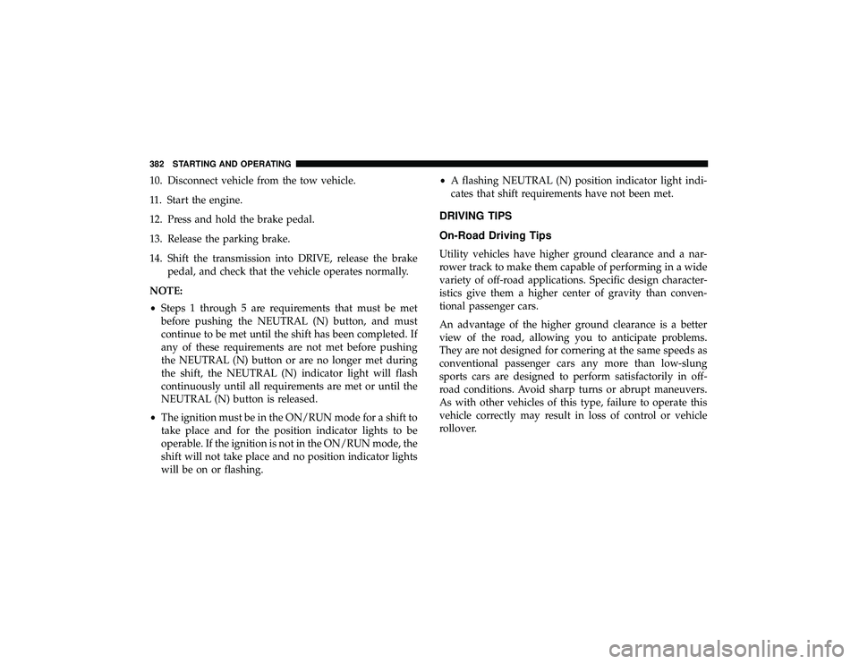
10. Disconnect vehicle from the tow vehicle.
11. Start the engine.
12. Press and hold the brake pedal.
13. Release the parking brake.
14. Shift the transmission into DRIVE, release the brakepedal, and check that the vehicle operates normally.
NOTE:
• Steps 1 through 5 are requirements that must be met
before pushing the NEUTRAL (N) button, and must
continue to be met until the shift has been completed. If
any of these requirements are not met before pushing
the NEUTRAL (N) button or are no longer met during
the shift, the NEUTRAL (N) indicator light will flash
continuously until all requirements are met or until the
NEUTRAL (N) button is released.
• The ignition must be in the ON/RUN mode for a shift to
take place and for the position indicator lights to be
operable. If the ignition is not in the ON/RUN mode, the
shift will not take place and no position indicator lights
will be on or flashing. •
A flashing NEUTRAL (N) position indicator light indi-
cates that shift requirements have not been met.
DRIVING TIPS
On-Road Driving Tips
Utility vehicles have higher ground clearance and a nar-
rower track to make them capable of performing in a wide
variety of off-road applications. Specific design character-
istics give them a higher center of gravity than conven-
tional passenger cars.
An advantage of the higher ground clearance is a better
view of the road, allowing you to anticipate problems.
They are not designed for cornering at the same speeds as
conventional passenger cars any more than low-slung
sports cars are designed to perform satisfactorily in off-
road conditions. Avoid sharp turns or abrupt maneuvers.
As with other vehicles of this type, failure to operate this
vehicle correctly may result in loss of control or vehicle
rollover.
382 STARTING AND OPERATING
Page 406 of 626
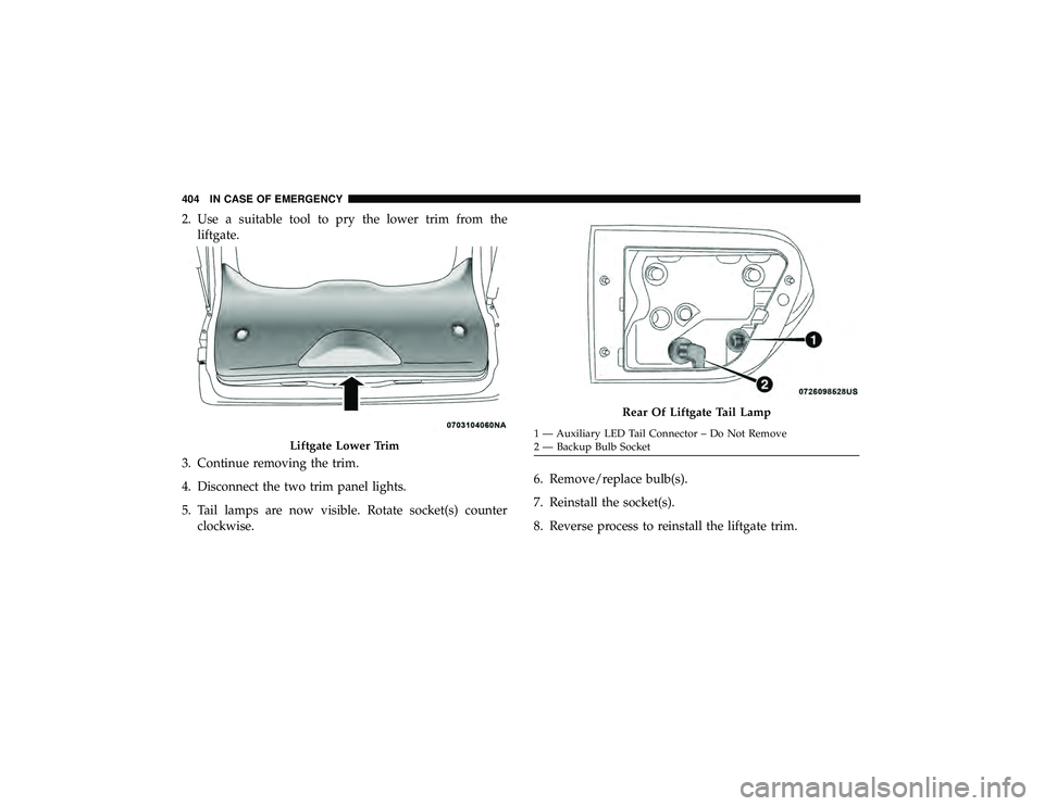
2. Use a suitable tool to pry the lower trim from theliftgate.
3. Continue removing the trim.
4. Disconnect the two trim panel lights.
5. Tail lamps are now visible. Rotate socket(s) counter clockwise. 6. Remove/replace bulb(s).
7. Reinstall the socket(s).
8. Reverse process to reinstall the liftgate trim.
Rear Of Liftgate Tail Lamp
Page 410 of 626
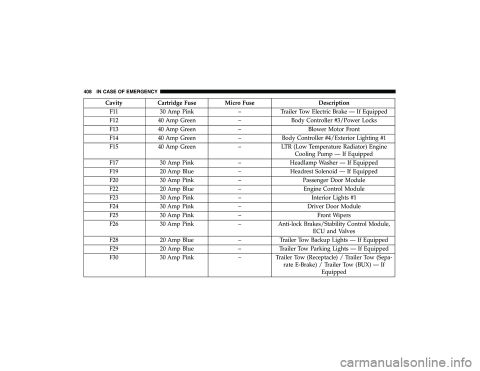
CavityCartridge Fuse Micro Fuse Description
F11 30 Amp Pink –Trailer Tow Electric Brake — If Equipped
F12 40 Amp Green –Body Controller #3/Power Locks
F13 40 Amp Green –Blower Motor Front
F14 40 Amp Green –Body Controller #4/Exterior Lighting #1
F15 40 Amp Green –LTR (Low Temperature Radiator) Engine
Cooling Pump — If Equipped
F17 30 Amp Pink –Headlamp Washer — If Equipped
F19 20 Amp Blue –Headrest Solenoid — If Equipped
F20 30 Amp Pink –Passenger Door Module
F22 20 Amp Blue –Engine Control Module
F23 30 Amp Pink –Interior Lights #1
F24 30 Amp Pink –Driver Door Module
F25 30 Amp Pink – Front Wipers
F26 30 Amp Pink –Anti-lock Brakes/Stability Control Module,
ECU and Valves
F28 20 Amp Blue –Trailer Tow Backup Lights — If Equipped
F29 20 Amp Blue –Trailer Tow Parking Lights — If Equipped
F30 30 Amp Pink –Trailer Tow (Receptacle) / Trailer Tow (Sepa-
rate E-Brake) / Trailer Tow (BUX) — If Equipped
408 IN CASE OF EMERGENCY
Page 411 of 626
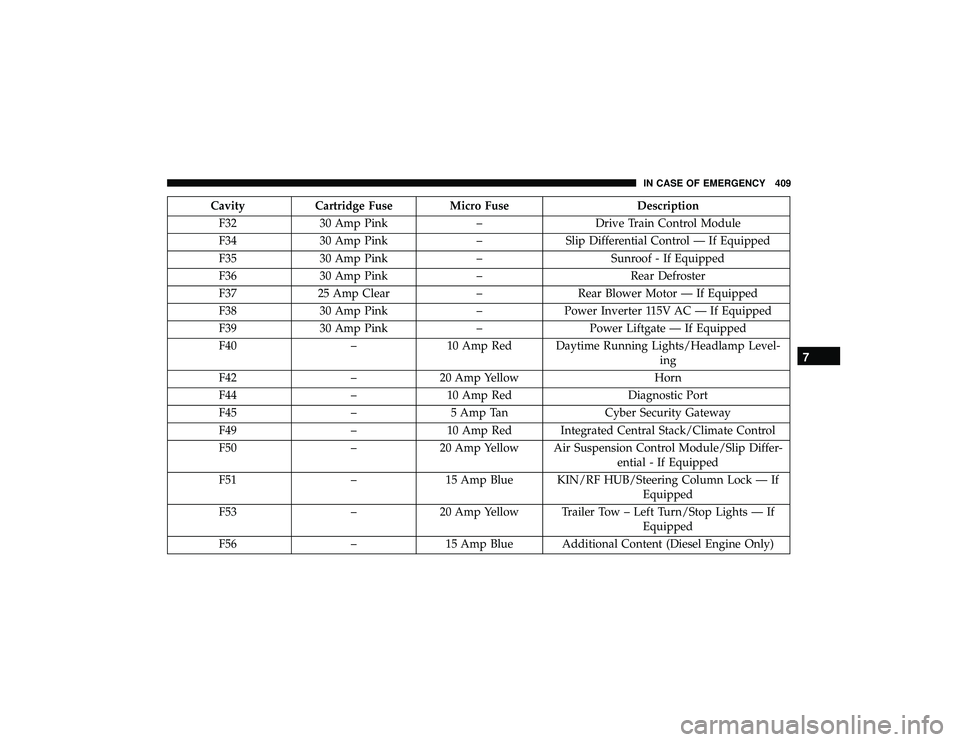
CavityCartridge Fuse Micro Fuse Description
F32 30 Amp Pink –Drive Train Control Module
F34 30 Amp Pink –Slip Differential Control — If Equipped
F35 30 Amp Pink –Sunroof - If Equipped
F36 30 Amp Pink –Rear Defroster
F37 25 Amp Clear –Rear Blower Motor — If Equipped
F38 30 Amp Pink –Power Inverter 115V AC — If Equipped
F39 30 Amp Pink –Power Liftgate — If Equipped
F40 –10 Amp Red Daytime Running Lights/Headlamp Level-
ing
F42 –20 Amp Yellow Horn
F44 –10 Amp Red Diagnostic Port
F45 –5 Amp Tan Cyber Security Gateway
F49 –10 Amp Red Integrated Central Stack/Climate Control
F50 –20 Amp Yellow Air Suspension Control Module/Slip Differ-
ential - If Equipped
F51 –15 Amp Blue KIN/RF HUB/Steering Column Lock — If
Equipped
F53 –20 Amp Yellow Trailer Tow – Left Turn/Stop Lights — If
Equipped
F56 –15 Amp Blue Additional Content (Diesel Engine Only)
7
IN CASE OF EMERGENCY 409
Page 413 of 626
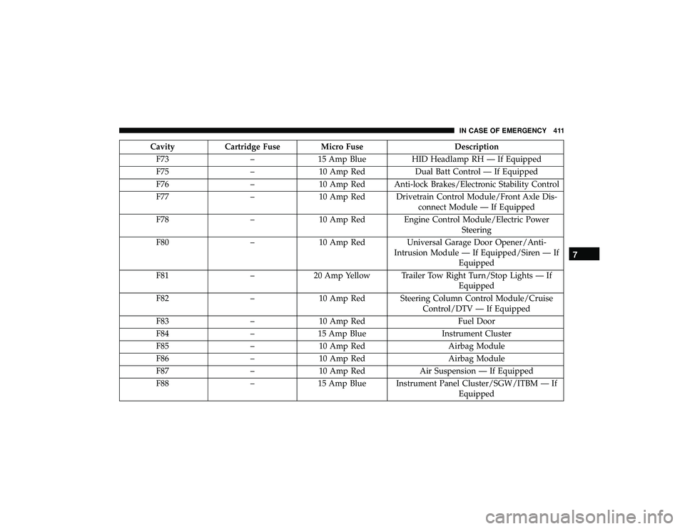
CavityCartridge Fuse Micro Fuse Description
F73 –15 Amp Blue HID Headlamp RH — If Equipped
F75 –10 Amp Red Dual Batt Control — If Equipped
F76 –10 Amp Red Anti-lock Brakes/Electronic Stability Control
F77 –10 Amp Red Drivetrain Control Module/Front Axle Dis-
connect Module — If Equipped
F78 –10 Amp Red Engine Control Module/Electric Power
Steering
F80 –10 Amp Red Universal Garage Door Opener/Anti-
Intrusion Module — If Equipped/Siren — If Equipped
F81 –20 Amp Yellow Trailer Tow Right Turn/Stop Lights — If
Equipped
F82 –10 Amp Red Steering Column Control Module/Cruise
Control/DTV — If Equipped
F83 –10 Amp Red Fuel Door
F84 –15 Amp Blue Instrument Cluster
F85 –10 Amp Red Airbag Module
F86 –10 Amp Red Airbag Module
F87 –10 Amp Red Air Suspension — If Equipped
F88 –15 Amp Blue Instrument Panel Cluster/SGW/ITBM — If
Equipped
7
IN CASE OF EMERGENCY 411
Page 439 of 626

SCHEDULED SERVICING
Scheduled Servicing — Gasoline Engine
Your vehicle is equipped with an automatic oil change
indicator system. The oil change indicator system will
remind you that it is time to take your vehicle in for
scheduled maintenance.
Based on engine operation conditions, the oil change
indicator message will illuminate. This means that service
is required for your vehicle. Operating conditions such as
frequent short-trips, trailer tow, extremely hot or cold
ambient temperatures, and E85 fuel usage will influence
when the “Oil Change Required” message is displayed.
Severe operating conditions can cause the change oil
message to illuminate as early as 3,500 miles (5,600 km)
since last reset. Have your vehicle serviced as soon as
possible, within the next 500 miles (805 km).
Your authorized dealer will reset the oil change indicator
message after completing the scheduled oil change.
NOTE:Under no circumstances should oil change inter-
vals exceed 10,000 miles (16,000 km), twelve months or 350
hours of engine run time, whichever comes first. The 350
hours of engine run or idle time is generally only a concern
for fleet customers. Severe Duty All Models
Change Engine Oil at 4,000 miles (6,500 km) or 350 hours of
engine run time if the vehicle is operated in a dusty and
off-road environment, or is operated predominantly at idle
or only very low engine RPM’s. This type of vehicle use is
considered Severe Duty.
Once A Month Or Before A Long Trip:
•
Check engine oil level.
• Check windshield washer fluid level.
• Check the tire inflation pressures and look for unusual
wear or damage.
• Check the fluid levels of the coolant reservoir, brake
master cylinder and fill as needed.
• Check function of all interior and exterior lights
Maintenance Plan
Required Maintenance
Refer to the Maintenance Plans on the following pages for
required maintenance.
8
SERVICING AND MAINTENANCE 437