2019 INFINITI QX50 warning
[x] Cancel search: warningPage 108 of 288

7. Monitor system
the object projects over the actual backing
up course.
ADJUSTING THE SCREEN
The RearView Monitor settings can be
changed with the following procedure.
1. Push
Page 110 of 288

7. Monitor system
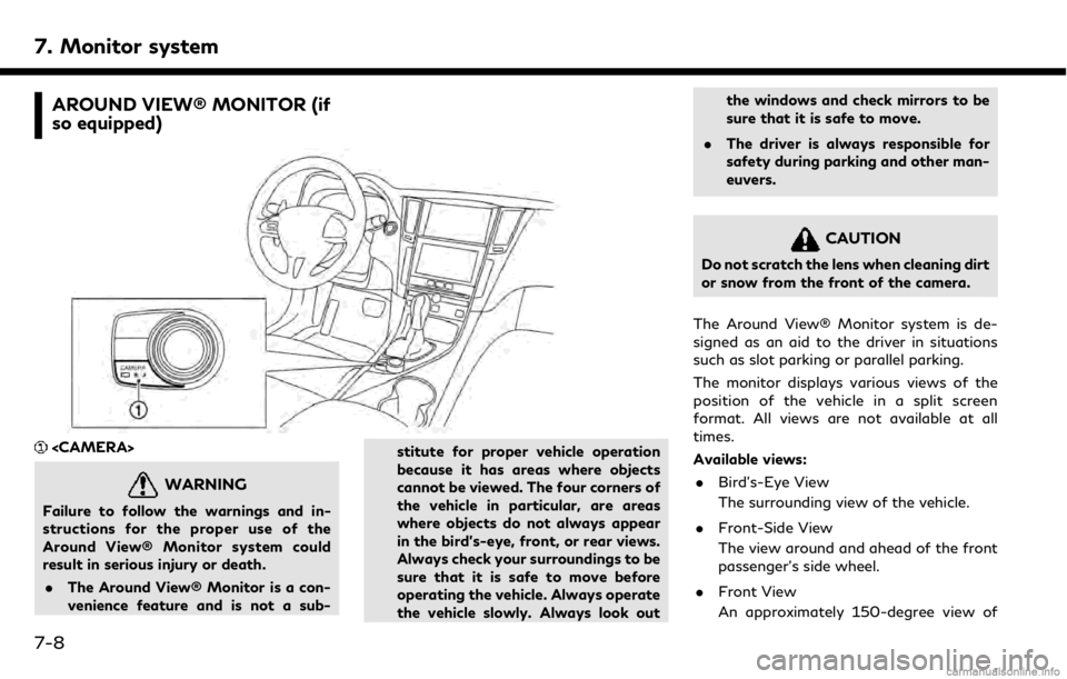
AROUND VIEW® MONITOR (if
so equipped)
WARNING
Failure to follow the warnings and in-
structions for the proper use of the
Around View® Monitor system could
result in serious injury or death.. The Around View® Monitor is a con-
venience feature and is not a sub- stitute for proper vehicle operation
because it has areas where objects
cannot be viewed. The four corners of
the vehicle in particular, are areas
where objects do not always appear
in the bird’s-eye, front, or rear views.
Always check your surroundings to be
sure that it is safe to move before
operating the vehicle. Always operate
the vehicle slowly. Always look outthe windows and check mirrors to be
sure that it is safe to move.
. The driver is always responsible for
safety during parking and other man-
euvers.
CAUTION
Do not scratch the lens when cleaning dirt
or snow from the front of the camera.
The Around View® Monitor system is de-
signed as an aid to the driver in situations
such as slot parking or parallel parking.
The monitor displays various views of the
position of the vehicle in a split screen
format. All views are not available at all
times.
Available views: . Bird’s-Eye View
The surrounding view of the vehicle.
. Front-Side View
The view around and ahead of the front
passenger’s side wheel.
. Front View
An approximately 150-degree view of
7-8
Page 111 of 288

the front of the vehicle.
. Front-Wide View
An approximately 180-degree view of
the front of the vehicle.
. Rear View
An approximately 150-degree view of
the rear of the vehicle.
. Rear-Wide View (if so equipped)
An approximately 180-degree view of
the rear of the vehicle.
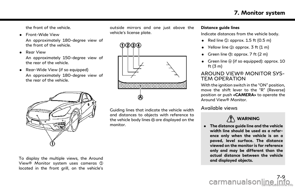
To display the multiple views, the Around
View® Monitor system uses cameras
located in the front grill, on the vehicle’s outside mirrors and one just above the
vehicle’s license plate.
Guiding lines that indicate the vehicle width
and distances to objects with reference to
the vehicle body lines
are displayed on the
monitor. Distance guide lines
Indicate distances from the vehicle body.
. Red line
: approx. 1.5 ft (0.5 m)
. Yellow line
: approx. 3 ft (1 m)
. Green line
: approx. 7 ft (2 m)
. Green line
(if so equipped): approx. 10
ft (3 m)
AROUND VIEW® MONITOR SYS-
TEM OPERATION
With the ignition switch in the “ON” position,
move the shift lever to the “R” (Reverse)
position or push
Around View® Monitor.
Available views
WARNING
. The distance guide line and the vehicle
width line should be used as a refer-
ence only when the vehicle is on a
paved, level surface. The distance
viewed on the monitor is for reference
only and may be different than the
actual distance between the vehicle
and displayed objects.
7. Monitor system
7-9
Page 114 of 288

7. Monitor system
the first time after the ignition switch is
placed in the “ON” position.
The driver can check the approximate direc-
tion and angle of the tire on the display by
tire icon
when driving the vehicle forward
or backward.
Predictive course lines (
and) indicate
the predictive course when operating the
vehicle. The predictive course lines will be
displayed on the monitor when the steering
wheel is turned. The predictive course lines
will move depending on how much the
steering wheel is turned and will not be
displayed while the steering wheel is in the
neutral position.
WARNING
. Objects in the bird’s-eye view will
appear further than the actual dis-
tance.
. Tall objects, such as a curb or vehicle,
may be misaligned or not displayed at
the seam of the views.
. Objects that are above the camera
cannot be displayed.
. The view for the bird’s-eye view may
be misaligned when the camera posi- tion alters.
. A line on the ground may be mis-
aligned and is not seen as being
straight at the seam of the views.
The misalignment will increase as the
line proceeds away from the vehicle.
. Tire angle display does not indicate
the actual tire angle
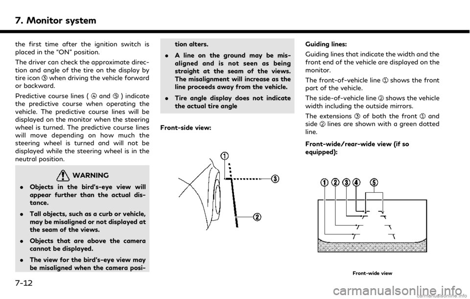
Front-side view:
Guiding lines:
Guiding lines that indicate the width and the
front end of the vehicle are displayed on the
monitor.
The front-of-vehicle line
shows the front
part of the vehicle.
The side-of-vehicle line
shows the vehicle
width including the outside mirrors.
The extensions
of both the frontand
sidelines are shown with a green dotted
line.
Front-wide/rear-wide view (if so
equipped):
Front-wide view
7-12
Page 117 of 288

the object projects over the actual backing
up course.
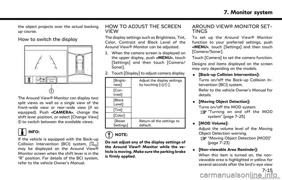
How to switch the display
The Around View® Monitor can display two
split views as well as a single view of the
front-wide view or rear-wide view (if so
equipped). Push
shift lever position, or select [Change View]
to switch between the available views.
INFO:
If the vehicle is equipped with the Back-up
Collision Intervention (BCI) system, [
]
may be displayed on the Around View®
Monitor screen when the shift lever is in the
“R” position. For details of the BCI system,
refer to the vehicle Owner’s Manual.
HOW TO ADJUST THE SCREEN
VIEW
The display settings such as Brightness, Tint,
Color, Contrast and Black Level of the
Around View® Monitor can be adjusted.
1. When the camera screen is displayed on the upper display, push
[Settings] and then touch [Camera/
Sonar].
2. Touch [Display] to adjust camera display.
[Bright-
ness] Adjust the display settings
by touching [+]/[-].
[Con-
trast]
[Black
Level]
[Tint]
[Color]
[Reset
Settings] Return all the settings to
default.
NOTE:
Do not adjust any of the display settings of
the Around View® Monitor while the ve-
hicle is moving. Make sure the parking brake
is firmly applied.
AROUND VIEW® MONITOR SET-
TINGS
To set up the Around View® Monitor
function to your preferred settings, push
[Camera/Sonar].
Touch [Camera] to set the camera function.
Designs and items displayed on the screen
may vary depending on the models. . [Back-up Collision Intervention]:
Turns on/off the Back-up Collision In-
tervention (BCI) system.
Refer to the vehicle Owner’s Manual for
details.
. [Moving Object Detection]:
Turns on/off the MOD system.
“Turning on and off the MOD
system” (page 7-25)
. [MOD Volume]:
Adjust the volume level of the Moving
Object Detection warning.
“Moving Object Detection (MOD)”
(page 7-23)
. [Non-viewable Area Reminder]:
When this item is turned on, the non-
viewable area is highlighted in yellow for
several seconds after the bird’s-eye view
7. Monitor system
7-15
Page 118 of 288
![INFINITI QX50 2019 Navigation Manual 7. Monitor system
is displayed for the first time after the
ignition switch is positioned in the “ON”
position.
. [Predictive Course Lines]:
When this item is turned on, the pre-
dictive course li INFINITI QX50 2019 Navigation Manual 7. Monitor system
is displayed for the first time after the
ignition switch is positioned in the “ON”
position.
. [Predictive Course Lines]:
When this item is turned on, the pre-
dictive course li](/manual-img/42/34995/w960_34995-117.png)
7. Monitor system
is displayed for the first time after the
ignition switch is positioned in the “ON”
position.
. [Predictive Course Lines]:
When this item is turned on, the pre-
dictive course line is displayed in the
front, rear and bird’s-eye view screen.
. [Automatic Display with Sonar]:
The automatic sonar display can be
turned on/off.
“Camera aiding sonar function
(models with Around View® Moni-
tor)” (page 7-19)
AROUND VIEW® MONITOR SYS-
TEM LIMITATIONS
WARNING
Listed below are the system limitations
for Around View® Monitor. Failure to
operate the vehicle in accordance with
these system limitations could result in
serious injury or death.
. Do not use the Around View® Moni-
tor with the outside mirrors in the
stored position, and make sure that
the trunk is securely closed when
operating the vehicle using the Around View® Monitor.
. The apparent distance between ob-
jects viewed on the Around View®
Monitor differs from the actual dis-
tance.
. The cameras are installed on the front
grille, the outside mirrors and above
the rear license plate. Do not put
anything on the vehicle that covers
the cameras.
. When washing the vehicle with high
pressure water, be sure not to spray it
around the cameras. Otherwise,
water may enter the camera unit
causing water condensation on the
lens, a malfunction, fire or an electric
shock.
. Do not strike the cameras. They are
precision instruments. Doing so could
cause a malfunction or cause damage
resulting in a fire or an electric shock.
The following are operating limitations and
do not represent a system malfunction: . The screen displayed on the Around
View® Monitor will automatically return
to the previous screen 3 minutes after
has been pushed while the
shift lever is in a position other than the
“R” (Reverse) position.
. There may be a delay when switching
between views.
. When the temperature is extremely high
or low, the screen may not display
objects clearly.
. When strong light is directly shines on
the camera, objects may not be displayed
clearly.
. The screen may flicker under fluorescent
light.
. The colors of objects on the Around
View® Monitor may differ somewhat
from the actual color of objects.
. Objects on the monitor may not be clear
and the color of the object may differ in a
dark environment.
. There may be differences in sharpness
between each camera view of the bird’s-
eye view.
. When activating the Around View®
Monitor, the icons and the messages
may not be displayed for a while.
7-16
Page 121 of 288

CAMERA AIDING SONAR
FUNCTION (models with Around
View® Monitor)
WARNING
Failure to follow the warnings and in-
structions for proper use of the sonar
function as outlined in this section could
result in serious injury or death.. The sonar is a convenience feature. It
is not a substitute for proper parking.
. This function is designed as an aid to
the driver in detecting large station-
ary objects to help avoid damaging
the vehicle.
. The driver is always responsible for
safety during parking and other man-
euvers.
. Always look around and check that it
is safe to move before parking.
. Read and understand the limitations
of the sonar as contained in this
section.
The sonar function helps to inform the driver
of large stationary objects around the vehicle when parking by issuing an audible
and visual alert.
7. Monitor system
7-19
Page 124 of 288
![INFINITI QX50 2019 Navigation Manual 7. Monitor system
item is turned to off (indicator turns off),
the front and rear sonar is deactivated.
. [FR Sensor Only]:
Turns on the front sonar and turns off
the rear sonar.
. [Interrupt Display] INFINITI QX50 2019 Navigation Manual 7. Monitor system
item is turned to off (indicator turns off),
the front and rear sonar is deactivated.
. [FR Sensor Only]:
Turns on the front sonar and turns off
the rear sonar.
. [Interrupt Display]](/manual-img/42/34995/w960_34995-123.png)
7. Monitor system
item is turned to off (indicator turns off),
the front and rear sonar is deactivated.
. [FR Sensor Only]:
Turns on the front sonar and turns off
the rear sonar.
. [Interrupt Display]:
Turns on/off the automatic sonar dis-
play.
. [Sonar Sensitivity]:
Adjust the sonar sensitivity by touching
[+]/[-].
. [Sonar Volume]:
Adjust the warning tone volume by
touching [+]/[-]
SONAR SYSTEM LIMITATIONS
WARNING
Listed below are the system limitations
for the sonar function. Failure to operate
the vehicle in accordance with these
system limitations could result in serious
injury or death.
. Inclement weather or ultrasonic
sources such as an automatic car
wash, a truck’s compressed-air brakes
or a pneumatic drill may affect the function of the system, including re-
duced performance or a false activa-
tion.
. The system is not designed to prevent
contact with small or moving objects.
. The system will not detect small
objects below the bumper, and may
not detect objects close to the bum-
per or on the ground.
. The system may not detect the fol-
lowing objects:
— Fluffy objects such as snow, cloth, cotton, grass or wool.
— Thin objects such as rope, wire or chain.
— Wedge-shaped objects.
. If your vehicle sustains damage to the
bumper fascia, leaving it misaligned or
bent, the sensing zone may be altered
causing inaccurate measurement of
objects or false alarms.
CAUTION
Excessive noise (such as audio system
volume or an open vehicle window) will
interfere with the tone and it may not be
heard.
System temporarily unavailable
When the amber markers are displayed at
the corners of the vehicle icon and the
function cannot be activated from the
Camera/Sonar setting menu (the setting
items are grayed out), the sonar system
may be malfunctioning.
SYSTEM MAINTENANCE
CAUTION
Keep the surface of the sonar sensors
(located on the front and rear bumper
fascia) free from accumulations of snow,
ice and dirt. Do not scratch the surface of
the sonar sensors when cleaning. If the
sensors are covered, the accuracy of the
sonar function will be diminished.
7-22