Page 602 of 685
7-53
7
Maintenance
After checking the fuse box in the
engine compartment, securely
install the fuse box cover. If not,
electrical failures may occur from
water leaking in.
Main fuse
If an electrical system does not oper-
ate with no blown fuse in the engine
room and inner fuse box, the main
fuse inside the battery (+) cap may
be blown.
The main fuse is heavily connected
to many other parts. In this case, we
recommend you to contact a
HYUNDAI authorised repairer.
Multi fuse
If the multi fuse is blown, it must be
removed as follows:
1. Disconnect the negative batterycable.
2. Remove the nuts shown in the pic- ture above.
3. Replace the fuse with a new one of the same rating.
4. Reinstall in the reverse order of removal.
Information
If the multi fuse is blown, we recom-
mend that you consult a HYUNDAI
authorised repairer.
i
NOTICE
OTLE078027OTLE078028
TLe UK 7.qxp 5/10/2018 1:35 PM Page 53
Page 606 of 685

7-57
7
Maintenance
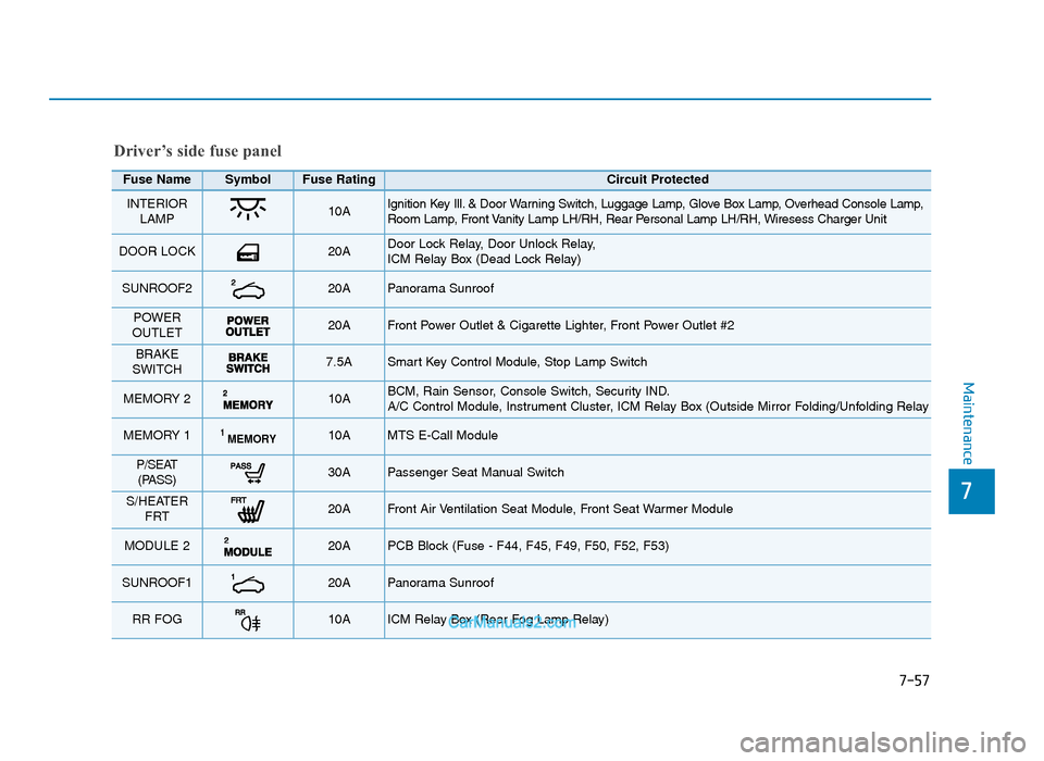
Driver’s side fuse panel
Fuse Name SymbolFuse RatingCircuit Protected
INTERIORLAMP10A Ignition Key Ill. & Door Warning Switch, Luggage Lamp, Glove Box Lamp, Overhead Console Lamp,
Room Lamp, Front Vanity Lamp LH/RH, Rear Personal Lamp LH/RH, Wiresess Charger Unit
DOOR LOCK 20A Door Lock Relay, Door Unlock Relay,
ICM Relay Box (Dead Lock Relay)
SUNROOF220A Panorama Sunroof
POWER
OUTLET 20A Front Power Outlet & Cigarette Lighter, Front Power Outlet #2
BRAKE
SWITCH 7.5A Smart Key Control Module, Stop Lamp Switch
MEMORY 2 10A BCM, Rain Sensor, Console Switch, Security IND.
A/C Control Module, Instrument Cluster, ICM Relay Box (Outside Mirror Folding/Unfolding Relay
MEMORY 1MEMORY110A MTS E-Call Module
P/SEAT (PASS)30A Passenger Seat Manual Switch
S/HEATER FRT 20A Front Air Ventilation Seat Module, Front Seat Warmer Module
MODULE 2 20A PCB Block (Fuse - F44, F45, F49, F50, F52, F53)
SUNROOF120A Panorama Sunroof
RR FOG10A ICM Relay Box (Rear Fog Lamp Relay)
TLe UK 7.qxp 5/10/2018 1:36 PM Page 57
Page 613 of 685

Maintenance
7-64
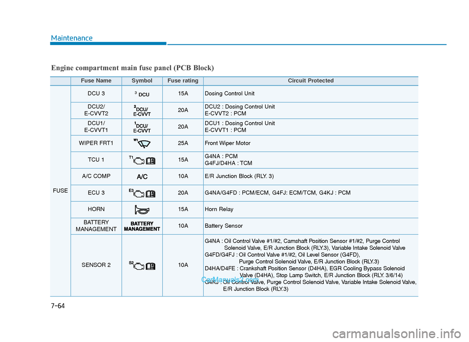
Engine compartment main fuse panel (PCB Block)
Fuse Name SymbolFuse ratingCircuit Protected
FUSE
DCU 3DCU315A Dosing Control Unit
DCU2/
E-CVVT220A DCU2 : Dosing Control Unit
E-CVVT2 : PCM
DCU1/
E-CVVT120A DCU1 : Dosing Control Unit
E-CVVT1 : PCM
WIPER FRT125A Front Wiper Motor
TCU 115A G4NA : PCM
G4FJ/D4HA : TCM
A/C COMP10AE/R Junction Block (RLY. 3)
ECU 320A G4NA/G4FD : PCM/ECM, G4FJ: ECM/TCM, G4KJ : PCM
HORN15A Horn Relay
BATTERY
MANAGEMENT10A Battery Sensor
SENSOR 210A
G4NA : Oil Control Valve #1/#2, Camshaft Position Sensor #1/#2, Purge Control Solenoid Valve, E/R Junction Block (RLY.3), Variable Intake Solenoid Valve
G4FD/G4FJ : Oil Control Valve #1/#2, Oil Level Sensor (G4FD), Purge Control Solenoid Valve, E/R Junction Block (RLY.3)
D4HA/D4FE : Crankshaft Position Sensor (D4HA), EGR Cooling Bypass Solenoid Valve (D4HA), Stop Lamp Switch, E/R Junction Block (RLY. 3/6/14)
G4KJ : Oil Control Valve, Purge Control Solenoid Valve, Variable Intake Solenoid Valve, E/R Junction Block (RLY.3)
TLe UK 7.qxp 5/10/2018 1:38 PM Page 64
Page 614 of 685

7-65
7
Maintenance
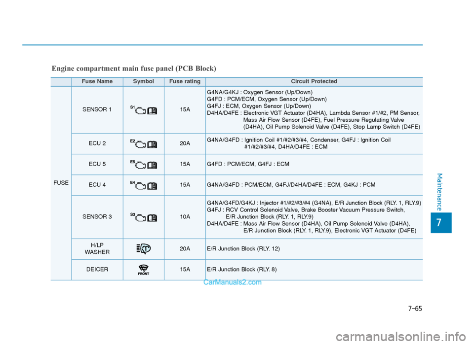
Fuse Name SymbolFuse ratingCircuit Protected
FUSE
SENSOR 115A
G4NA/G4KJ : Oxygen Sensor (Up/Down)
G4FD : PCM/ECM, Oxygen Sensor (Up/Down)
G4FJ : ECM, Oxygen Sensor (Up/Down)
D4HA/D4FE : Electronic VGT Actuator (D4HA), Lambda Sensor #1/#2, PM Sensor,Mass Air Flow Sensor (D4FE), Fuel Pressure Regulating Valve
(D4HA), Oil Pump Solenoid Valve (D4FE), Stop Lamp Switch (D4FE)
ECU 220A G4NA/G4FD : Ignition Coil #1/#2/#3/#4, Condenser, G4FJ : Ignition Coil #1/#2/#3/#4, D4HA/D4FE : ECM
ECU 515A G4FD : PCM/ECM, G4FJ : ECM
ECU 415A G4NA/G4FD : PCM/ECM, G4FJ/D4HA/D4FE : ECM, G4KJ : PCM
SENSOR 310A
G4NA/G4FD/G4KJ : Injector #1/#2/#3/#4 (G4NA), E/R Junction Block (RLY. 1, RLY.9)
G4FJ : RCV Control Solenoid Valve, Brake Booster Vacuum Pressure Switch, E/R Junction Block (RLY. 1, RLY.9)
D4HA/D4FE : Mass Air Flow Sensor (D4HA), Oil Pump Solenoid Valve (D4HA), E/R Junction Block (RLY. 1, RLY.9), Electronic VGT Actuator (D4FE)
H/LP
WASHER20AE/R Junction Block (RLY. 12)
DEICER15A E/R Junction Block (RLY. 8)
Engine compartment main fuse panel (PCB Block)
TLe UK 7.qxp 5/10/2018 1:38 PM Page 65
Page 615 of 685
Maintenance
7-66
Fuse Name SymbolFuse ratingCircuit Protected
FUSE
FUEL
PUMPFUEL
PUMP20A E/R Junction Block (RLY.14)
MODULE 17.5A D4HA/D4FE : Glow Relay Unit, Fuel Filter Warning Sensor,
E/R Junction Block (RLY. 10)
B/ALARM HORN10A E/R Junction Block (RLY. 7)
ACTIVE
BONNET10AG4FD/G4FJ/D4HA/D4FE : Active Bonnet Lift Control Module
ABS 310A ABS Control Module, ESP Control Module
MODULE 215A G4FJ : Vacuum Pump
POWER
OUTLET FRTPOWER
OUTLET FRT20AFront Power Outlet & Cigarette Light
ECU 610A
G4NA/G4FD : ECM/PCM
G4FJ : ECM
D4HA/D4FE : ECM, Oil Level Sensor
G4KJ : PCM
Engine compartment main fuse panel (PCB Block)
TLe UK 7.qxp 5/10/2018 1:38 PM Page 66
Page 616 of 685
7-67
7
Maintenance
Fuse Name SymbolFuse ratingCircuit Protected
FUSE
TCU 215A [A/T] Transaxle Range Switch,TCM, ATM Shift Lever
[M/T] Back-Up Lamp Switch
B/UP LAMP10A Transaxle Range Switch, Electro Chromic Mirror,
Rear Combination Lamp (IN) LH/RH, TCM, Back-Up Lamp Switch,
MTS E-Call Module, Smart Junction Block (IPS Control Module)
POWER
OUTLET REARPOWER
OUTLET REAR20ARear Power Outlet
WIPER FRT210A BCM, G4NA/G4KJ : PCM/ECM
MODULE 3MODULE310A E/R Junction Block (RLY. 14)
ECU 1E130AEngine Control Relay
Engine compartment main fuse panel (PCB Block)
TLe UK 7.qxp 5/10/2018 1:38 PM Page 67
Page 629 of 685
7-80
Maintenance
Rear fog lamp (if equipped)
1. Remove the socket from theassembly by turning the socket
counterclockwise until the tabs on
the socket align with the slots on
the assembly.
2. Remove the bulb from the socket by pressing it in and rotating it
counterclockwise until the tabs on
the bulb align with the slots in the
socket. Pull the bulb out of the
socket.
3. Insert a new bulb in the socket.
4. Reinstall the light assembly to the body of the vehicle.
High mounted stop lamp
replacement
If the high mounted stop lamp does not
operate, we recommend that you con-
tact a HYUNDAI authorised repairer.
License plate light bulb
replacement
1. Loosen the lens retaining screwswith a screwdriver.
2. Remove the lens.
3. Remove the bulb by pulling it straight out.
4. Install a new bulb.
5. Reinstall the lens securely with the lens retaining screws.
OTLE078040OTLE078041
TLe UK 7.qxp 5/10/2018 1:39 PM Page 80
Page 651 of 685

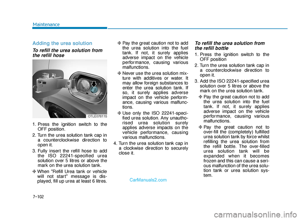
Adding the urea solution
To refill the urea solution fromthe refill hose
1. Press the ignition switch to the
OFF position.
2. Turn the urea solution tank cap in a counterclockwise direction to
open it.
3. Fully insert the refill hose to add the ISO 22241-specified urea
solution over 5 litres or above the
mark on the urea solution tank.
❈ When "Refill Urea tank or vehicle
will not start" message is dis-
played, fill up urea at least 6 litres. ❈
Pay the great caution not to add
the urea solution into the fuel
tank. If not, it surely applies
adverse impact on the vehicle
performance, causing various
malfunctions.
❈ Never use the urea solution mix-
ture with additives or water. It
may allow foreign substances to
enter the urea solution tank. If
so, it surely applies adverse
impact on the vehicle perform-
ance, causing various malfunc-
tions.
❈ Use only the ISO 22241-speci-
fied urea solution. Any unautho-
rised urea solution surely
applies adverse impacts on the
vehicle performance, causing
various malfunctions.
4. Turn the urea solution tank cap in a clockwise direction to securely
close it.
To refill the urea solution fromthe refill bottle
1. Press the ignition switch to the
OFF position
2. Turn the urea solution tank cap in a counterclockwise direction to
open it.
3. Add the ISO 22241-specified urea solution over 5 litres or above the
mark on the urea solution tank.
❈ Pay the great caution not to add
the urea solution into the fuel
tank. If not, it surely applies
adverse impact on the vehicle
performance, causing various
malfunctions.
❈ Pay the great caution not to
over-fill the (completely) fulfilled
urea solution tank by force whilst
refilling the urea solution from
the refill bottle. The over-filled
urea solution tank will be
expanded when it becomes
frozen and this can cause a seri-
ous malfunction of the urea solu-
tion tank or urea solution sys-
tem.
7-102
Maintenance
OTLE078115
TLe UK 7.qxp 6/12/2018 2:51 PM Page 102