Page 259 of 526
3-112
Convenient features of your vehicle For maximum defrosting, set thetemperature control to the extreme
right/hot position and the fan speed
control to the highest speed.
If warm air to the floor is desired whilst defrosting or defogging, set
the mode to the floor-defrost posi-
tion.
Before driving, clear all snow and ice from the windscreen, rear win-
dow, outside rear view mirrors, and
all side windows.
Clear all snow and ice from the bonnet and air inlet in the cowl grill
to improve heater and defroster
efficiency and to reduce the proba-
bility of fogging up inside of the
windscreen.
Automatic climate control
system
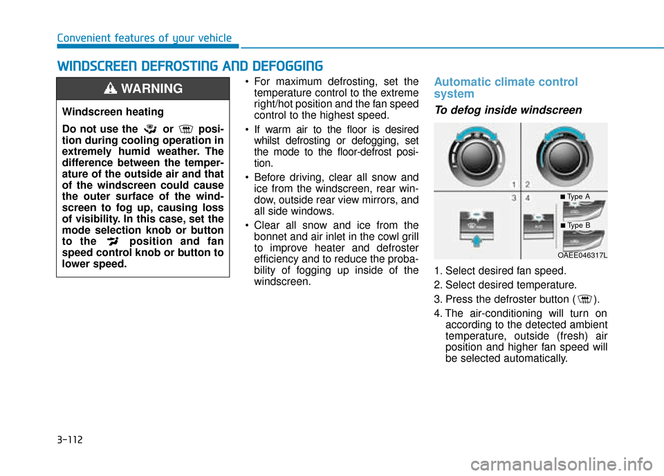
To defog inside windscreen
1. Select desired fan speed.
2. Select desired temperature.
3. Press the defroster button ( ).
4. The air-conditioning will turn on according to the detected ambient
temperature, outside (fresh) air
position and higher fan speed will
be selected automatically.
W
WI
IN
N D
DS
SC
C R
R E
EE
EN
N
D
D E
EF
FR
R O
O S
ST
T I
IN
N G
G
A
A N
N D
D
D
D E
EF
FO
O G
GG
GI
IN
N G
G
Windscreen heating
Do not use the or posi-
tion during cooling operation in
extremely humid weather. The
difference between the temper-
ature of the outside air and that
of the windscreen could cause
the outer surface of the wind-
screen to fog up, causing loss
of visibility. In this case, set the
mode selection knob or button
to the position and fan
speed control knob or button to
lower speed.
WARNING
OAEE046317L
■Type A
■Type B
Page 261 of 526
3-114
Convenient features of your vehicle
The climate control information
screen will blink 3 times. It indicates
that the defogging logic is cancelled
or returned to the programmed sta-
tus.
If the battery has been discharged or
disconnected, it resets to the defog
logic status.
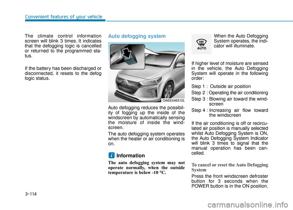
Auto defogging system
Auto defogging reduces the possibil-
ity of fogging up the inside of the
windscreen by automatically sensing
the moisture of inside the wind-
screen.
The auto defogging system operates
when the heater or air conditioning is
on.
Information
The auto defogging system may not
operate normally, when the outside
temperature is below -10 °C. When the Auto Defogging
System operates, the indi-
cator will illuminate.
If higher level of moisture are sensed
in the vehicle, the Auto Defogging
System will operate in the following
order:
Step 1 : Outside air position
Step 2 : Operating the air conditioning
Step 3 : Blowing air toward the wind- screen
Step 4 : Increasing air flow toward the windscreen
If the air conditioning is off or recircu-
lated air position is manually selected
whilst Auto Defogging System is ON,
the Auto Defogging System Indicator
will blink 3 times to signal that the
manual operation has been can-
celled.To cancel or reset the Auto Defogging
System
Press the front windscreen defroster
button for 3 seconds when the
POWER button is in the ON position.
i
OAEE046312L
Page 262 of 526
3-115
Convenient features of your vehicle
3
When the Auto Defogging System is
cancelled, ADS OFF symbol will
blink 3 times and the ADS OFF will
be displayed on the climate control
information screen.
When the Auto Defogging System is
reset, ADS OFF symbol will blink 6
times without a signal.
Information
• When the air conditioning is turnedon by Auto defogging system, if you
try to turn off the air conditioning, the
indicator will blink 3 times and the air
conditioning will not be turned off.
• For efficiency, do not select recircu- lated air position whilst Auto defog-
ging system is operating.
Do not remove the sensor cover
located on the upper end of the
windscreen glass.
Damage to system parts could
occur and may not be covered by
your vehicle warranty.
Sunroof inside air recirculation
(if equipped)
If the sunroof opens whilst the heater
or Air Conditioning system operates,
the outside (fresh) air will be select-
ed automatically for ventilating the
car. Then, if you select the recirculat-
ed air position, the outside (fresh) air
will be selected automatically after 3
minutes.
If you close the sunroof, the intake
mode will be changed to the previous
selected mode.
NOTICE
i
C C L
LI
IM
M A
AT
TE
E
C
C O
O N
NT
TR
R O
O L
L
A
A D
DD
DI
IT
T I
IO
O N
NA
AL
L
F
F E
E A
A T
TU
U R
RE
ES
S
Page 268 of 526
3-121
Convenient features of your vehicle
3
To prevent damage to the Power
Outlets :
Use the power outlet only whenthe vehicle is in the ready ( )
mode and remove the accessory
plug after use. Using the acces-
sory plug for prolonged periods
of time with the vehicle off could
cause the battery to discharge.
Only use 12V electric accessories which are less than 180 W(Watt) in
electric capacity.
Adjust the air-conditioner or heater to the lowest operating
level when using the power outlet.
Close the cover when not in use.
Some electronic devices can cause electronic interference
when plugged into a vehicle’s
power outlet. These devices may
cause excessive audio static
and malfunctions in other elec-
tronic systems or devices used
in your vehicle.
(Continued)(Continued)
Push the plug in as far as it will
go. If good contact is not made,
the plug may overheat and the
fuse may open.
Plug in battery equipped electri- cal/electronic devices with
reverse current protection. The
current from the battery may
flow into the vehicle's electri-
cal/electronic system and cause
system malfunction.
Wireless mobile phone charg-
ing system (if equipped)
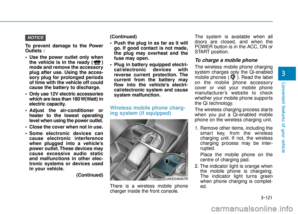
There is a wireless mobile phone
charger inside the front console. The system is available when all
doors are closed, and when the
POWER button is in the ACC, ON or
START position.
To charge a mobile phone
The wireless mobile phone charging
system charges only the Qi-enabled
mobile phones ( ). Read the label
on the mobile phone accessory
cover or visit your mobile phone
manufacturer’s website to check
whether your mobile phone supports
the Qi technology.
The wireless charging process starts
when you put a Qi-enabled mobile
phone on the wireless charging unit.
1. Remove other items, including the
smart key, from the wireless
charging unit. If not, the wireless
charging process may be inter-
rupted.
Place the mobile phone on the
centre of charging pad.
2. The indicator light is orange when the mobile phone is chargeing.
The indicator light turns green
when phone charging is complet-
ed.
NOTICE
OAEE046407R
Page 454 of 526
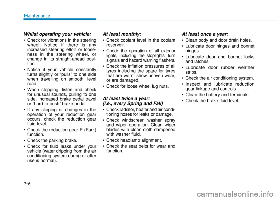
7-6
Maintenance
Whilst operating your vehicle:
Check for vibrations in the steeringwheel. Notice if there is any
increased steering effort or loose-
ness in the steering wheel, or
change in its straight-ahead posi-
tion.
Notice if your vehicle constantly turns slightly or “pulls” to one side
when travelling on smooth, level
road.
When stopping, listen and check for unusual sounds, pulling to one
side, increased brake pedal travel
or “hard-to-push” brake pedal.
If any slipping or changes in the operation of your reduction gear
occurs, check the reduction gear
fluid level.
Check the reduction gear P (Park) function.
Check the parking brake.
Check for fluid leaks under your vehicle (water dripping from the air
conditioning system during or after
use is normal).
At least monthly:
Check coolant level in the coolantreservoir.
Check the operation of all exterior lights, including the stoplights, turn
signals and hazard warning flashers.
Check the inflation pressures of all tyres including the spare for tyres
that are worn, show uneven wear,
or are damaged.
Check for loose wheel lug nuts.
At least twice a year: (i.e., every Spring and Fall)
Check radiator, heater and air condi-
tioning hoses for leaks or damage.
Check windscreen washer spray and wiper operation. Clean wiper
blades with clean cloth dampened
with washer fluid.
Check headlamp alignment.
Check the seat belts for wear and function.
At least once a year:
Clean body and door drain holes.
Lubricate door hinges and bonnethinges.
Lubricate door and bonnet locks and latches.
Lubricate door rubber weather strips.
Check the air conditioning system.
Inspect and lubricate reduction gear linkage and controls.
Clean the battery and terminals.
Check the brake fluid level.
Page 457 of 526
7-9
7
Maintenance
C
CO
O O
OL
LA
A N
N T
T
The high-pressure cooling system
has a reservoir filled with year-round
antifreeze coolant. The reservoir is
filled at the factory.
Check the antifreeze protection and
coolant level at least once a year, at
the beginning of the winter season
and before travelling to a colder cli-
mate.Checking the coolant level
Check the condition and connections
of all cooling system hoses and
heater hoses. Replace any swollen
or deteriorated hoses. The coolant level should be filled
between the MAX and the MIN
marks on the side of the coolant
reservoir when the parts in the motor
compartment is cool.
If the coolant level is low, add enough
distilled (deionized) water to bring
the level to the MAX mark, but do not
overfill. If frequent additions are
required, we recommend that you
see a HYUNDAI authorised repairer
for a cooling system inspection.
OAEE076002L
Page 487 of 526
7-39
7
Maintenance
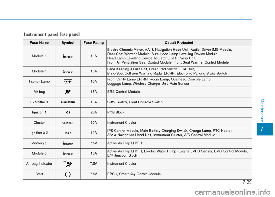
Instrument panel fuse panel
Fuse NameSymbolFuse RatingCircuit Protected
Module 5MODULE510A
Electro Chromic Mirror, A/V & Navigation Head Unit, Audio, Driver IMS Module,
Rear Seat Warmer Module, Auto Head Lamp Levelling Device Module,
Head Lamp Levelling Device Actuator LH/RH, Vess Unit,
Front Air Ventilation Seat Control Module, Front Seat Warmer Control Module
Module 4MODULE410ALane Keeping Assist Unit, Crash Pad Switch, FCA Unit,
Blind-Spot Collision Warning Radar LH/RH, Electronic Parking Brake Switch
Interior Lamp10AFront Vanity Lamp LH/RH, Room Lamp, Overhead Console Lamp,
Luggage Lamp, Wireless Charger Unit, Rain Sensor
Air bag15ASRS Control Module
E- Shifter 1 10ASBW Switch, Front Console Switch
Ignition 1IG125APCB Block
ClusterCLUSTER10AInstrument Cluster
Ignition 3 2 10AIPS Control Module, Main Battery Charging Switch, Charge Lamp, PTC Heater,
A/V & Navigation Head Unit, Instrument Cluster, A/C Control Module
Memory 2MEMORY27.5AActive Air Flap LH/RH
Module 8MODULE810AActive Air Flap LH/RH, Electric Water Pump (Engine), VPD Sensor, BMS Control Module,
E/R Junction Block
Air bag IndicatorIND7.5AInstrument Cluster
Start7.5AEPCU, Smart Key Control Module
Page 489 of 526
7-41
7
Maintenance
Fuse NameSymbolFuse RatingCircuit Protected
Heated Steering15ABCM
Sunroof20ASunroof Motor
Power WindowRight-handRH25APower Window (RH) Relay, Passenger Power Window Switch, Driver Safety Power Window
Power Window Left-handLH25APower Window (LH) Relay, Driver Power Window Switch,
Passenger Safety Power Window Module
Button Start 227.5AImmobiliser Module, Smart Key Control Module, Start/Stop Button Switch
Brake SwitchBRAKE
SWITCH7.5AStop Lamp Switch, Smart Key Control Module
OBC10AOBC
Air conditioner7.5AIonizer, A/C Control Module, Electronic A/C Compressor, E/R Junction Block
Washer15AMultifunction Switch
Seat Heater RearRR25ARear Seat Warmer Module
Charger10ACCM Unit(for Europe), Normal Charging Connector Lamp(except Europe),
ICM Relay Box (Charging Connector Lock/Unlock Relay)
Power Seat DriverDRV30ADriver Seat Manual Switch, Driver IMS Module
Instrument panel fuse panel