Page 49 of 526
H49
Distance to empty that is displayedon the instrument cluster after
completing a recharge may vary
significantly depending on previ-
ous operating patterns.
When previous driving patterns
include high speed driving, result-
ing in the high voltage battery
using more electricity than usual,
the estimated distance to empty is
reduced. When the high voltage
battery uses little electricity in ECO
mode, the estimated distance to
empty increases.
Distance to empty may depend on many factors such as the charge
amount of the high voltage battery,
weather, temperature, durability of
the battery, geographical features,
and driving style.
Natural degradation may occur with the high voltage battery
depending on the number of years
the vehicle is used. This may
reduce the distance to empty.When destination is set
When the destination is set, the dis-
tance to empty may change. The dis-
tance to empty is recalculated using
the information of the destination.
However, the distance to empty may
vary significantly based on traffic
conditions, driving habits, and condi-
tion of the vehicle.
Tips for Improving Distance to
Empty
If you operate the air conditioner/heater too much, the driving bat-
tery uses too much electricity. This
may reduce the distance to empty.
Therefore, it is recommended that
you set the cabin temperature to
22°C AUTO. This setting that has
been certified by various assess-
ment tests to maintain optimal
energy consumption rates whilst
keeping the temperature fresh.
Turn OFF the heater and air condi-
tioner if you do not need them.
Depress and hold the accelerator pedal to maintain speed and drive
economically.
Gradually depress and release the accelerator pedal when accelerat-
ing or decelerating.
Always maintain specified tyre pressures.
Do not use unnecessary electrical components whilst driving.
Do not load unnecessary items in the vehicle.
Do not mount parts that may increase air resistance.
Page 61 of 526
H61
Information
• The Aux. Battery Saver+ activatesmaximum of 20 minutes. If the Aux.
Battery Saver+ function activates
more than 10 times consecutively in
the Automatic Mode, the function
will stop activating, judging that
there is a problem with the auxiliary
battery. In this case, drive the vehi-
cle for some period of time. The
function will start activating if the
auxiliary battery returns to normal.
• The Aux. Battery Saver+ function cannot prevent battery discharge if
the auxiliary battery is damaged,
worn out, used as a power supply or
unauthorised electronic devises are
used.
• If the Aux. Battery Saver+ function was activated, a message will be dis-
played on the instrument cluster
and the high voltage battery level
may have decreased.
System Setting
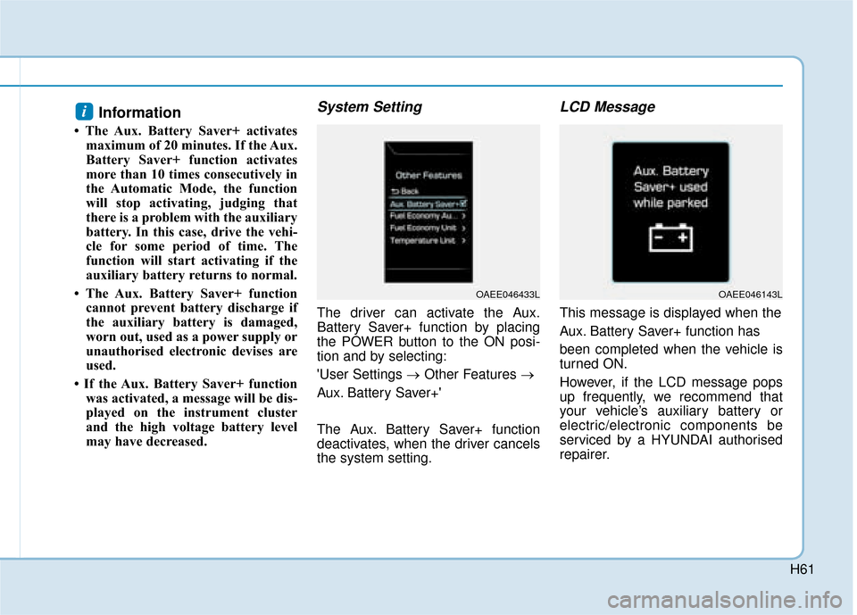
The driver can activate the Aux.
Battery Saver+ function by placing
the POWER button to the ON posi-
tion and by selecting:
'User Settings → Other Features →
Aux. Battery Saver+'
The Aux. Battery Saver+ function
deactivates, when the driver cancels
the system setting.
LCD Message
This message is displayed when the
Aux. Battery Saver+ function has
been completed when the vehicle is
turned ON.
However, if the LCD message pops
up frequently, we recommend that
your vehicle’s auxiliary battery or
electric/electronic components be
serviced by a HYUNDAI authorised
repairer.
i
OAEE046143LOAEE046433L
Page 64 of 526
H64
Other Precautions for Electric
Vehicle
When you paint or apply heat treat-ment to the vehicle as a result of
an accident, the performance of
the high voltage battery can be
reduced.
If heat treatment is required, we
recommend that you contact a
HYUNDAI authorised repairer.
When you clean the motor com- partment, do not use high pressure
water to wash. This may cause an
electric shock due to a discharge in
high voltage electricity, or damage
the vehicle's electric system. Do not use, remodel, or install non-
genuine parts. This may damage
the electric power system.
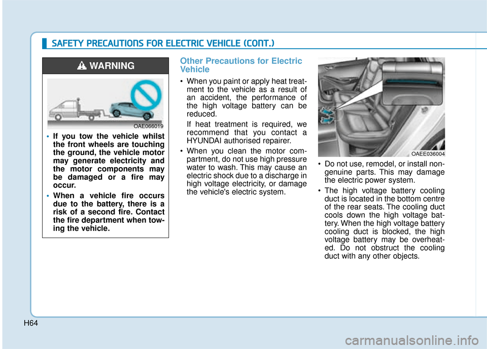
The high voltage battery cooling duct is located in the bottom centre
of the rear seats. The cooling duct
cools down the high voltage bat-
tery. When the high voltage battery
cooling duct is blocked, the high
voltage battery may be overheat-
ed. Do not obstruct the cooling
duct with any other objects.
OAEE036004
S
SA
A F
FE
E T
T Y
Y
P
P R
R E
EC
CA
A U
U T
TI
IO
O N
NS
S
F
F O
O R
R
E
E L
LE
E C
CT
T R
R I
IC
C
V
V E
EH
H I
IC
C L
LE
E
(
( C
C O
O N
NT
T.
.)
)
If you tow the vehicle whilst
the front wheels are touching
the ground, the vehicle motor
may generate electricity and
the motor components may
be damaged or a fire may
occur.
When a vehicle fire occurs
due to the battery, there is a
risk of a second fire. Contact
the fire department when tow-
ing the vehicle.
WARNING
OAE066019
Page 66 of 526
O
OW
W N
NE
ER
R '
'S
S
M
M A
AN
N U
U A
AL
L
O
Op
pe
er
ra
a t
ti
io
o n
n
M
M a
ai
in
n t
te
e n
n a
an
n c
ce
e
S
S p
pe
ec
ci
if
f i
ic
c a
a t
ti
io
o n
ns
s
The information in this Owner's Manual is current at the time of pub-
lication. However, the right to amend specifications without notice or
obligation to incorporate such amendments into vehicles already
produced is reserved.
This manual applies to all models of this vehicle and includes descrip-
tions and explanations of optional as well as standard equipment. As
a result, some of the equipment operating descriptions referred to may
not apply to the particular vehicle with which this manual is supplied.
We recommend that you contact a HYUNDAI authorised repairer for
information regarding current standard and optional equipment levels.
Page 135 of 526
2-57
Safety system of your vehicle
2
SRS warning light
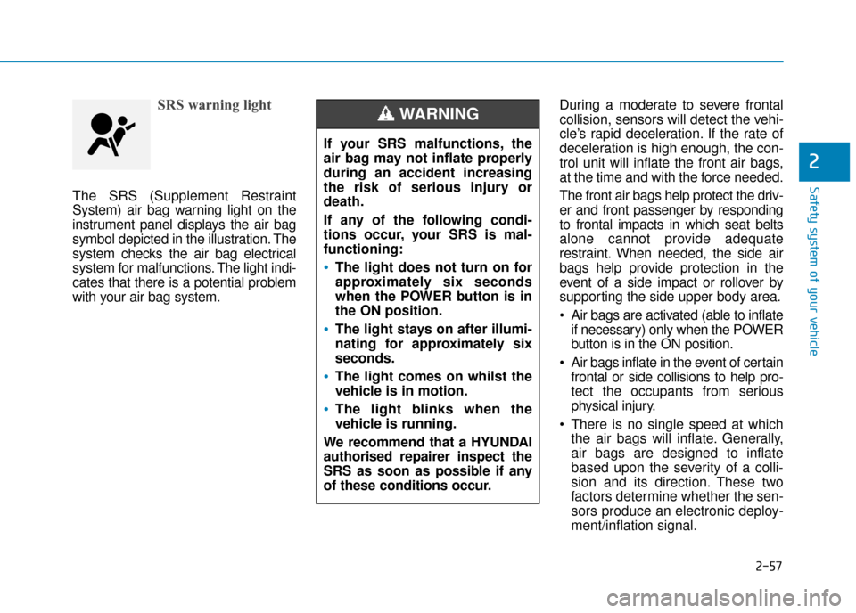
The SRS (Supplement Restraint
System) air bag warning light on the
instrument panel displays the air bag
symbol depicted in the illustration. The
system checks the air bag electrical
system for malfunctions. The light indi-
cates that there is a potential problem
with your air bag system.During a moderate to severe frontal
collision, sensors will detect the vehi-
cle’s rapid deceleration. If the rate of
deceleration is high enough, the con-
trol unit will inflate the front air bags,
at the time and with the force needed.
The front air bags help protect the driv-
er and front passenger by responding
to frontal impacts in which seat belts
alone cannot provide adequate
restraint. When needed, the side air
bags help provide protection in the
event of a side impact or rollover by
supporting the side upper body area.
Air bags are activated (able to inflate
if necessary) only when the POWER
button is in the ON position.
Air bags inflate in the event of certain frontal or side collisions to help pro-
tect the occupants from serious
physical injury.
There is no single speed at which the air bags will inflate. Generally,
air bags are designed to inflate
based upon the severity of a colli-
sion and its direction. These two
factors determine whether the sen-
sors produce an electronic deploy-
ment/inflation signal.
If your SRS malfunctions, the
air bag may not inflate properly
during an accident increasing
the risk of serious injury or
death.
If any of the following condi-
tions occur, your SRS is mal-
functioning:
The light does not turn on for
approximately six seconds
when the POWER button is in
the ON position.
The light stays on after illumi-
nating for approximately six
seconds.
The light comes on whilst the
vehicle is in motion.
The light blinks when the
vehicle is running.
We recommend that a HYUNDAI
authorised repairer inspect the
SRS as soon as possible if any
of these conditions occur.
WARNING
Page 178 of 526
3-31
Convenient features of your vehicle
3
Resetting the sunroof
The sunroof may need to be reset if
the following conditions occur:
- Battery is discharged or disconnect-ed or the related fuse has been
replaced or disconnected
- The one-touch sliding function of the sunroof does not normally operate
To reset the sunroof, perform the fol-
lowing steps:
1. Place the POWER button to the ON position or when the vehicle is
in the ready ( ) mode. It is rec-
ommended to reset the sunroof
whilst the vehicle is in the ready
( ) mode.
2. Push the control lever forward. The sunroof will close completely or tilt
depending on the condition of the
sunroof.
3. Release the control lever until the sunroof does not move. 4. Push the control lever forward
about 10 seconds.
- When the sunroof is in the close position :
The glass will tilt and slightly move up and down.
- When the sunroof is in the tilt posi- tion:
The glass will slightly move up and down.
Do not release the lever until the
operation is completed.
If you release the lever during opera-
tion, try again from step 2.
5. Within 3 seconds, push the control lever forward until the sunroof
operates as follows:
Tilt down → Slide Open → Slide
Close.
Do not release the lever until the
operation is completed.
If you release the lever during opera-
tion, try again from step 2. 6. Release the sunroof control lever
after all operation has completed.
The sunroof system has been
reset.
Information
• If the sunroof does not reset whenthe vehicle battery is disconnected
or discharged, or related fuse is
blown, the sunroof may not operate
normally.
• For more detailed information, we recommend that you contact a
HYUNDAI authorised repairer.
i
Page 184 of 526
3-37
Convenient features of your vehicle
3
Gauges and meters
Speedometer
The speedometer indicates the
speed of the vehicle and is calibratedin kilometers per hour (km/h) and/or
miles per hour (MPH).
The speedometer is displayed differ-
ently according to the selected drive
mode in the Drive Mode Integrated
Control System.
For more details, refer to “Drive
Mode Integrated Control System”
in chapter 5.
ECO guide
The ECO guide shows the energy
consumption rate of the vehicle and
the charge/discharge status of the
regenerative brakes.
It shows the energy consumption rate
of the vehicle when driving uphill or
accelerating. The more electric ener-
gy is used, the higher the gauge level.
It shows the energy consumption
rate during normal driving condition.
OAEQ046008
OAEE046169R
■
NORMAL/ECO mode selected
OAE046104N
■SPORT mode selected
Page 187 of 526
3-40
Convenient features of your vehicle
Distance to empty
The distance to empty is the esti-mated distance the vehicle can be
driven with remaining level of the
high voltage battery.
For more details, refer to
“Distance to Empty” in the
Electric Vehicle Guide.
The distance to empty is displayed differently according to the selected
drive mode in the Drive Mode
Integrated Control System. For
more details, refer to “Drive Mode
Integrated Control System” in
chapter 5.
Reduction gear shift indicator
This indicator displays which gear is
selected.
Shift indicator pop-up (if equipped)
The pop-up indicates the current
gear position displayed in the cluster
for about 2 seconds when shifting
into other positions (P/R/N/D).
OAEE046103
OAEE046104R
OAE048475N/OAEE047126R
■ NORMAL/
ECO mode selected ■
SPORT mode selected