Page 100 of 490
GARAGE DOOR OPENER — IF EQUIPPED
HomeLink replaces up to three remote controls (hand-held
transmitters) that operate devices such as garage door
openers, motorized gates, lighting or home security sys-
tems. The HomeLink unit operates off your vehicle’s
battery.
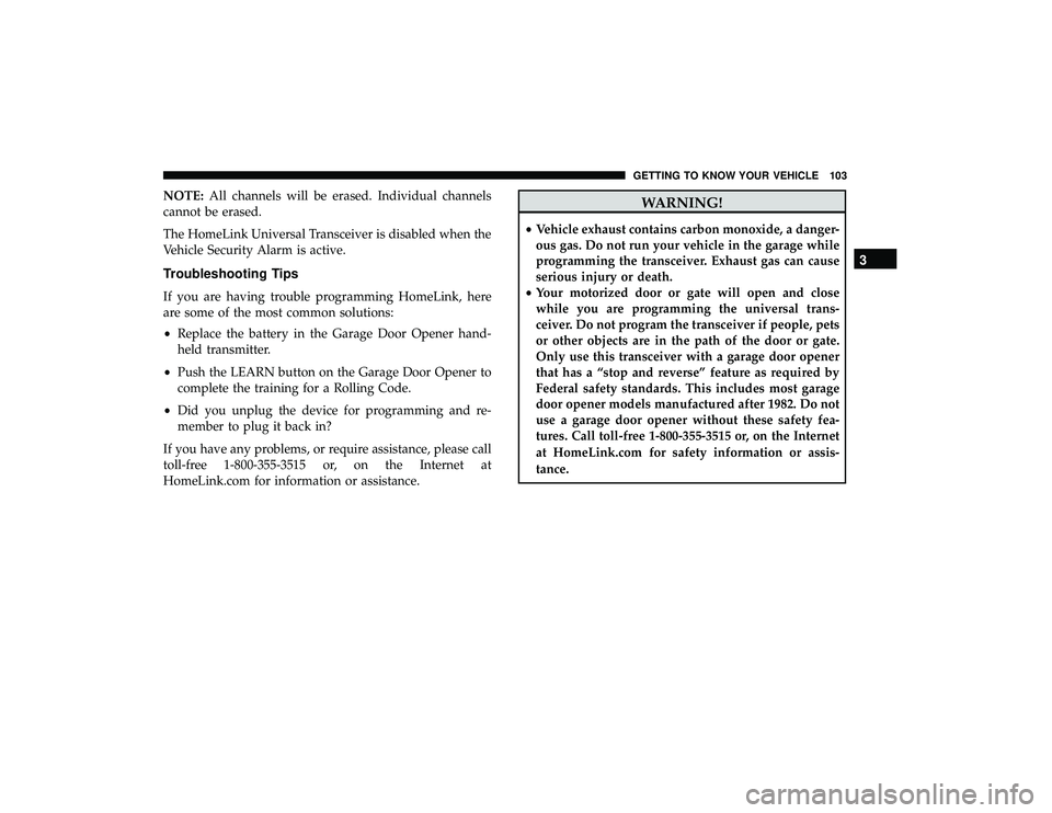
The HomeLink buttons, located on either the overhead
console, headliner or sunvisor, designate the three different
HomeLink channels. The HomeLink indicator is located
above the center button.NOTE:HomeLink is disabled when the Vehicle Security
Alarm is active.
Before You Begin Programming HomeLink
Be sure that your vehicle is parked outside of the garage
before you begin programming.
For more efficient programming and accurate transmission
of the radio-frequency signal, it is recommended that a new
battery be placed in the hand-held transmitter of the device
that is being programmed to the HomeLink system.
HomeLink Buttons/Overhead Consoles
HomeLink Buttons/Sunvisor/Headliner
98 GETTING TO KNOW YOUR VEHICLE
Page 105 of 490

NOTE:All channels will be erased. Individual channels
cannot be erased.
The HomeLink Universal Transceiver is disabled when the
Vehicle Security Alarm is active.
Troubleshooting Tips
If you are having trouble programming HomeLink, here
are some of the most common solutions:
• Replace the battery in the Garage Door Opener hand-
held transmitter.
• Push the LEARN button on the Garage Door Opener to
complete the training for a Rolling Code.
• Did you unplug the device for programming and re-
member to plug it back in?
If you have any problems, or require assistance, please call
toll-free 1-800-355-3515 or, on the Internet at
HomeLink.com for information or assistance.
WARNING!
• Vehicle exhaust contains carbon monoxide, a danger-
ous gas. Do not run your vehicle in the garage while
programming the transceiver. Exhaust gas can cause
serious injury or death.
• Your motorized door or gate will open and close
while you are programming the universal trans-
ceiver. Do not program the transceiver if people, pets
or other objects are in the path of the door or gate.
Only use this transceiver with a garage door opener
that has a “stop and reverse” feature as required by
Federal safety standards. This includes most garage
door opener models manufactured after 1982. Do not
use a garage door opener without these safety fea-
tures. Call toll-free 1-800-355-3515 or, on the Internet
at HomeLink.com for safety information or assis-
tance.
3
GETTING TO KNOW YOUR VEHICLE 103
Page 117 of 490

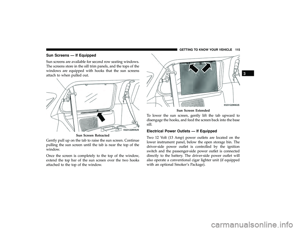
Sun Screens — If Equipped
Sun screens are available for second row seating windows.
The screens store in the sill trim panels, and the tops of the
windows are equipped with hooks that the sun screens
attach to when pulled out.
Gently pull up on the tab to raise the sun screen. Continue
pulling the sun screen until the tab is near the top of the
window.
Once the screen is completely to the top of the window,
extend the top bar of the sun screen over the two hooks
attached to the top of the window.To lower the sun screen, gently lift the tab upward to
disengage the hooks, and feed the screen back into the base
sill.
Electrical Power Outlets — If Equipped
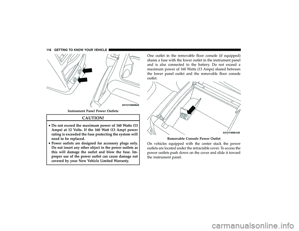
Two 12 Volt (13 Amp) power outlets are located on the
lower instrument panel, below the open storage bin. The
driver-side power outlet is controlled by the ignition
switch and the passenger-side power outlet is connected
directly to the battery. The driver-side power outlet will
also operate a conventional cigar lighter unit (if equipped
with an optional Smoker’s Package).Sun Screen Retracted
Sun Screen Extended
3
GETTING TO KNOW YOUR VEHICLE 115
Page 118 of 490

CAUTION!
•Do not exceed the maximum power of 160 Watts (13
Amps) at 12 Volts. If the 160 Watt (13 Amp) power
rating is exceeded the fuse protecting the system will
need to be replaced.
•
Power outlets are designed for accessory plugs only.
Do not insert any other object in the power outlets as
this will damage the outlet and blow the fuse. Im-
proper use of the power outlet can cause damage not
covered by your New Vehicle Limited Warranty.
One outlet in the removable floor console (if equipped)
shares a fuse with the lower outlet in the instrument panel
and is also connected to the battery. Do not exceed a
maximum power of 160 Watts (13 Amps) shared between
the lower panel outlet and the removable floor console
outlet.
On vehicles equipped with the center stack the power
outlets are located under the retractable cover. To access the
power outlets push down on the cover and slide it toward
the instrument panel.
Instrument Panel Power Outlets
Removable Console Power Outlet
116 GETTING TO KNOW YOUR VEHICLE
Page 119 of 490
There is an additional 12 Volt power outlet located on the
left rear trim panel immediately behind the second row left
passenger seat.The outlet in the rear quarter panel near the liftgate and the
upper outlet in the instrument panel are both controlled by
the ignition switch. Each of these outlets can support 160
Watts (13 Amps). Do not exceed 160 Watts (13 Amps) for
each of these outlets.
The power outlets include tethered caps, labeled with a key
or battery symbol indicating the power source. The power
outlet, located on the lower instrument panel, is powered
directly from the battery. Items plugged into this power
outlet may discharge the battery and/or prevent the engine
from starting.
Center Stack Power OutletsRear Panel Power Outlet
3
GETTING TO KNOW YOUR VEHICLE 117
Page 120 of 490

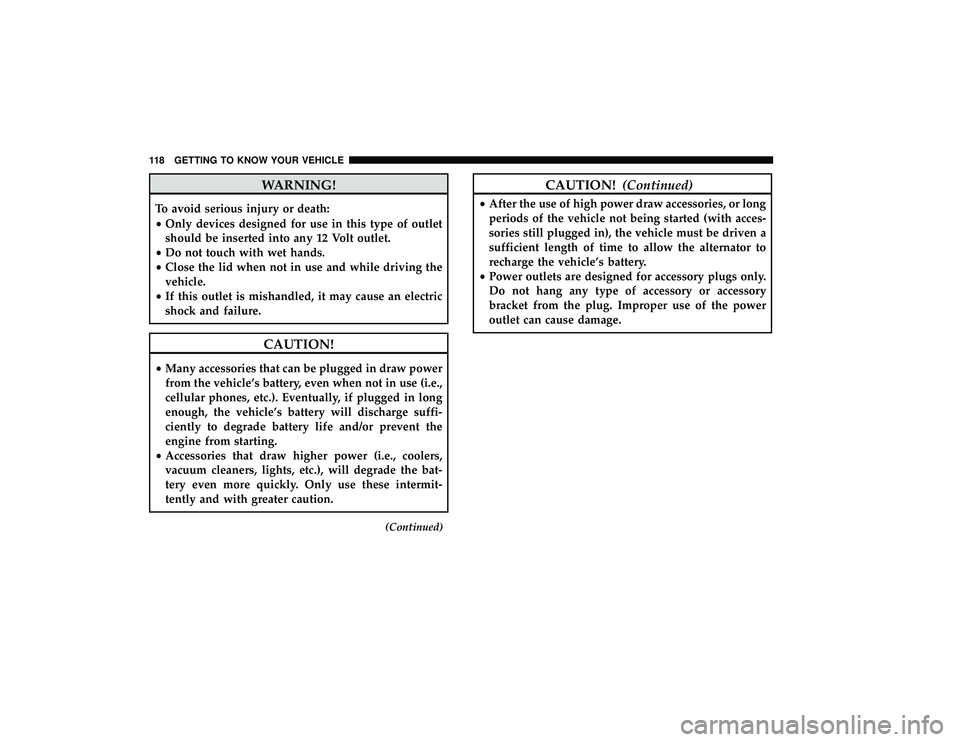
WARNING!
To avoid serious injury or death:
•Only devices designed for use in this type of outlet
should be inserted into any 12 Volt outlet.
• Do not touch with wet hands.
• Close the lid when not in use and while driving the
vehicle.
• If this outlet is mishandled, it may cause an electric
shock and failure.
CAUTION!
• Many accessories that can be plugged in draw power
from the vehicle’s battery, even when not in use (i.e.,
cellular phones, etc.). Eventually, if plugged in long
enough, the vehicle’s battery will discharge suffi-
ciently to degrade battery life and/or prevent the
engine from starting.
• Accessories that draw higher power (i.e., coolers,
vacuum cleaners, lights, etc.), will degrade the bat-
tery even more quickly. Only use these intermit-
tently and with greater caution.
(Continued)
CAUTION! (Continued)
•After the use of high power draw accessories, or long
periods of the vehicle not being started (with acces-
sories still plugged in), the vehicle must be driven a
sufficient length of time to allow the alternator to
recharge the vehicle’s battery.
• Power outlets are designed for accessory plugs only.
Do not hang any type of accessory or accessory
bracket from the plug. Improper use of the power
outlet can cause damage.
118 GETTING TO KNOW YOUR VEHICLE
Page 148 of 490

Vehicles equipped with the Anti-Lock Brake System (ABS)
are also equipped with Electronic Brake Force Distribution
(EBD). In the event of an EBD failure, the Brake Warning
Light will turn on along with the ABS Light. Immediate
repair to the ABS system is required.
Operation of the Brake Warning Light can be checked by
turning the ignition switch from the OFF position to the
ON/RUN position. The light should illuminate for ap-
proximately two seconds. The light should then turn off
unless the parking brake is applied or a brake fault is
detected. If the light does not illuminate, have the light
inspected by an authorized dealer.
The light also will turn on when the parking brake is
applied with the ignition switch in the ON/RUN position.
NOTE:This light shows only that the parking brake is
applied. It does not show the degree of brake application.
— Battery Charge Warning Light
This warning light will illuminate when the battery is not
charging properly. If it stays on while the engine is run-
ning, there may be a malfunction with the charging system.
Contact an authorized dealer as soon as possible.
This indicates a possible problem with the electrical system
or a related component.
— Door Open Warning Light — If Equipped
This indicator will illuminate when a door is ajar/open and
not fully closed.
NOTE: If the vehicle is moving, there will also be a single
chime.
— Electronic Throttle Control (ETC) Warning
Light
This warning light will illuminate to indicate a problem
with the Electronic Throttle Control (ETC) system. If a
problem is detected while the vehicle is running, the light
will either stay on or flash depending on the nature of the
problem. Cycle the ignition when the vehicle is safely and
completely stopped and the transmission is placed in the
PARK position. The light should turn off. If the light
remains on with the vehicle running, your vehicle will
usually be drivable; however, see an authorized dealer for
service as soon as possible.
NOTE: This light may turn on if the accelerator and brake
pedals are pressed at the same time.
If the light continues to flash when the vehicle is running,
immediate service is required and you may experience
reduced performance, an elevated/rough idle, or engine
stall and your vehicle may require towing. The light will
146 GETTING TO KNOW YOUR INSTRUMENT PANEL
Page 156 of 490

Onboard Diagnostic System (OBD II) Cybersecurity
Your vehicle is required to have an Onboard Diagnostic
system (OBD II) and a connection port to allow access to
information related to the performance of your emissions
controls. Authorized service technicians may need to ac-
cess this information to assist with the diagnosis and
service of your vehicle and emissions system.
WARNING!
•ONLY an authorized service technician should con-
nect equipment to the OBD II connection port in
order to read the VIN, diagnose, or service your
vehicle.
• If unauthorized equipment is connected to the OBD
II connection port, such as a driver-behavior tracking
device, it may:
• Be possible that vehicle systems, including safety
related systems, could be impaired or a loss of
vehicle control could occur that may result in an
accident involving serious injury or death.
• Access, or allow others to access, information
stored in your vehicle systems, including personal
information. For further information, refer to “Cybersecurity” in “Mul-
timedia”.
EMISSIONS INSPECTION AND MAINTENANCE
PROGRAMS
In some localities, it may be a legal requirement to pass an
inspection of your vehicle’s emissions control system.
Failure to pass could prevent vehicle registration.
For states that require an Inspection and Main-
tenance (I/M), this check verifies the “Malfunc-
tion Indicator Light (MIL)” is functioning and is
not on when the engine is running, and that the
OBD II system is ready for testing.
Normally, the OBD II system will be ready. The OBD II
system may notbe ready if your vehicle was recently
serviced, recently had a dead battery or a battery replace-
ment. If the OBD II system should be determined not ready
for the I/M test, your vehicle may fail the test.
Your vehicle has a simple ignition actuated test, which you
can use prior to going to the test station. To check if your
vehicle’s OBD II system is ready, you must do the following:
1. Cycle the ignition switch to the ON position, but do not crank or start the engine.
154 GETTING TO KNOW YOUR INSTRUMENT PANEL