Page 123 of 232

121
Before each use
Check that the towball is correctly locked by
verifying the following points:
-
t
he green mark on the locking wheel is in line
with the green mark on the towball,
-
t
he locking wheel is in contact with the towball,
-
t
he security lock is locked and the key
removed; the locking wheel can no longer be
operated,
-
t
he towball must not be able to move in its
carrier; test by trying to shake it with your hand.
During use
Never release the locking system with
a trailer or load carrier on the towball.
Never exceed the maximum authorised
weight for the vehicle (the Gross Vehicle
Weight – GV W), the trailer, or the sum of
the two (the Gross Train Weight – GTW).
Following use
When travelling without a trailer or load on
a towbar-mounted carrier, the towball must be
removed and the protective plug inserted in
the carrier. This measure applies particularly
where the towball might obscure visibility of the
number plate or its lighting.
Fitting the towball
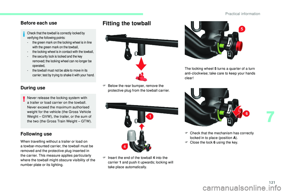
F Below the rear bumper, remove the protective plug from the towball carrier.
F
I
nsert the end of the towball 4 into the
carrier 1
and push it upwards; locking will
take place automatically. The locking wheel 5
turns a quarter of a turn
anti-clockwise; take care to keep your hands
clear!
F
C
heck that the mechanism has correctly
locked in to place (position A ).
F
C
lose the lock 6 using the key.
7
Practical information
Page 125 of 232

123
Maintenance
Correct operation is only possible if the towball
and its carrier are kept clean.
Before cleaning the vehicle with a high-
pressure jet wash, the towball must be removed
and the protective plug fitted to the carrier.
Apply the label provided to a
clearly visible
area, close to the carrier or in the boot.
Go to a
CITROËN dealer or a qualified
workshop for any work on the towbar
system.
Roof carrying systems
F Remove the towball downwards from its carrier 1 .
F
R
elease the locking wheel; this
automatically stops in the unlocked position
(position B ).
F
R
efit the protective plug to the carrier.
F
C
arefully stow the towball in its bag away
from knocks and dirt. For reasons of safety and to avoid damaging
the roof, it is essential to use a
carrying system
(roof bars or roof rack) that is approved for your
vehicle.
Roof bars can only be fitted to a
van, combi
or minibus model of height H1
or H2. On
a
minibus, check for the presence of roof air
conditioning units.
The carrying system must always be secured to
the fitting points provided on the vehicle's roof:
6, 8
or 10, depending on the wheelbase of the
vehicle.
Obser ve the instructions for fitting and use
provided with the carrying system.
7
Practical information
Page 126 of 232
124
Maximum load on the roof, evenly
distributed: 150 kg, for all models, within
the vehicle's weight limit (Gross Vehicle
Weight).
On all H3
height models, the roof cannot
be fitted with a
carrying system.
Fully comply with the legal requirements
for carrying oversized loads.
For more information on the Technical
data of your vehicle and particularly the
dimensions, refer to the corresponding
section.Changing a wiper blade
Check that the screenwash or headlamp
wash jets are not blocked.
Changing a front wiper
blade
F Raise the wiper arm.
F
U nclip the blade by pressing the button and
remove it by pulling it outwards.
F
F
it the new blade and ensure that it is
secured correctly.
F
R
eturn the wiper arm to the normal position.
The steps, located in the front bumper, enable
you to reach the blades and the screenwash
jets.
Practical information
Page 139 of 232

137
Special feature with pneumatic
suspension
If the vehicle is fitted with this system, you must
activate vehicle lifting mode before lifting the
vehicle with a jack. For vehicles with the steering wheel on the
right, the buttons are located on the right of the
steering wheel.
F
W
ith the ignition on, simultaneously press
buttons 1 and 2 for at least 5 seconds.
Their indicator lamps come on fixed.
F
T
o leave this mode, simultaneously press
buttons 1 and 2 for another 5
seconds.
Their indicator lamps go off and the system
becomes fully operational again.
This mode deactivates itself automatically if the
speed of about 3 mph (5 km/h) is exceeded.
Spare wheel
Parking
F Park the vehicle where it does not block
traffic: the ground must be level, stable and
non-slippery.
F
I
f the road is sloping or damaged, place an
object under the wheels to act as a
chock.
F
W
ith a
manual gearbox, engage first gear
then switch off the ignition to block the
wheels.
F
A
pply the parking brake and check that the
warning lamp is on in the instrument panel.
F
T
he passengers must get out of the vehicle
and wait where they are safe.
F
P
ut on the high visibility vest and signal that
the vehicle is immobile by using the devices
envisaged by the legislation in force in the
country where you are driving (warning
triangle, hazard warning lamps, etc.).
F
E
quip yourself with the tools. Once your vehicle is properly secured, you
should proceed in this order:
1-Take the tools.
2- Remove the spare wheel from its
compartment.
3- Position the jack.
4- Change the wheel to be repaired.
5- Put away the wheel to be repaired.
1 - Take the tools
These are stowed in a box located under the
f ront passenger seat.
F
T
urn the button a quarter of a turn then pull
the box.
F
A
fter use, press the button then turn it
a
quarter of a turn to secure the box.
8
In the event of a breakdown
Page 141 of 232
139
The spare wheel retaining bolt is located below
the rear bumper on the right.With steel wheels
:
With alloy wheels :
F
I
nstall the long socket A , the wheelbrace D
and the bar B on the retaining bolt.
F
T
urn the assembly anti-clockwise to lower
the wheel.
F
T
urn to the full extent, indicated by an
increase in the force required.
F
H
aving fully unwound the cable, take out the
spare wheel. F
U
nscrew the handle H.
F
R
emove the carrier I from the outer part of
the steel wheel. F
R
elease the spare wheel and place it near
the wheel to be changed.
F
I
f possible, place a chock under the
wheel diagonally opposite the wheel to be
changed.
3 - Position the jack
Ensure that the jack is stable.
If the ground is slippery or loose, the jack
may collapse – Risk of injury!
F
U
nscrew the three securing bolts K
.
F
U
nscrew the handle H
.
F
R
emove the support J from the carrier I
.
8
In the event of a breakdown
Page 143 of 232

141
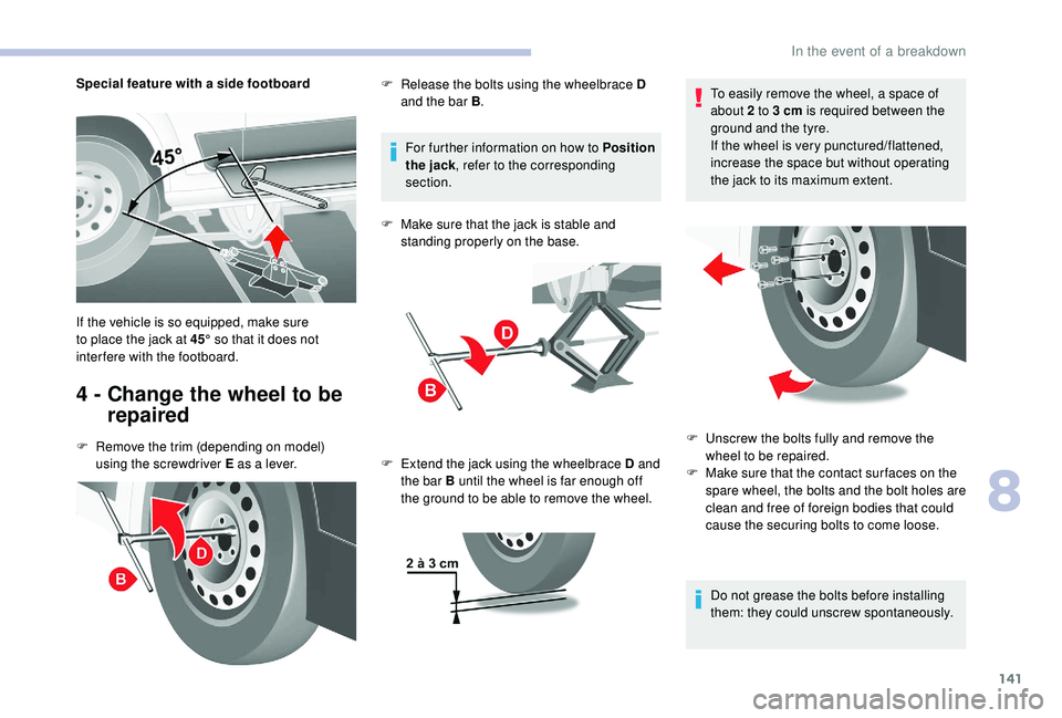
Special feature with a side footboard
4 - Change the wheel to be repaired
F Remove the trim (depending on model)
using the screwdriver E as a lever.For further information on how to Position
the jack , refer to the corresponding
section.
F
M
ake sure that the jack is stable and
standing properly on the base.
If the vehicle is so equipped, make sure
to place the jack at 45° so that it does not
interfere with the footboard. F
R
elease the bolts using the wheelbrace D
and the bar B .
F E xtend the jack using the wheelbrace D and
the bar B until the wheel is far enough off
the ground to be able to remove the wheel. To easily remove the wheel, a space of
about 2
to 3 cm is required between the
ground and the tyre.
If the wheel is very punctured/flattened,
increase the space but without operating
the jack to its maximum extent.
Do not grease the bolts before installing
them: they could unscrew spontaneously.
F
U nscrew the bolts fully and remove the
wheel to be repaired.
F
M
ake sure that the contact sur faces on the
spare wheel, the bolts and the bolt holes are
clean and free of foreign bodies that could
cause the securing bolts to come loose.
8
In the event of a breakdown
Page 144 of 232

142
Screw in the bolts in this order.
F
P
ut the spare wheel in place, making
the 2 openings M coincide with the
2 corresponding pins N
.
F
S
tart screwing in the bolts by hand.
F
P
retighten the bolts using the wheelbrace D
and the bar B .
F
L
ower the vehicle using the wheelbrace D
and the bar B , then remove the jack.
F
T
ighten the bolts again using the
wheelbrace D and the bar B .If your vehicle has tyre under-inflation
detection, check the tyre pressures and
reinitialise the system.
5 - Put away the wheel to be
repaired
You must always place the wheel to be repaired
or the spare wheel under the vehicle to secure
the carrier system.
Check that it is properly secured in its
compartment below the floor.
If the wheel is not correctly in position, it
could be dangerous.
F
R
eplace the wheel at the rear of the vehicle.
Have the tightness of the bolts and the
pressure of the spare wheel checked by
a
member of the dealer network or a qualified
workshop without delay.
Have the punctured wheel repaired and
replace it on the vehicle as soon as possible.
In the event of a breakdown
Page 145 of 232

143
With steel wheels:
With alloy wheels :
For more information on Identification
markings, including in particular the tyre
pressure label, refer to the corresponding
section.
F
H
ook the carrier I to the outer part.
F
S
crew in the handle H to secure the carrier
and steel wheel.
F
P
osition the support J on the carrier I .
F
T
ighten the handle H .
F
T
ighten the three fixing bolts K of the carrier
I onto the alloy wheel. F
I
nstall the long socket A, the wheelbrace D
and the bar B on the retaining bolt.
F
T
urn the assembly clockwise to fully draw
in the cable and raise the wheel under the
vehicle.
F
C
heck that the wheel is positioned
horizontally flat against the floor of the
vehicle and that the cut-out for the carrier
system is visible.
F
S
tow the tools and the trim (depending on
model).Changing a bulb
The headlamps have polycarbonate
lenses with a
protective coating:
F
d
o not clean them using a dr y or
abrasive cloth, nor with a
detergent
or solvent product,
F
u
se a sponge and soapy water or a pH
neutral product,
F
w
hen using a high pressure washer
on persistent marks, do not keep the
lance directed towards the lamps or
their edges for too long, so as not to
damage their protective coating and
seals.
Changing a
bulb must only be done with
the ignition off and after the headlamp has
been switched off for several minutes –
Risk of serious burns!
F
D
o not touch the bulb directly with your
fingers, use a
lint-free cloth.
It is essential only to use anti-ultraviolet
(UV) type bulbs, so as not to damage the
headlamp.
Always replace a
failed bulb with a new
bulb with the same type and specification.
8
In the event of a breakdown