Page 3 of 232

Welcome
Thank you for choosing a Citroën Jumper – Relay.
T his document presents the information and recommendations required
for you to be able to explore your vehicle in complete safety.
Your vehicle will be fitted with only some of the equipment described in
this document, depending on its trim level, model and the specification
for the country in which it was sold.
The descriptions and illustrations are given without any obligation.
Automobiles CITROËN reser ves the right to modify the technical
specifications, equipment and accessories without having to update this
edition of the guide.
If ownership of your vehicle is transferred, please ensure this Complete
Handbook is passed on to the new owner.
In this document, you will find all of the instructions and
recommendations on use that will allow you to enjoy your vehicle to the
fullest. It is strongly recommended that you familiarise yourself with it,
as well as the Maintenance and Warranty Guide which will provide you
with information about warranties, servicing and roadside assistance
associated with your vehicle. Key
Safety warning
Additional information Contributes to the protection of the environment
Left-hand drive vehicle
Right-hand drive vehicle
Key
This key will enable you to identify the special features of your vehicle: Van
Double cab
Crew cab
Chassis cab Floor cab
Tipper
Combi, minibus
Page 151 of 232

149
Third brake lamp
Ty p e A, W5W – 5W (x 4)
F
R
emove the two lamp fixing screws.
F
R
emove the lamp by pulling it towards you.
F
R
emove the bulb holder by squeezing the
two tongues inwards.
F
R
emove the failed bulb by pulling it out.
F
C
hange the bulb.
Changing a fuse
The three fuseboxes are located on the
dashboard on the left-hand side, in the pillar
on the right-hand side and in the engine
compartment.
The designations provided are only for the
fuses that can be replaced by the user. For
any other work, visit a
CITROËN dealer or
a
qualified workshop. Professional repairers: for full information
on the fuses and relays, consult the
wiring information and diagrams via the
CITROËN dealer network.
Removing and fitting a fuse
CITROËN accepts no responsibility for the
cost incurred in repairing your vehicle or
for rectifying malfunctions resulting from
the installation of accessories not supplied
by and not recommended by CITROËN
and not installed in accordance with its
specifications, in particular when the
combined power consumption of all of the
additional equipment connected exceeds
10
milliamperes.Good
Failed
Before changing a fuse, the cause of the fault
must be found and rectified. The numbers of
the fuses are indicated on the fusebox.
Always replace a faulty fuse with a fuse of
the same rating.
8
In the event of a breakdown
Page 152 of 232

150
Dashboard, left-hand side,
fuses
F Remove the bolts and tilt the box to access the fuses. Fuses A (amps)
Allocation
12 7. 5Right-hand dipped headlamp
13 7. 5Left-hand dipped headlamp
31 5Engine compartment control unit relay – Dashboard control unit
relay (ignition +)
32 7. 5Cabin lighting (battery +)
33 7. 5Battery check sensor on Stop & Start model (battery +)
34 7. 5Minibus interior lighting – Hazard warning lamps
36 10Audio system – Air conditioning controls – Alarm – Tachograph
–
Battery cut-off control unit – Additional heating programmer
(battery
+)
37 7. 5Brake lamps switch – Third brake lamp – Instrument panel (ignition +)
38 20Central door locking (battery +)
42 5ABS control unit and sensor – ASR sensor – DSC sensor – Brake
lamps switch
43 20Windscreen wiper motor (ignition +)
47 20Driver's electric window motor
48 20Passenger's electric window motor
49 5Parking sensors control unit – Audio system – Steering wheel
mounted controls – Centre and side switch panels – Auxiliary switch
panel – Battery cut-off control unit (ignition +)
50 7. 5Airbags and pre-tensioners control unit
51 5Tachograph – Power steering control unit – Air conditioning –
Reversing lamps – Water in Diesel sensor – Air flow sensor
(ignition +)
53 7. 5Instrument panel (battery +)
89 -Not used
90 7. 5Left-hand main beam
91 7. 5Right-hand main beam
92 7. 5Left-hand front foglamp
93 7. 5Right-hand front foglamp
In the event of a breakdown
Page 186 of 232

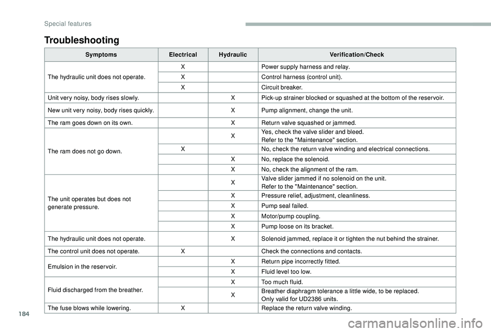
184
Troubleshooting
SymptomsElectricalHydraulic Verification/Check
The hydraulic unit does not operate. X
Power supply harness and relay.
X Control harness (control unit).
X Circuit breaker.
Unit very noisy, body rises slowly. X Pick-up strainer blocked or squashed at the bottom of the reser voir.
New unit very noisy, body rises quickly. X Pump alignment, change the unit.
The ram goes down on its own. X Return valve squashed or jammed.
The ram does not go down. X
Yes, check the valve slider and bleed.
Refer to the "Maintenance" section.
X No, check the return valve winding and electrical connections.
X No, replace the solenoid.
X No, check the alignment of the ram.
The unit operates but does not
generate pressure. X
Valve slider jammed if no solenoid on the unit.
Refer to the "Maintenance" section.
X Pressure relief, adjustment, cleanliness.
X Pump seal failed.
X Motor/pump coupling.
X Pump loose on its bracket.
The hydraulic unit does not operate. X Solenoid jammed, replace it or tighten the nut behind the strainer.
The control unit does not operate. XCheck the connections and contacts.
Emulsion in the reser voir. X
Return pipe incorrectly fitted.
X Fluid level too low.
Fluid discharged from the breather. X Too much fluid.
X
Breather diaphragm tolerance a
little wide, to be replaced.
Only valid for UD2386
units.
The fuse blows while lowering. XReplace the return valve winding.
Special features