Page 177 of 244

175
In the event of a breakdown08
Spare wheel
Visit this link to view explanatory videos:
http://q-r.to/bagGl9
For more information on the Tool kit, refer
to the corresponding section.
Accessing the spare wheel
The spare wheel is stored in the boot, under the
floor.
To access the spare wheel, first refer to the Tool
kit section.
Depending on version, the spare wheel
may be a standard size steel or alloy
wheel.
In some countries, it is a ‘space saver’ wheel.
Removing the spare wheel
► Slacken the central nut.
► Remove the fastening device (nut and bolt).
► Lift the spare wheel towards the back of the
boot.
► Take the wheel out of the boot.
Putting the spare wheel back in place
► Put the spare wheel back in place in its
housing.
► Slacken the nut on the bolt by a few turns.
► Position the fastening device (nut and bolt) in
the middle of the wheel.
► Tighten the central nut sufficiently to retain
the wheel correctly.
► Put the tool box back in place in the middle of
the wheel and clip it in place.
Removing a wheel
Parking the vehicle
Immobilise the vehicle where it does not
obstruct traffic: the ground must be level,
stable and non-slippery.
Select mode P on the automatic gearbox to
lock the wheels, apply the parking brake,
unless it is set to automatic mode, and switch
off the ignition.
Page 178 of 244

176
In the event of a breakdown08
Check that the parking brake indicator lamps
on the instrument panel are on fixed.
The occupants must get out of the vehicle and
wait where they are safe.
If necessary, place a chock under the wheel
diagonally opposite the wheel to be changed.
Never go underneath a vehicle raised using a
jack; use an axle stand.
Wheel with wheel trim
When removing the wheel, first remove
the wheel trim by pulling at the valve aperture
using the wheelbrace.
When refitting the wheel, refit the wheel trim,
starting by placing its aperture in line with the
valve and then pushing it into place all round
its edge with the palm of your hand.
► To remove the wheel bolt cover on each of the
bolts, use tool 7 (alloy wheels).
► Fit security socket 2 on wheelbrace 5 to
slacken the security bolt.
► Slacken the other bolts using the
wheelbrace 5 only.
Never use an impact wrench on the
security bolt socket.
► Place the foot of jack 6 on the ground and
ensure that it is directly below the front A or
rear B jacking point on the underbody, whichever
is closest to the wheel to be changed.
► Extend jack 6 until its head comes into contact
with jacking point A or B; contact area A or B on
the vehicle must be properly inserted into the
central part of the head of the jack.
► Raise the vehicle until there is sufficient space
between the wheel and the ground to easily admit
the spare (not punctured) wheel.
Ensure that the jack is stable. If the
ground is slippery or loose, the jack may
slip or collapse - risk of injury!
Take care to position the jack strictly at
one of the jacking points A or B under the
vehicle, ensuring that the head of the jack is
centred under the contact area on the vehicle.
Otherwise, there is a risk of damage to the
vehicle and/or of the jack collapsing - risk of
injury!
Page 179 of 244

177
In the event of a breakdown08
► Remove the bolts and store them in a clean
place.
► Remove the wheel.
Fitting a wheel
Fitting a steel or "space-saver" type spare
wheel
If the vehicle is fitted with alloy wheels, the
washers A do not make contact with the steel
or "space-saver" type spare wheel. The wheel
is held in place by the conical contact surface
B of each bolt.
► Fit the wheel on the hub.
► Screw in the bolts by hand as far as possible.
► Pre-tighten the security bolt using the
wheelbrace 5 equipped with a security socket 2.
► Pre-tighten the other bolts using the
wheelbrace 5 only.
► Lower the vehicle again fully.
► Fold jack 6 and remove it.
► Tighten the security bolt using the
wheelbrace 5 equipped with a security socket 2.
► Tighten the other bolts using the wheelbrace 5
only.
► Refit the bolt covers to each of the bolts
(depending on equipment).
► Store the tools.
After changing a wheel
Store the punctured wheel in the boot or,
depending on version, remove the central cover
first to store it beneath the floor in place of the
spare wheel.
With a "space-saver" type spare wheel
Deactivate certain driving aid functions (Active
Safety Brake, Adaptive cruise control, etc.).
Page 180 of 244

178
In the event of a breakdown08
Do not exceed the maximum authorised speed
of 50 mph (80 km/h) or the maximum distance
of 50 miles (80 km).
Driving with more than one "space-saver" type
spare wheel is prohibited.
Visit a dealer or a qualified workshop.
Have the tightening of the spare wheel's
bolts and its tyre pressure checked.
Have the punctured tyre examined. After
inspection, the technician will advise you on
whether the tyre can be repaired or if it must
be replaced.
Changing a bulb
In some weather conditions (e.g. low
temperature or humidity), misting on the
internal surface of the glass of the headlamps
and rear lamps is normal, and will disappear
after the lamps have been on for a few
minutes.
Never look too closely at the light beam of
LED technology lamps - risk of serious eye
injury!
The headlamps have polycarbonate
lenses with a protective coating:
–
Do not clean them with a dry or abrasiv
e
cloth, nor with detergent or solvent products.
–
U
se a sponge and soapy water or a pH
neutral product.
–
When using a high-pre
ssure washer on
persistent marks, do not keep the lance
directed towards the headlamps, lamps or
their edges for too long, so as not to damage
their protective coating and seals.
Changing a bulb must only be done with
the ignition off and after the headlamp /
lamp has been switched off for several
minutes - risk of serious burns!
Do not touch the bulb directly with your
fingers; use a lint-free cloth.
It is essential only to use anti-ultraviolet (UV)
type bulbs, so as not to damage the headlamp.
Always replace a failed bulb with a new bulb
of the same type and specification. To avoid
lighting imbalance, replace the bulbs in pairs.
After changing a bulb
To refit, carry out the operations in
reverse order to removal.
Close the protective cover very carefully to
guarantee the sealing of the lamps.
Light-emitting diode (LED)
headlamps and lamps
Depending on version, the affected types of
headlamps/lamps are:
–
LED t
echnology headlamps.
–
DS PIXEL LED VISION 3
.0 headlamps.
–
Offset da
ytime running lamps/sidelamps/
direction indicators.
–
Direction indic
ator side repeaters.
–
Side spo
tlamps.
–
B
rake lamps.
–
T
ailgate rear lamps.
–
Third brak
e lamp.
–
Number pla
te lamps.
If you need to replace this type of bulb,
you must contact a dealer or a qualified
workshop.
Do not touch the LED technology bulbs - risk of
electrocution!
Page 181 of 244
179
In the event of a breakdown08
Front lamps
Model with DS PIXEL LED VISION 3.0
headlamps
1. Dipped beam/main beam headlamps with
Pixel module
2. Low beam headlamps
3. Direction indicators/Daytime running lamps
4. Additional daytime running lamps/Sidelamps
(DS LIGHT VEIL)
Model with LED technology headlamps
1.Dipped beam headlamps
2. Main beam headlamps
3. Direction indicators/Daytime running lamps
4. Additional daytime running lamps/Sidelamps
(DS LIGHT VEIL)
Rear lamps
Main lamps
1.Sidelamps (LED)
2. Direction indicators (LED)
3. Brake lamps (LED)
4. Reversing lamps (LED)
Secondary lamp cluster
5.Brake lamps/sidelamps reminder (P21/5W)
6. Direction indicators reminder (PY21W)
7. Foglamps (W16W)
Access to the secondary lamp cluster
Tools required: rear protective cover opening tool
(tool kit) and Torx T30 screwdriver (not supplied).
Page 182 of 244

180
In the event of a breakdown08
► Using the opening tool, unclip the cover of
the access flap on the rear screw thread of the
towing eye, then pull it towards you.
► Insert the screwdriver head diagonally in the
cylindrical guide until you reach the lamp unit
fixing bolt.
► Slacken the bolt by about 10 turns then pull
the lamp unit to release it from the bumper.
► Disconnect the harness.
For each lamp:
► Turn the bulb holder a quarter turn anti-
clockwise and remove it.
► Remove the bulb and replace it.
Fuses
Changing a fuse
All work must be carried out only by a
dealer or a qualified workshop.
The replacement of a fuse by a third party
could cause a serious malfunction of the
vehicle.
Installing electrical accessories
The vehicle's electrical system is
designed to operate with standard or optional
equipment.
Before fitting other electrical equipment or
accessories to your vehicle, contact a dealer or
a qualified workshop.
The Manufacturer accepts no
responsibility for the cost incurred in
repairing the vehicle or for rectifying
malfunctions resulting from the installation of
accessories not supplied or not approved by it
and not installed in accordance with its
specifications, in particular when the
combined power consumption of all of the
additional equipment connected exceeds 10
milliamperes.
Page 183 of 244

181
In the event of a breakdown08
12 V battery/Accessory
batteries
Lead-acid starter batteries
These batteries contain harmful
substances (sulphuric acid and lead).
They must be disposed of in accordance
with regulations and must never under any
circumstances be discarded with household
waste.
Dispose of used batteries at a designated
collection point.
Protect your eyes and face before
handling the battery.
All operations on the battery must be carried
out in a well ventilated area and away from
naked flames and sources of sparks, to avoid
any risk of explosion or fire.
Wash your hands afterwards.
Electronic control units/LED technology
headlamps
Never connect the negative jump lead to the
metal part of the electronic control units or at
the back of the headlamps.
Risk of destroying the electronic control units
and/or headlamps!
Connect to the remote earth point provided for
this purpose.
Frozen battery
Never try to charge a frozen battery - risk
of explosion!
If the battery has frozen, have it checked by
a dealer or by a qualified workshop, who will
verify that the internal components have not
been damaged and that the case has not
cracked, which could lead to a risk of leakage
of toxic and corrosive acid.
Never try to start the engine by pushing
the vehicle.
Symbols
No sparks or naked flames, no smoking.
Always protect your eyes. Explosive gases
can cause blindness and injury.
Keep the vehicle's battery out of the reach
of children.
The vehicle's battery contains sulphuric
acid which can make you go blind or cause
severe burns.
For more information, refer to the
handbook.
Explosive gases can be present close to
the battery.
With petrol/Diesel engines
Procedure for starting the engine using another
battery or for charging a discharged battery.
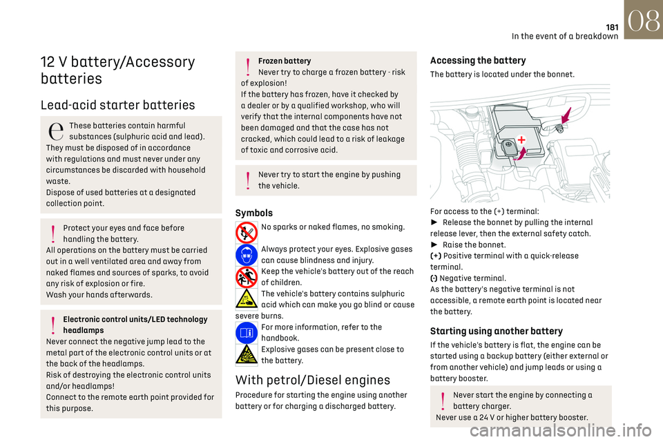
Accessing the battery
The battery is located under the bonnet.
For access to the (+) terminal:
► Release the bonnet by pulling the internal
release lever, then the external safety catch.
► Raise the bonnet.
(+) Positive terminal with a quick-release
terminal.
(-) Negative terminal.
As the battery's negative terminal is not
accessible, a remote earth point is located near
the battery.
Starting using another battery
If the vehicle's battery is flat, the engine can be
started using a backup battery (either external or
from another vehicle) and jump leads or using a
battery booster.
Never start the engine by connecting a
battery charger.
Never use a 24 V or higher battery booster.
Page 184 of 244

182
In the event of a breakdown08
Check beforehand that the backup battery has
a nominal voltage of 12 V and a capacity at
least equal to that of the discharged battery.
The two vehicles must not be in contact with
each other.
Switch off all electricity-consuming equipment
on both vehicles (audio system, wipers,
lighting, etc.).
Make sure that the jump leads are well away
from the engine’s moving parts (fan, belt, etc.).
Do not disconnect the (+) terminal while the
engine is running.
► Lift the plastic cover on the (+) terminal, if the
vehicle has one.
► Connect the red cable to the (+) terminal of
flat battery A (at the metal elbow), then to the (+)
terminal of the backup battery B or of the booster.
► Connect one end of the green or black cable
to the (-) terminal of the backup battery B or of
the booster (or to an earth point on the assisting
vehicle).
► Connect the other end of the green or black
cable to the earth point C.
► Start the engine on the assisting vehicle and
leave it running for a few minutes.
► Operate the starter on the broken down
vehicle and let the engine run.
If the engine does not start immediately, switch
off the ignition and wait a few moments before
trying again.
► Wait for it to return to idle.
► Disconnect the jump leads in reverse order.
► Refit the plastic cover to the (+) terminal, if
the vehicle has one.
► Allow the engine to run for at least 30 minutes,
with the vehicle stationary, so that the battery
reaches an adequate state of charge.
Driving immediately without having
reached a sufficient level of charge may
affect some of the vehicle's functions (e.g.
Stop & Start).
Charging the battery using a battery
charger
For optimum service life of the battery, it is
essential to maintain an adequate state of
charge.
In some circumstances, it may be necessary to
charge the battery:
–
When using the v
ehicle mainly for short
journeys.
–
If the v
ehicle is to be taken off the road for
several weeks.
Contact a dealer or a qualified workshop.
To charge the vehicle's battery yourself,
use only a charger compatible with
lead-acid batteries with a nominal voltage of
12 V.
Follow the instructions provided by the
manufacturer of the charger.
Never reverse polarities.
It is not necessary to disconnect the
battery.
► Switch the ignition off.
► Switch off all electrical consumers (audio
system, lighting, wipers, etc.).
► Switch off charger B before connecting
the cables to the battery, so as to avoid any
dangerous sparks.
► Ensure that the charger cables are in good
condition.