2019 AUDI TT ROADSTER transmission
[x] Cancel search: transmissionPage 116 of 304

Telephone
@) Note
Applicable to Canada
In Canada, operation of a Zone Enhancer,
such as an Audi Phone Box, is subject to the
following requirements of the Innovation,
Science and Economic Development Canada
(ISED):
— This is a CONSUMER device.
— BEFORE USE, you MUST meet all require-
ments set out in CPC-2-1-05.
— You MUST operate this device with approved
antennas
and cables as specified by the
manufacturer. Antennas MUST NOT be in-
stalled within 20 cm of any person.
— You MUST cease operating this device im-
mediately if requested by ISED or a licensed
wireless service provider.
— WARNING: £911 location information may
not be provided or may be inaccurate for
calls served by using this device.
G) Tips
— The Audi phone box is not available in all
countries. For additional information, con-
tact an authorized Audi dealership.
— Placing the mobile device in a bag or protec-
tive sleeve inside the Audi phone box can in-
terfere with the connection to the external
antenna.
— Metal objects cannot be located in the Audi
phone box when using the exterior antenna*
and the Audi phone box charging function.
— The charging time and temperature will vary
depending on the mobile device being used.
— When the ignition is switched on, you can
charge your mobile device in the Audi phone
box.
—To reduce the risk of malfunctions, make
sure the mobile device is positioned correct-
ly in the Audi phone box.
— The maximum charging output is 5 watts.
— Strong transmission quality cannot be guar-
anteed if more than one mobile device is in
the box.
— Audi recommends using Audi Genuine Ac-
cessories. Audi has verified their reliability,
safety, and suitability.
114
— You can purchase a USB adapter from an au-
thorized Audi dealer or authorized Audi
Service Facility, or at specialty stores.
— If you place your remote control key togeth-
er with your mobile device in the Audi phone
box, it may cause your mobile device to stop
charging if wireless charging is active.
Using the telephone
Opening the telephone
Applies to: vehicles with telephone
Call list
(2 Sa
©— Directory
(4)o 4) Es yor Llane
(=) Tekt message (mobile device)
Sy
Fig. 111 Example: telephone functions in selection menu
Hy ee al dg
5 Text message (myPhone)
|i] Text message (Additional phone)
@—= E-mail (myPhone)
Fig. 112 Example: additional telephone functions in selec-
tion menu
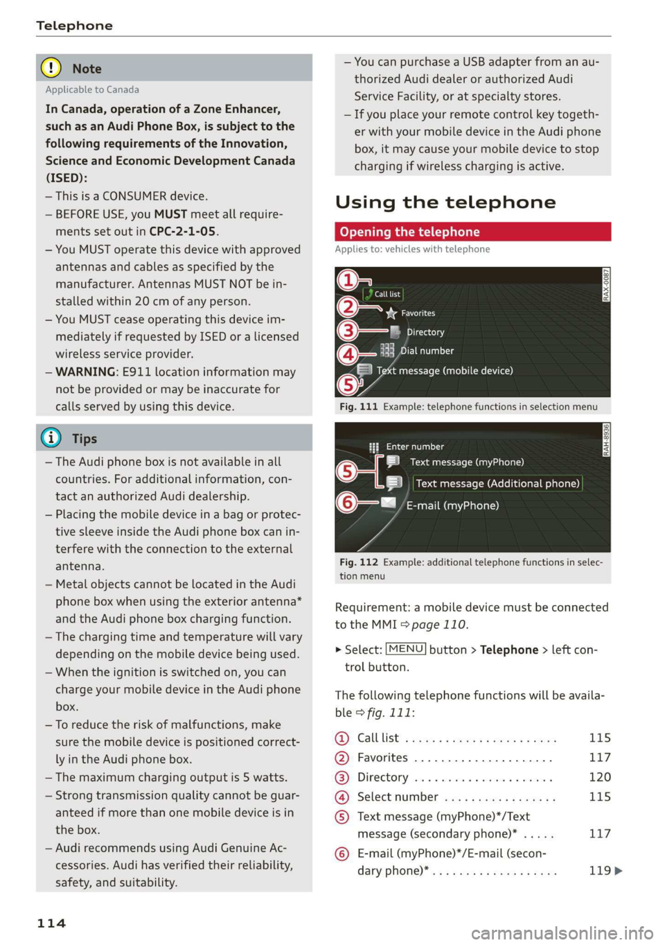
Requirement: a mobile device must be connected
to the MMI > page 110.
> Select: [MENU] button > Telephone > left con-
trol button.
The following telephone functions will be availa-
ble > fig. 111:
@): Calllist: : soy. sc cease 4: ews yo ewe 115
@ Favorites ................20.0, 117
@® Directory ....... 0. cece eee eee 120
@ Select number ...............0. 115
© Text message (myPhone)*/Text
message (secondary phone)* ..... 117
© E-mail (myPhone)*/E-mail (secon-
dary: phone) * ws « een ss wawn se eee 119>
Page 131 of 304

8S8012721BA
Audi connect
License subscription
The validity and expiration date of your licenses
are displayed.
Refresh
The content of the selected Audi connect Info-
tainment service or the entire Audi connect Info-
tainment list is updated.
Data privacy
Requirement: the ignition must be switched on.
Location, vehicle, and personal data are transmit-
ted when using Audi connect services.
Allowing sending of data
— Select and confirm Activate data connection.
The data module for the use of all Audi connect
services will be active.
Restricting sending of data
— Select and confirm Activate privacy. The data
connection is limited or deactivated depending
on the equipment. The majority of Audi connect
services will not be available.
The following interfaces are not affected by this
setting: Bluetooth, Bluetooth Low Energy (BLE),
Wi-Fi connection, Audi smartphone interface
(ASI), Near Field Communication (NFC), charging
communication (e-tron), Electronic Toll Collect
(ETC), if equipped.
® Note
Always follow the information found in >@ in
General information on page 125.
G) Tips
If the transmission of data is limited, data
will still be transmitted to verify subscrip-
tions.
Settings
Cell phone network
> Select: [MENU] button > Audi connect > right
control button > Connection manager.
> Select: right control button > Online settings >
Data connection settings.
Depending on the country, vehicle equipment,
and connection type, the following functions may
be available:
Data connection settings
Using the Data connection settings menu, you
can set when the system should connect to the
Internet. The Internet connection disconnects
automatically once the requested Audi connect
Infotainment service no longer requires any data.
— Connection setup: you can select when a data
connection should be established.
— Audi connect (MMI): when this function is
switched on, a data connection is automatically
established in order to use Audi connect Info-
tainment services.
— Wi-Fi devices: when this function is switched
on, you can allow or deny Internet connections.
Connection settings
The connection is configured automatically based
on the SIM card being used. The following values
can be changed. You can obtain more information
from your cell phone service provider.
— APN: the access point depends on the cell
phone service provider and is assigned auto-
matically.
— User name: your cell phone service provider as-
signs the user name for your online profile.
— Password: your cell phone service provider as-
signs the password for your online profile.
ZA WARNING
Always follow the information found in > A\
in General information on page 125.
@) Note
Always follow the information found in >@ in
General information on page 125.
(i) Tips
For more information on roaming charges,
contact your cell phone service provider.
129
Page 229 of 304

8S58012721BA
Checking and Filling
Emissions control
system
General information
ZA WARNING
The temperature of the exhaust system is
high, both when driving and after stopping
the engine.
— Never touch the exhaust tail pipes once they
have
become hot. This could result in burns.
— Do not park your vehicle over flammable
materials such as grass or leaves because
the high temperature of the emissions sys-
tem could start a fire.
— Do not apply underbody protectant in the
exhaust system area, because this increases
the risk of fire.
(e)e-1 Mid (Reel Tale
Follow the safety precautions > page 227, Gener-
al information.
The vehicle may only be driven with unleaded
gasoline, or the catalytic converter will be de-
stroyed.
Never drive until the tank is completely empty.
The irregular supply of fuel that results from that
can cause engine misfires. Uncombusted fuel
could enter the exhaust system, which could
cause overheating and damage to the catalytic
converter.
On Board Diagnostic System (OBD)
The On Board Diagnostic System monitors the
engine and transmission components that influ-
ence emissions.
- 5
z é
port for the On Board Diagnostic System (OBD)
On Board Diagnostic System
Engine data can be read out at the On Board Di-
agnostic System connection port using a special
testing device > fig. 171.
Indicator light
If the S indicator light blinks or turns on, there
is a malfunction that is causing poor emissions
quality and that could damage the catalytic con-
verter. Drive slowly to an authorized Audi dealer
or authorized Audi Service Facility to have the
malfunction corrected.
Z\ WARNING
Incorrect use of the connection port for the
On Board Diagnostic System can cause mal-
functions, which can then result in accidents
and serious injuries.
— Only allow an authorized Audi dealer or au-
thorized Audi Service Facility to read out the
engine data.
Engine compartment
General information
Special care is required if you are working in the
engine compartment
For work in the engine compartment, such as
checking and filling fluids, there is a risk of in-
jury, scalding, accidents, and burns. For this
227
>
Page 244 of 304

Wheels
@ US DOT number (TIN) and
manufacture date
The manufacture date is listed on
the tire sidewall (it may only ap-
pear on the inner side of the tire):
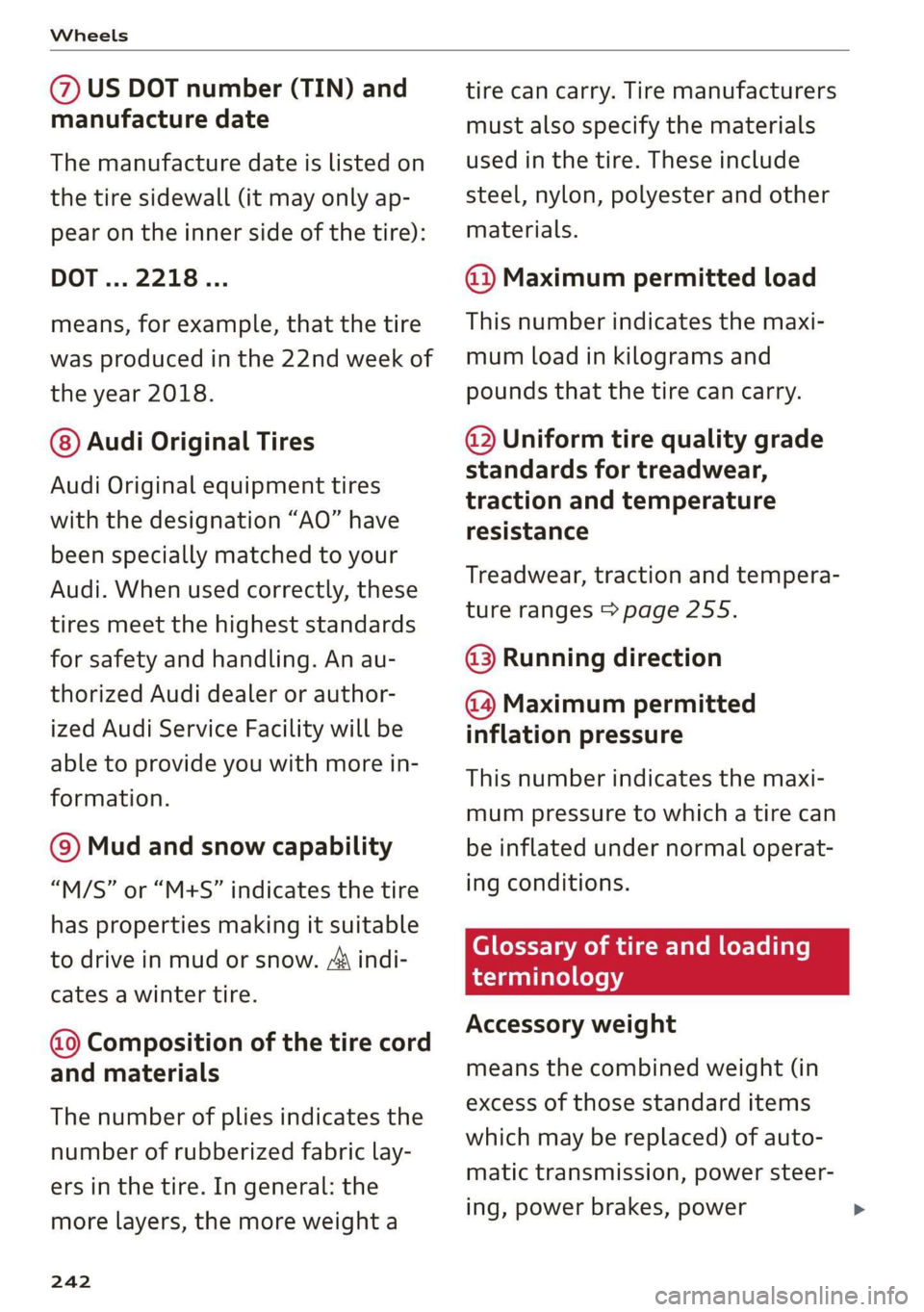
DOT... 2218...
means, for example, that the tire
was produced in the 22nd week of
the year 2018.
@) Audi Original Tires
Audi Original equipment tires
with the designation “AO” have
been specially matched to your
Audi. When used correctly, these
tires meet the highest standards
for safety and handling. An au-
thorized Audi dealer or author-
ized Audi Service Facility will be
able to provide you with more in-
formation.
@) Mud and snow capability
“M/S” or “M+S” indicates the tire
has properties making it suitable
to drive in mud or snow. /& indi-
cates a winter tire.
Composition of the tire cord
and materials
The number of plies indicates the
number of rubberized fabric lay-
ers in the tire. In general: the
more layers, the more weight a
242
tire can carry. Tire manufacturers
must also specify the materials
used in the tire. These include
steel, nylon, polyester and other
materials.
@ Maximum permitted load
This number indicates the maxi-
mum load in kilograms and
pounds that the tire can carry.
@ Uniform tire quality grade
standards for treadwear,
traction and temperature
resistance
Treadwear, traction and tempera-
ture ranges > page 255.
@ Running direction
@ Maximum permitted
inflation pressure
This number indicates the maxi-
mum pressure to which a tire can
be inflated under normal operat-
ing conditions.
Glossary of tire and loading
terminology
Accessory weight
means the combined weight (in
excess of those standard items
which may be replaced) of auto-
matic transmission, power steer-
ing, power brakes, power
Page 276 of 304

Emergency assistance
> The wheel bolt tightening specification must be
90 ft lbs (120 Nm). Have it checked as soon as
possible with a torque wrench. Drive carefully
until then.
> Have the faulty wheel replaced as quickly as
possible.
Spare tire
General information
Applies to: vehicles with space-saving spare tire (compact
spare tire)
—maa
BFV-0166
The spare tire is intended for short-term use only.
Have the damaged tire checked and replaced if
necessary by an authorized Audi dealer or author-
ized Audi Service Facility as soon as possible.
There are some restrictions on the use of the
compact spare tire. The compact spare tire has
been designed specifically for your type of vehi-
cle. Do not replace it with the spare tire from an-
other type of vehicle.
Removing the spare tire
> Turn the handle > fig. 197 @ counter-clock-
wise.
>» Remove the spare tire.
Removing the vehicle jack
> Lift up the cover on the right side of the lug-
gage compartment and remove the vehicle
jack.
Snow chains
For technical reasons, the use of snow chains on
the
compact spare tire is not permitted.
If you have to drive with snow chains and a front
tire fails, mount the spare tire in place of a rear
274
tire. Install the snow chains on the rear tire that
you removed, and install that in place of the
front tire that failed.
Z\ WARNING
— After installing a spare tire, the tire pressure
must be checked as soon as possible.
— Do not drive faster than SO mph (80 km/h)
with a compact spare tire. Driving faster
than that increases the risk of an accident.
— To reduce the risk of an accident, avoid hard
acceleration or braking and driving fast
around curves with the compact spare tire.
— To reduce the risk of an accident, never drive
with more than one compact spare tire.
— Normal summer or winter tires must not be
mounted on the compact spare wheel rim.
Towing
General information
You should only perform the steps that follow if
you have the necessary tools and technical ex-
pertise.
Towing requires a certain amount of practice. Au-
di recommends contacting a towing company to
have the vehicle transported.
You should only have your vehicle towed by an-
other vehicle when disabled in exceptional cir-
cumstances. Inexperienced drivers should not
tow.
Notes on towing
When the engine is stopped, the transmission
will not be sufficiently lubricated if traveling at
high speeds and long distances:
— The maximum permitted towing speed is 30
mph (50 km/h).
— The maximum permitted towing distance is 30
miles (50 km).
Additional information on towing with a tow
truck
The vehicle may only be towed with the front axle
raised. Do not wrap any chains or cables around
the brake lines.
Page 277 of 304

8S8012721BA
Emergency assistance
If the vehicle should be towed with the axle
raised, then the ignition must be switched off to
reduce the risk of damage to the drivetrain.
Tow bar and towing cable
The vehicle can be towed with a tow bar or tow-
ing cable. Both drivers should be familiar with
the special considerations when towing, especial-
ly when using a towing cable.
Always make sure the traction force does not ex-
ceed the permitted level and there are no shock
loading conditions. There is always the risk of the
coupling becoming overloaded when driving off-
road.
For the most safety and security, drive with a tow
bar. You should use a towing cable only if a tow
bar is not available. Use a towing cable made of
synthetic elastic cable similar elastic material.
ZA\ WARNING
— Towing highly increases the risk of an acci-
dent, for example from colliding with the
towing vehicle.
— To reduce the risk of an accident, do not al-
low anyone to remain inside the vehicle
when it is being transported by a tow truck
or a special transporter.
@) Note
— If normal towing is not possible, for exam-
ple if the transmission is faulty or if the
towing distance is greater than 30 miles
(50 km), then transport the vehicle on a
special carrier.
— If the vehicle is towed by a tow truck at the
axle that is not permitted, this can cause se-
vere damage to the transmission.
— The vehicle must not be tow started for
technical reasons.
@) Tips
—If there is a power failure, the selector lever
will not move out of the "P" position. The
parking lock must be released using the
D_ Requirement: the vehicle battery must have a sufficient
charge level.
emergency release before towing the vehi-
cle > page 68.
— Follow the local legal regulations for tow-
ing.
Read and follow the important information under
=> page 274.
Preparations
> Only secure the towing cable or tow bar at the
designated towing loops > page 276,
=> page 276.
> Make sure the towing cable is not twisted. Oth-
erwise it could disconnect from the towing loop
while towing.
» Switch the emergency flashers on in both vehi-
cles > page 40. However, do not do this if it
prohibited by law.
Towing vehicle (front)
> Only start to drive when the towing cable is
taut.
> Be especially careful when accelerating.
> Avoid sudden braking or driving maneuvers.
Vehicle being towed (rear)
» Make sure the ignition is switched on so that
the steering wheel is not locked and so that you
can use the turn signals, the horn, and the
windshield wipers if needed > A\.
> The brake booster only works when the engine
is running. Power steering only works when the
ignition is switched on and the vehicle is roll-
ing )). If the brake booster and power steering
are not functioning, you must press the brake
pedal much harder and use more force to steer.
> Release the parking brake > page 59.
> Select the "N" selector lever position.
> Make sure the towing cable is always taut.
275
>
Page 280 of 304
![AUDI TT ROADSTER 2019 Owners Manual Fuses and bulbs
Interior fuse assignment
ft
pl Bel Fe
» BEBE ERED
Poo
ns
[24] 25) rao) 27) Fe Ra
23 |
Fsacsomeemr STE 42)
eases eres] b
ro Wa a i ee
1F52) FOL
Re
B8V-0217
AUDI TT ROADSTER 2019 Owners Manual Fuses and bulbs
Interior fuse assignment
ft
pl Bel Fe
» BEBE ERED
Poo
ns
[24] 25) rao) 27) Fe Ra
23 |
Fsacsomeemr STE 42)
eases eres] b
ro Wa a i ee
1F52) FOL
Re
B8V-0217](/manual-img/6/57667/w960_57667-279.png)
Fuses and bulbs
Interior fuse assignment
ft
pl Bel Fe
» BEBE ERED
Poo
ns
[24] 25) rao) 27) Fe Ra
23 |
Fsacsomeemr STE 42)
eases eres] b
ro Wa a i ee
1F52) FOL
Re
B8V-0217
No. | Equipment
F20 | Power lumbar support adjustment
Front passenger's side neck heating (Road-
F22
ster)
Right vehicle electrical system control
F24
module
F25 | Driver side door
F26 | Seat heating
Vehicle electrical system control module
Fae (terminal 30)
F28 | AMI High media port
F29 | Vehicle electrical system control module
F32 | Driver assistance systems
F33 | Airbag
Sockets, interior sound, tail light switch,
F34 | temperature sensor, oil level sensor, neck
heating, garage door opener
Fig. 202 Vehicle interior: fuse assignment
No. Equipment
Diagnosis, headlight range control, air
quality sensor, automatic dimming rear-
view mirror, center instrument panel
switch module
F35
F4 Central computer processor (MIB-2) F36 | Right cornering light / right LED headlight
FS Gateway (diagnostics) F37 | Left cornering light / left LED headlight
Fo Selector lever (automatic transmission)
F7
Climate control system controls, rear win-
dow defogger, tire pressure monitoring
Engine control module, ESC control mod-
F38
ule
F39 | Front passenger side door
F8
Switch for the electromechanical parking
brake, light switch, rain/light sensor, inte-
rior lighting, diagnostic connector, roof
electronics F40
| Cigarette lighter, sockets
F41 | Fuel tank diagnosis
F42 | Central locking area
FQ Steering column switch module
F44 | All wheel drive clutch control module
F10 Vehicle positioning
F45 | Power adjustable driver's side seat
Fll
All wheel drive clutch, left vehicle electri-
cal system control module
F46 | Driver's side neck heating (Roadster)
F49 | Engine start, clutch sensor
F12 Infotainment components
F52 | Control module for suspension control
F1l4 Climate control system blower fan
F53 | Rear window defogger
Fis Electronic steering column lock
F16
Infotainment system components, safety
belt microphone
F17 Instrument cluster
F18 Rearview camera
F19
Convenience access control module
278
The power seats* are protected via circuit break-
ers that automatically switch on after a few sec-
onds after the overload has been reduced.
Page 281 of 304

8S58012721BA
Fuses and bulbs
Left engine compartment fuse assignment
B8V-0173
ment
Fig. 203 Left side of engine compartment: fuse assign-
No. Equipment
Fl ESC control module
F2 ESC control module
F3 Engine control module
F4
Engine components, engine cooling, sec-
ondary air pump
FS Engine components, tank system
Fo Brake light switch
F7 Engine components
F8 Heat oxygen sensor
F9 Engine components, exhaust door
F10 Fuel injectors, fuel control module
F13 Transmission fluid pump
F1l4 Ignition coils (5-cylinder)
Fis Horn
F16 Ignition coils
F17 Suppressor
F18
Diagnostic interface, battery monitoring,
garage door opener antenna
F19 Windshield wipers
F20
Anti-theft alarm system
No. Equipment
F21 Automatic transmission control module
F22
Terminal 50 diagnosis (engine control
module)
F23 Engine start
F31
Engine components (5-cylinder)
Bulbs
Cs
Your vehicle is equipped with maintenance-free
headlights and tail lights. However, if a light bulb
needs to be replaced, please contact an author-
ized Audi dealer or authorized Audi Service Facili-
ty.
279