Page 97 of 106

Motorcycle care and stora ge
7-3
7
trea
ds. Otherwise these parts
will become slippery, which
coul d cause loss of control.
Thorou ghly clean the surfaces
of these parts before operatin g
the vehicle.
[EWA20650]
5. Treat rubber, vinyl, and unpainted plastic parts with a suitable care
product.
6. Touch up minor paint damage caused by stones, etc.
7. Wax all painted surfaces using a non-abrasive wax or use a detail
spray for motorcycles.
8. When finished cleaning, start the engine and let it idle for several
minutes to help dry any remaining
moisture.
9. If the headlight lens has fogged up, start the engine and turn on
the headlight to help remove the
moisture.
10. Let the vehicle dry completely be- fore storing or covering it.NOTICE
ECA26320
Do not apply wax to ru bber or
unpainte d plastic parts.
Do not use a brasive polishin g
compoun ds as they will wear
away the paint.
Apply sprays an d wax sparin gly.
Wipe off excess afterwar ds.
WARNING
EWA20660
Contaminants left on the brakes or
tires can cause loss of control. Make sure there is no lu bricant
or wax on the brakes or tires.
If necessary, wash the tires with
warm water an d a mil d d eter-
g ent.
If necessary, clean the b rake
d iscs an d pa ds with b rake
cleaner or acetone.
Before ri din g at hi gher spee ds,
test the vehicle’s brakin g per-
formance an d cornerin g b ehav-
ior.
EAU83472
Stora geAlways store the vehicle in a cool, dry
place. If necessary, protect it against
dust with a porous cover. Be sure the
engine and the exhaust system are
cool before covering the vehicle. If the
vehicle often sits for weeks at a time
between uses, the use of a quality fuel
stabilizer is recommended after each
fill-up.NOTICE
ECA21170
Storin g the vehicle in a poorly
ventilate d room or coverin g it
with a tarp, while it is still wet,
will allow water an d humi dity to
seep in an d cause rust.
To prevent corrosion, avoi d
d amp cellars, stab les (because
of the presence of ammonia)
an d areas where stron g chemi-
cals are stored .Long term stora ge
Before storing the vehicle long term (60
days or more):
UBD5E0E0.book Page 3 Wednesday, April 25, 2018 2:23 PM
Page 98 of 106

Motorcycle care and stora ge
7-4
7 1. Make all necessary repairs and
perform any outstanding mainte-
nance.
2. Follow all instructions in the Care section of this chapter.
3. Fill up the fuel tank, adding fuel stabilizer according to product in-
structions. Run the engine for 5
minutes to distribute treated fuel
through the fuel system.
4. For vehicles equipped with a fuel cock: Turn the fuel cock lever to
the off position.
5. For vehicles with a carburetor: To prevent fuel deposits from build-
ing up, drain the fuel in the carbu-
retor float chamber into a clean
container. Retighten the drain bolt
and pour the fuel back into the fuel
tank.
6. Use a quality engine fogging oil according to product instructions
to protect internal engine compo-
nents from corrosion. If engine
fogging oil is not available, per-
form the following steps for each
cylinder:a. Remove the spark plug cap and spark plug. b. Pour a teaspoonful of engine
oil into the spark plug bore.
c. Install the spark plug cap onto the spark plug, and then place
the spark plug on the cylinder
head so that the electrodes are
grounded. (This will limit spark-
ing during the next step.)
d. Turn the engine over several times with the starter. (This will
coat the cylinder wall with oil.)
WARNING! To prevent d am-
a g e or injury from sparkin g,
make sure to groun d the
spark plu g electro des while
turnin g the en gine over.
[EWA10952]
e. Remove the spark plug cap
from the spark plug, and then
install the spark plug and the
spark plug cap.
7. Lubricate all control cables, piv- ots, levers and pedals, as well as
the sidestand and centerstand (if
equipped).
8. Check and correct the tire air pressure, and then lift the vehicle
so that all wheels are off the
ground. Otherwise, turn the wheels a little once a month in or-
der to prevent the tires from be-
coming degraded in one spot.
9. Cover the muffler outlet with a plastic bag to prevent moisture
from entering it.
10. Remove the battery and fully charge it, or attach a maintenance
charger to keep the battery opti-
mally charged. NOTICE: Confirm
that the battery an d its char ger
are compati ble. Do not char ge a
VRLA battery with a convention-
al char ger.
[ECA26330]
TIP If the battery will be removed,
charge it once a month and store
it in a temperate location between
0-30 °C (32-90 °F).
See page 6-29 for more informa-
tion on charging and storing the
battery.
UBD5E0E0.book Page 4 Wednesday, April 25, 2018 2:23 PM
Page 99 of 106

Overall width:
885 mm (34.8 in)
Overall height: 1250 mm (49.2 in)
Seat height: 820 mm (32.3 in)
Wheelbase:
1510 mm (59.4 in)
Ground cle")
Specifications
8-1
8
Dimensions:Overall length:2150 mm (84.6 in)
Overall width:
885 mm (34.8 in)
Overall height: 1250 mm (49.2 in)
Seat height: 820 mm (32.3 in)
Wheelbase:
1510 mm (59.4 in)
Ground clearance: 150 mm (5.91 in)
Minimum turning radius: 2.8 m (9.19 ft)Wei ght:Curb weight:
263 kg (580 lb)Engine:Combustion cycle:
4-stroke
Cooling system: Liquid cooled
Valve train: DOHC
Cylinder arrangement:
Inline
Number of cylinders: 3-cylinder
Displacement: 847 cm³
Bore × stroke:
78.0 × 59.1 mm (3.07 × 2.33 in) Starting system:
Electric starter
Engine oil:Recommended brand:
YAMALUBE
SAE viscosity grades: 10W-40
Recommended engine oil grade: API service SG type or higher, JASO
standard MA
Engine oil quantity: Oil change:2.40 L (2.54 US qt, 2.11 Imp.qt)
With oil filter removal: 2.70 L (2.85 US qt, 2.38 Imp.qt)Coolant quantity:Coolant reservoir (up to the maximum level
mark):
0.25 L (0.26 US qt, 0.22 Imp.qt)
Radiator (including all routes): 1.93 L (2.04 US qt, 1.70 Imp.qt)Fuel:Recommended fuel:
Premium unleaded gasoline (Gasohol [E10]
acceptable)
Fuel tank capacity:
18 L (4.8 US gal, 4.0 Imp.gal)
Fuel reserve amount: 4.0 L (1.06 US gal, 0.88 Imp.gal)Fuel injection:Throttle body:
ID mark:BD51 00
Drivetrain:Gear ratio:
1st:2.667 (40/15)
2nd: 2.000 (38/19)
3rd:
1.619 (34/21)
4th: 1.381 (29/21)
5th: 1.190 (25/21)
6th:
1.037 (28/27)Chassis:Track:410 mm (16.1 in)Front tire:Type:Tubeless
Size: 120/70 R 15 M/C 56V
Manufacturer/model:
BRIDGESTONE/A41F MRear tire:Type: Tubeless
Size:
190/55 R 17 M/C 75V
Manufacturer/model: BRIDGESTONE/A41R MLoa din g:Maximum load:
195 kg (430 lb)
UBD5E0E0.book Page 1 Wednesday, April 25, 2018 2:23 PM
Page 100 of 106
Specifications
8-2
8
(Total weight of rider, passenger, cargo
and accessories)
Front brake:Type:
Hydraulic disc brakeRear brake:Type:
Hydraulic single disc brakeFront suspension:Type:Telescopic forkRear suspension:Type:
Swingarm (link suspension)Electrical system:System voltage:12 VBattery:Model:YTZ10S
Voltage, capacity: 12 V, 8.6 Ah (10 HR)Bul b watta ge:Headlight:
LED
Brake/tail light: LED
Front turn signal light:
LED
Rear turn signal light: LED
Auxiliary light: LED License plate light:
LED
UBD5E0E0.book Page 2 Wednesday, April 25, 2018 2:23 PM
Page 101 of 106
Consumer information
9-1
9
EAU53562
Id entification num bersRecord the vehicle identification num-
ber, engine serial number, and the
model label information in the spaces
provided below. These identification
numbers are needed when registering
the vehicle with the authorities in your
area and when ordering spare parts
from a Yamaha dealer.
VEHICLE IDENTIFICATION NUMBER:
ENGINE SERIAL NUMBER:
MODEL LABEL INFORMATION:
EAU26411
Vehicle i dentification num ber
The vehicle identification number is
stamped into the frame.TIPThe vehicle identification number is
used to identify your vehicle and may
be used to register it with the licensing
authority in your area.
EAU26442
En gine serial num ber
The engine serial number is stamped
into the crankcase.
EAU26461
Mo del la bel
1. Vehicle identification number
1
1. Engine serial number
1. Model label
1
1
UBD5E0E0.book Page 1 Wednesday, April 25, 2018 2:23 PM
Page 102 of 106

Consumer information
9-2
9The model label is affixed to the loca-
tion shown. Record the information on
this label in the space provided. This
information will be needed when order-
ing spare parts from a Yamaha dealer.
EAU69910
Diagnostic connectorThe diagnostic connector is located as
shown.
EAU85300
Vehicle data recordingThis model’s ECU stores certain vehi-
cle data to assist in the diagnosis of
malfunctions and for research, statisti-
cal analysis and development purpos-
es.
Although the sensors and recorded
data will vary by model, the main data
points are:
Vehicle status and engine perfor-
mance data
Fuel-injection and emission-relat-
ed data
This data will be uploaded only when a
special Yamaha diagnostic tool is at-
tached to the vehicle, such as when
maintenance checks or service proce-
dures are performed.
Vehicle data uploaded will be handled
appropriately according to the follow-
ing Privacy Policy.
Privacy Policy Yamaha will not disclose this data to a
third party except in the following cas-
es. In addition, Yamaha may provide
vehicle data to a contractor in order to
outsource services related to the han-
dling of vehicle data. Even in this case,
Yamaha will require the contractor to properly handle the vehicle data we
provided and Yamaha will appropriate-
ly manage the data. With the consent of the vehicle
owner
Where obligated by law
For use by Yamaha in litigation
When the data is not related to an
individual vehicle nor owner
1. Diagnostic connector
1
https://www.yamaha-motor.eu/eu/
privacy/privacy-policy.aspx
UBD5E0E0.book Page 2 Tuesday, May 8, 2018 9:16 AM
Page 103 of 106

10-1
10
Index
AABS....................................................... 3-20
ABS warning light ................................... 3-6
Air filter element.................................... 6-15
Auxiliary DC connector ......................... 3-34
Auxiliary DC jack .................................. 3-33BBattery .................................................. 6-29
Brake and clutch levers, checking and
lubricating........................................... 6-26
Brake and shift pedals, checking and lubricating........................................... 6-26
Brake fluid, changing............................ 6-23
Brake fluid level, checking.................... 6-21
Brake lever............................................ 3-20
Brake lever free play, checking ............ 6-19
Brake light switches ............................. 6-20
Brake pedal .......................................... 3-20CCables, checking and lubricating ......... 6-25
Canister ................................................ 6-11
Care ........................................................ 7-1
Catalytic converter ............................... 3-26
Clutch lever........................................... 3-18
Clutch lever free play, adjusting ........... 6-19
Coolant ................................................. 6-13
Coolant temperature warning light ......... 3-6
Cruise control indicator lights................. 3-5
Cruise control switches .......................... 3-4
Cruise control system............................. 3-8DData recording, vehicle........................... 9-2
Diagnostic connector ............................. 9-2
Dimmer/Pass switch............................... 3-4 D-mode (drive mode) ........................... 3-18
Drive chain, cleaning and lubricating ... 6-24
Drive chain slack .................................. 6-23
Drive mode switch ................................. 3-4
EEngine break-in ...................................... 5-3
Engine idling speed, checking ............. 6-15
Engine oil.............................................. 6-11
Engine serial number ............................. 9-1
Engine trouble warning light .................. 3-6FFront and rear brake pads, checking ... 6-20
Front fork, adjusting ............................. 3-30
Front fork, checking ............................. 6-28
Fuel ...................................................... 3-24
Fuel consumption, tips for reducing ...... 5-3
Fuel tank cap........................................ 3-23
Fuel tank overflow hose ....................... 3-26
Fuses, replacing ................................... 6-31HHandlebar switches ............................... 3-3
Hazard switch ........................................ 3-4
Helmet holding cable ........................... 3-28
High beam indicator light ....................... 3-5
Horn switch ............................................ 3-4IIdentification numbers ........................... 9-1
Ignition circuit cut-off system .............. 3-35
Immobilizer system ................................ 3-1
Immobilizer system indicator light ......... 3-7
Indicator lights and warning lights ......... 3-5MMain switch/steering lock ...................... 3-2
Maintenance and lubrication, periodic... 6-5Maintenance, emission control
system .................................................. 6-3
Matte color, caution................................ 7-1
MENU switch .......................................... 3-4
Model label ............................................. 9-1
Multi-function meter unit ...................... 3-11
NNeutral indicator light ............................. 3-5OOil level warning light .............................. 3-5PPanel, removing and installing ................ 6-9
Parking.................................................... 5-4
Part locations.......................................... 2-1QQuick shift system ................................ 3-19RRear view mirrors .................................. 3-30SSafety information................................... 1-1
Seats ..................................................... 3-27
SELECT switch ....................................... 3-4
Shift indicator light .................................. 3-7
Shifting.................................................... 5-2
Shift pedal............................................. 3-19
Shock absorber assembly, adjusting ... 3-31
Sidestand.............................................. 3-34
Sidestand, checking and lubricating .... 6-27
Spark plugs, checking .......................... 6-10
Specifications ......................................... 8-1
Stability bar ........................................... 6-33
Starting the engine ................................. 5-1
Steering bearings, lubricating ............... 6-29
Steering, checking ................................ 6-28
UBD5E0E0.book Page 1 Wednesday, April 25, 2018 2:23 PM
Page 104 of 106

Index
10-2
10
Stop/Run/Start switch ............................ 3-4
Storage ................................................... 7-3
Storage compartment ........................... 3-29
Swingarm pivots, lubricating ................ 6-27TThrottle grip and cable, checking and
lubricating ........................................... 6-25
Throttle grip free play, checking ........... 6-15
Tires ...................................................... 6-16
Tool kit .................................................... 6-2
Traction control system ........................ 3-21
Traction control system indicator light ... 3-6
Troubleshooting .................................... 6-33
Troubleshooting charts ......................... 6-35
Turn signal indicator lights ...................... 3-5
Turn signal switch ................................... 3-4VValve clearance..................................... 6-16
Vehicle identification number ................. 9-1
Vehicle lights ......................................... 6-33WWheel bearings, checking..................... 6-29
Wheels .................................................. 6-18
UBD5E0E0.book Page 2 Wednesday, April 25, 2018 2:23 PM
 1
1 2
2 3
3 4
4 5
5 6
6 7
7 8
8 9
9 10
10 11
11 12
12 13
13 14
14 15
15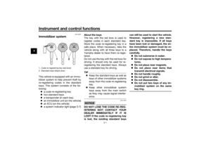 16
16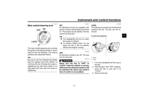 17
17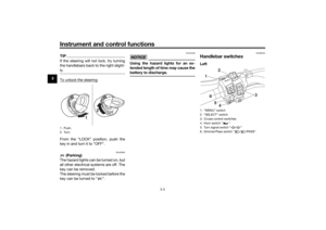 18
18 19
19 20
20 21
21 22
22 23
23 24
24 25
25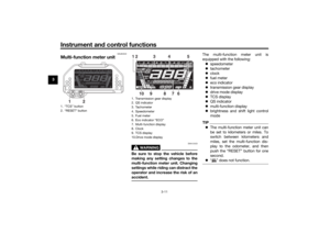 26
26 27
27 28
28 29
29 30
30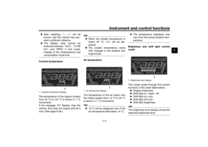 31
31 32
32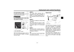 33
33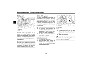 34
34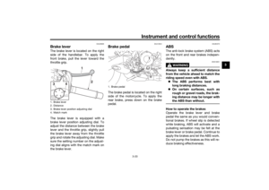 35
35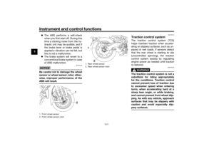 36
36 37
37 38
38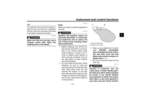 39
39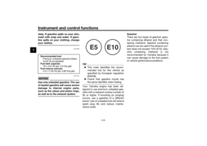 40
40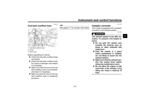 41
41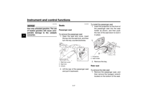 42
42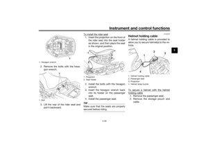 43
43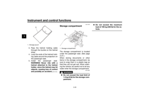 44
44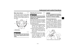 45
45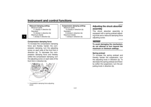 46
46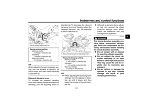 47
47 48
48 49
49 50
50 51
51 52
52 53
53 54
54 55
55 56
56 57
57 58
58 59
59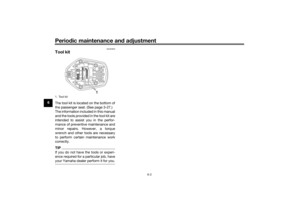 60
60 61
61 62
62 63
63 64
64 65
65 66
66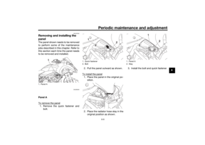 67
67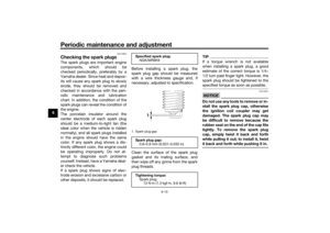 68
68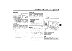 69
69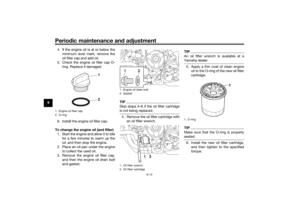 70
70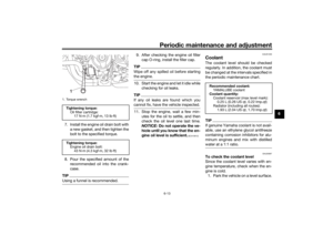 71
71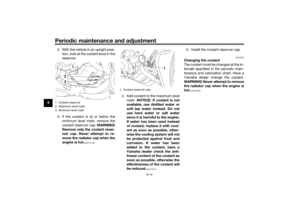 72
72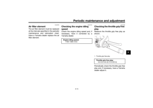 73
73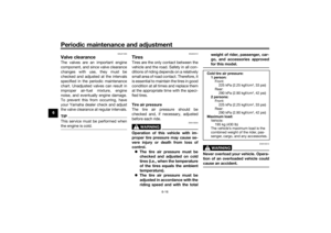 74
74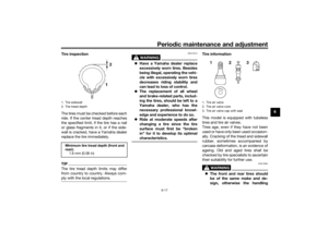 75
75 76
76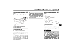 77
77 78
78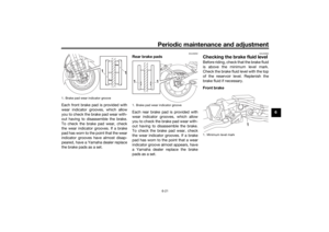 79
79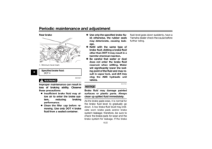 80
80 81
81 82
82 83
83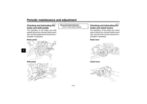 84
84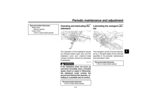 85
85 86
86 87
87 88
88 89
89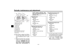 90
90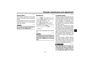 91
91 92
92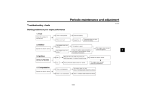 93
93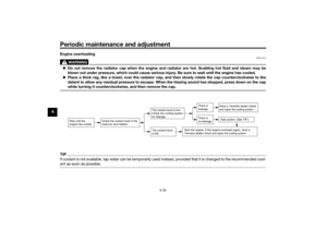 94
94 95
95 96
96 97
97 98
98 99
99 100
100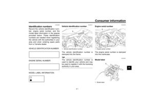 101
101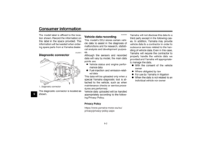 102
102 103
103 104
104 105
105
Front brake:Type:
Hydraulic disc brakeRear brake:Type:
Hydraulic single disc brakeFront suspension:Type:Telescopic fork")
