Page 65 of 102

Periodic maintenance and adjustment
6-17
6
WARNING
EWA10512
Never overload your vehicle. Opera-
tion of an overloaded vehicle could
cause an accident.
Tire inspection
The tires must be checked before each
ride. If the center tread depth reaches
the specified limit, if the tire has a nail
or glass fragments in it, or if the side-
wall is cracked, have a Yamaha dealer
replace the tire immediately.
TIP
The tire tread depth limits may differ
from country to country. Always com-
ply with the local regulations.
WARNING
EWA10472
Have a Yamaha dealer replace
excessively worn tires. Besides
being illegal, operating the vehi-
cle with excessively worn tires
decreases riding stability and
can lead to loss of control.
The replacement of all wheel
and brake-related parts, includ-
ing the tires, should be left to a
Yamaha dealer, who has the
necessary professional knowl-
edge and experience to do so.
Ride at moderate speeds after
changing a tire since the tire
surface must first be “broken
in” for it to develop its optimal
characteristics.
Tire information
This model is equipped with tubeless
tires and rubber tire air valves.
Tire air pressure (measured on cold
tires):
Front:
225 kPa (2.25 kgf/cm², 33 psi)
Rear:
250 kPa (2.50 kgf/cm², 36 psi)
High-speed riding:
Front:
225 kPa (2.25 kgf/cm², 33 psi)
Rear:
250 kPa (2.50 kgf/cm², 36 psi)
Maximum load*:
180 kg (397 lb)
* Total weight of rider, passenger, car-
go and accessories
1. Tire sidewall
2. Tire tread depth
Minimum tire tread depth (front and
rear):
1.6 mm (0.06 in)
1. Tire air valve
2. Tire air valve core
3. Tire air valve cap with seal
UBC6E2E0.book Page 17 Tuesday, July 10, 2018 6:26 PM
Page 66 of 102

Periodic maintenance and adjustment
6-18
6Tires age, even if they have not been
used or have only been used occasion-
ally. Cracking of the tread and sidewall
rubber, sometimes accompanied by
carcass deformation, is an evidence of
ageing. Old and aged tires shall be
checked by tire specialists to ascertain
their suitability for further use.
WARNING
EWA10482
The front and rear tires should
be of the same make and de-
sign, otherwise the handling
characteristics of the motorcy-
cle may be different, which
could lead to an accident.
Always make sure that the valve
caps are securely installed to
prevent air pressure leakage.
Use only the tire valves and
valve cores listed below to
avoid tire deflation during a
high-speed ride.
After extensive tests, only the tires list-
ed below have been approved for this
model by Yamaha.
WARNING
EWA10601
This motorcycle is fitted with super-
high-speed tires. Note the following
points in order to make the most ef-
ficient use of these tires.
Use only the specified replace-
ment tires. Other tires may run
the danger of bursting at super
high speeds.
Brand-new tires can have a rel-
atively poor grip on certain road
surfaces until they have been
“broken in”. Therefore, it is ad-
visable before doing any high-
speed riding to ride conserva-
tively for approximately 100 km
(60 mi) after installing a new tire.
The tires must be warmed up
before a high-speed run.
Always adjust the tire air pres-
sure according to the operating
conditions.
Front tire:
Size:
120/70 ZR 17 M/C (58W)
Manufacturer/model:
MICHELIN/PILOT ROAD 4
Rear tire:
Size:
180/55 ZR 17 M/C (73W)
Manufacturer/model:
MICHELIN/PILOT ROAD 4 R TL
FRONT and REAR:
Tire air valve:
TR412
Valve core:
#9100 (original)
UBC6E2E0.book Page 18 Tuesday, July 10, 2018 6:26 PM
Page 67 of 102

Periodic maintenance and adjustment
6-19
6
EAU21963
Cast wheels
To maximize the performance, durabil-
ity, and safe operation of your vehicle,
note the following points regarding the
specified wheels.
The wheel rims should be
checked for cracks, bends, warp-
age or other damage before each
ride. If any damage is found, have
a Yamaha dealer replace the
wheel. Do not attempt even the
smallest repair to the wheel. A de-
formed or cracked wheel must be
replaced.
The wheel should be balanced
whenever either the tire or wheel
has been changed or replaced. An
unbalanced wheel can result in
poor performance, adverse han-
dling characteristics, and a short-
ened tire life.
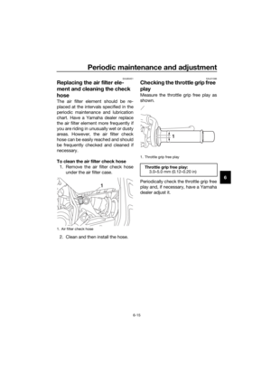
EAU33892
Adjusting the clutch lever free
play
The clutch lever free play should mea-
sure 5.0–10.0 mm (0.20–0.39 in) as
shown. Periodically check the clutch
lever free play and, if necessary, adjust
it as follows.
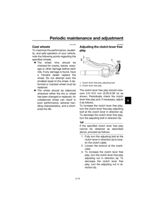
To increase the clutch lever free play,
turn the clutch lever free play adjusting
bolt at the clutch lever in direction (a).
To decrease the clutch lever free play,
turn the adjusting bolt in direction (b).
TIP
If the specified clutch lever free play
cannot be obtained as described
above, proceed as follows.
1. Fully turn the adjusting bolt at the
clutch lever in direction (a) to loos-
en the clutch cable.
2. Loosen the locknut at the crank-
case.
3. To increase the clutch lever free
play, turn the clutch lever free play
adjusting nut in direction (a). To
decrease the clutch lever free
play, turn the adjusting nut in di-
rection (b).
1. Clutch lever free play adjusting bolt
2. Clutch lever free play
21
(b)(a)
UBC6E2E0.book Page 19 Tuesday, July 10, 2018 6:26 PM
Page 68 of 102
Periodic maintenance and adjustment
6-20
64. Tighten the locknut.
EAU37914
Checking the brake lever free
play
There should be no free play at the
brake lever end. If there is free play,
have a Yamaha dealer inspect the
brake system.
WARNING
EWA14212
A soft or spongy feeling in the brake
lever can indicate the presence of
air in the hydraulic system. If there is
air in the hydraulic system, have a
Yamaha dealer bleed the system be-
fore operating the vehicle. Air in the
hydraulic system will diminish the
braking performance, which may re-
sult in loss of control and an acci-
dent.
1. Locknut
2. Clutch lever free play adjusting nut
12
(a)
(b)
1. No brake lever free play
1
UBC6E2E0.book Page 20 Tuesday, July 10, 2018 6:26 PM
Page 69 of 102
Periodic maintenance and adjustment
6-21
6
EAU36504
Brake light switches
The brake light, which is activated by
the brake pedal and brake lever,
should come on just before braking
takes effect. If necessary, have a
Yamaha dealer adjust the brake light
switches.
EAU22393
Checking the front and rear
brake pads
The front and rear brake pads must be
checked for wear at the intervals spec-
ified in the periodic maintenance and
lubrication chart.
EAU36891Front brake pads
Each front brake pad is provided with
wear indicators, which allows you to
check the brake pad wear without hav-
ing to disassemble the brake. To check
the brake pad wear, check the position
of the wear indicators while applying
the brake. If a brake pad has worn to
the point that a wear indicator almost
touches the brake disc, have a
Yamaha dealer replace the brake pads
as a set.
1. Brake pad wear indicator
ZAUM1416
11
UBC6E2E0.book Page 21 Tuesday, July 10, 2018 6:26 PM
Page 70 of 102

Periodic maintenance and adjustment
6-22
6
EAU46292Rear brake pads
Each rear brake pad is provided with
wear indicator grooves, which allow
you to check the brake pad wear with-
out having to disassemble the brake.
To check the brake pad wear, check
the wear indicator grooves. If a brake
pad has worn to the point that a wear
indicator groove almost appears, have
a Yamaha dealer replace the brake
pads as a set.EAU40262
Checking the brake fluid level
Before riding, check that the brake fluid
is above the minimum level mark.
Check the brake fluid level with the top
of the reservoir level. Replenish the
brake fluid if necessary.
Front brake
Rear brake
WARNING
EWA16011
Improper maintenance can result in
loss of braking ability. Observe
these precautions:
Insufficient brake fluid may al-
low air to enter the brake sys-
tem, reducing braking
performance.
1. Brake pad wear indicator groove
ZAUM1417
11
1. Minimum level mark
1. Minimum level mark
Specified brake fluid:
DOT 4
1
1
UBC6E2E0.book Page 22 Tuesday, July 10, 2018 6:26 PM
Page 71 of 102

Periodic maintenance and adjustment
6-23
6 Clean the filler cap before re-
moving. Use only DOT 4 brake
fluid from a sealed container.
Use only the specified brake flu-
id; otherwise, the rubber seals
may deteriorate, causing leak-
age.
Refill with the same type of
brake fluid. Adding a brake fluid
other than DOT 4 may result in a
harmful chemical reaction.
Be careful that water or dust
does not enter the brake fluid
reservoir when refilling. Water
will significantly lower the boil-
ing point of the fluid and may re-
sult in vapor lock, and dirt may
clog the ABS hydraulic unit
valves.
NOTICE
ECA17641
Brake fluid may damage painted
surfaces or plastic parts. Always
clean up spilled fluid immediately.
As the brake pads wear, it is normal for
the brake fluid level to gradually go
down. A low brake fluid level may indi-
cate worn brake pads and/or brake
system leakage; therefore, be sure to
check the brake pads for wear and the
brake system for leakage. If the brake
fluid level goes down suddenly, have a
Yamaha dealer check the cause before
further riding.
EAU22733
Changing the brake fluid
Have a Yamaha dealer change the
brake fluid at the intervals specified in
the periodic maintenance and lubrica-
tion chart. In addition, have the oil seals
of the master cylinders and calipers as
well as the brake hoses replaced at the
intervals listed below or whenever they
are damaged or leaking.
Oil seals: Replace every two
years.
Brake hoses: Replace every four
years.
UBC6E2E0.book Page 23 Tuesday, July 10, 2018 6:26 PM
Page 72 of 102

Periodic maintenance and adjustment
6-24
6
EAU22762
Drive chain slack
The drive chain slack should be
checked before each ride and adjusted
if necessary.
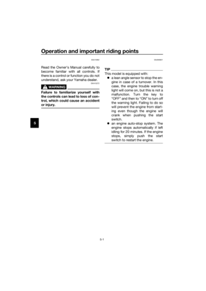
EAU60046To check the drive chain slack
1. Place the motorcycle on the side-
stand.
TIP
When checking and adjusting the drive
chain slack, there should be no weight
on the motorcycle.
2. Shift the transmission into the
neutral position.
3. Push down on the drive chain un-
der the end of the drive chain
guard.
4. Measure distance A between the
drive chain guard and the center
of the chain as shown.
5. If distance A is incorrect, adjust it
as follows. NOTICE: Improper
drive chain slack will overload
the engine as well as other vital
parts of the motorcycle and canlead to chain slippage or break-
age. If distance A is more than
58.0 mm (2.28 in), the chain can
damage the frame, swingarm,
and other parts. To prevent this
from occurring, keep the drive
chain slack within the specified
limits.
[ECA23070]
EAU74260
To adjust the drive chain slack
Consult a Yamaha dealer before ad-
justing the drive chain slack.
1. Loosen the axle nut and the lock-
nut on each side of the swingarm.
2. To tighten the drive chain, turn the
drive chain slack adjusting bolt on
each side of the swingarm in di-
rection (a). To loosen the drive
chain, turn the adjusting bolt on
each side of the swingarm in di-
rection (b), and then push the rear
wheel forward.
1. Drive chain guide
2. Distance A
Distance A:
30.0–35.0 mm (1.18–1.38 in)
2
11. Locknut
2. Axle nut
ZAUM1426
12
UBC6E2E0.book Page 24 Tuesday, July 10, 2018 6:26 PM