Page 33 of 102

Instrument and control functions
3-19
3
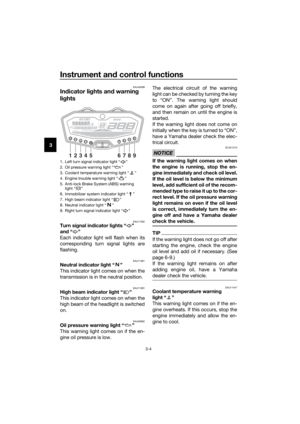
EAU55512
Fuel tank breather hose and
overflow hose
Before operating the motorcycle:
Check each hose connection.
Check each hose for cracks or
damage, and replace if necessary.
Make sure that the end of each
hose is not blocked, and clean if
necessary.
Make sure that each hose is rout-
ed through the clamp.
Make sure that the paint mark on
each hose is below the clamp.
EAU13434
Catalytic converter
This model is equipped with a catalytic
converter in the exhaust system.
WARNING
EWA10863
The exhaust system is hot after op-
eration. To prevent a fire hazard or
burns:
Do not park the vehicle near
possible fire hazards such as
grass or other materials that
easily burn.
Park the vehicle in a place
where pedestrians or children
are not likely to touch the hot
exhaust system.
Make sure that the exhaust sys-
tem has cooled down before
doing any maintenance work.
Do not allow the engine to idle
more than a few minutes. Long
idling can cause a build-up of
heat.
NOTICE
ECA10702
Use only unleaded gasoline. The use
of leaded gasoline will cause unre-
pairable damage to the catalytic
converter.
1. Fuel tank overflow hose
2. Fuel tank breather hose
3. Clamp
4. Original position (paint mark)
ZAUM1343
12
34
UBC6E2E0.book Page 19 Tuesday, July 10, 2018 6:26 PM
Page 34 of 102
Instrument and control functions
3-20
3
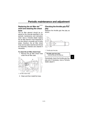
EAUM3740
Seat
To remove the seat
Insert the key into the seat lock, turn it
counterclockwise, and then pull the
seat off.
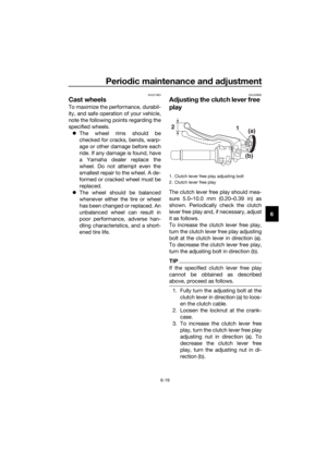
To install the seat
Insert the projection on the front of the
seat into the seat holder, orient the
seat in order to insert the seat bracket
into the seat lock, push the rear of the
seat down to lock it in place, and then
remove the key.
TIP
Make sure that the seat is properly se-
cured before riding.
1. Seat lock
2. Unlock.
1. Projection
2. Seat holder
3. Seat bracket
4. Seat lock
1
2
ZAUM1406
ZAUM1407
1
1
2
4
3
UBC6E2E0.book Page 20 Tuesday, July 10, 2018 6:26 PM
Page 35 of 102

Instrument and control functions
3-21
3
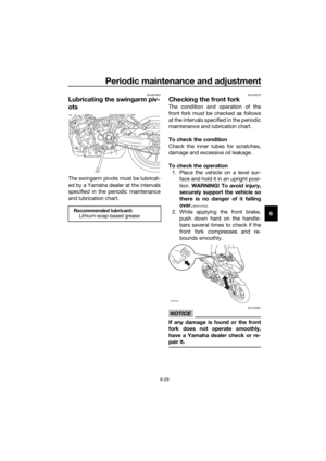
EAUM3800
Helmet holding cable
The helmet holder is located under the
seat. A helmet holding cable is provid-
ed in the owner’s tool kit to secure a
helmet to the helmet holder.
To secure a helmet with the helmet
holding cable
1. Remove the seat. (See page 3-20.)
2. Pass the helmet holding cable
through the buckle on the helmet
strap buckle as shown, and then
hook the cable loops over the hel-
met holder.
3. Place the helmet on the left or the
right side of the vehicle or on the
top of the fuel tank, and then in-
stall the seat. WARNING! Never
ride with a helmet attached to
the helmet holder, since the hel-
met may hit objects, causing
loss of control and possibly an
accident.
[EWA10162]
To release the helmet from the hel-
met holding cable
Remove the seat, remove the helmet
holding cable from the helmet holder
and the helmet, and then install the
seat.
1. Helmet strap buckle
2. Helmet holding cable
3. Helmet holder
2
1
3
ZAUM1408
UBC6E2E0.book Page 21 Tuesday, July 10, 2018 6:26 PM
Page 36 of 102

Instrument and control functions
3-22
3
EAU14465
Storage compartment
The storage compartment is located
under the passenger seat.
When storing documents or other
items in the storage compartment, be
sure to wrap them in a plastic bag so
that they will not get wet. When wash-
ing the vehicle, be careful not to let any
water enter the storage compartment.
WARNING
EWA10962
Do not exceed the load limit of
1.5 kg for the storage compart-
ment.
Do not exceed the maximum
load of 180 kg (397 lb) for the ve-
hicle.
EAUM3811
Windshield
To suit the rider’s preference, the wind-
shield can be changed to different po-
sitions.
To adjust the windshield height
1. Loosen the windshield height po-
sition adjusting knob on each side
of the windshield until resistance
is felt. NOTICE: Do not continue
turning the knob after resis-
tance is felt. Otherwise, the
knob could be damaged.
[ECA20211]
2. Adjust the windshield at the de-
sired height.
3. Tighten the adjusting knobs.
1. Storage compartment
ZAUM1425
1
1. Windshield height position adjusting knob
1
ZAUM1409
UBC6E2E0.book Page 22 Tuesday, July 10, 2018 6:26 PM
Page 37 of 102

Instrument and control functions
3-23
3
EAU47001
Adjusting the shock absorber
assembly
This shock absorber assembly is
equipped with a spring preload adjust-
ing ring.
NOTICE
ECA10102
To avoid damaging the mechanism,
do not attempt to turn beyond the
maximum or minimum settings.
Adjust the spring preload as follows.
To increase the spring preload and
thereby harden the suspension, turn
the adjusting ring in direction (a). To
decrease the spring preload and there-
by soften the suspension, turn the ad-
justing ring in direction (b).
Align the appropriate notch in the
adjusting ring with the position in-
dicator on the shock absorber.
Use the special wrench and ex-
tension bar included in the own-
er’s tool kit to make the
adjustment.
WARNING
EWA10222
This shock absorber assembly con-
tains highly pressurized nitrogen
gas. Read and understand the fol-
lowing information before handling
the shock absorber assembly.
Do not tamper with or attempt
to open the cylinder assembly.
Do not subject the shock ab-
sorber assembly to an open
flame or other high heat source.
This may cause the unit to ex-
plode due to excessive gas
pressure.
Do not deform or damage the
cylinder in any way. Cylinder
damage will result in poor
damping performance.
Do not dispose of a damaged or
worn-out shock ab
sorber as-
sembly yourself. Take the shock
absorber assembly to a Yamaha
dealer for any service.
1. Extension bar
2. Special wrench
3. Spring preload adjusting ring
4. Position indicator
7 69 8 5 4 3 2 1
3(a)(b)
2
1
4
Spring preload setting:
Minimum (soft):
1
Standard:
3
Maximum (hard):
9
UBC6E2E0.book Page 23 Tuesday, July 10, 2018 6:26 PM
Page 38 of 102

Instrument and control functions
3-24
3
EAUM3770
Luggage strap holders
There are two luggage strap holders on
the rear of the machine.
EAU15306
Sidestand
The sidestand is located on the left
side of the frame. Raise the sidestand
or lower it with your foot while holding
the vehicle upright.
TIP
The built-in sidestand switch is part of
the ignition circuit cut-off system,
which cuts the ignition in certain situa-
tions. (See the following section for an
explanation of the ignition circuit cut-
off system.)
WARNING
EWA10242
The vehicle must not be ridden with
the sidestand down, or if the side-
stand cannot be properly moved up
(or does not stay up), otherwise the
sidestand could contact the ground
and distract the operator, resulting
in a possible loss of control.
Yamaha’s ignition circuit cut-off
system has been designed to assist
the operator in fulfilling the respon-
sibility of raising the sidestand be-
fore starting off. Therefore, check
this system regularly and have a
Yamaha dealer repair it if it does not
function properly.
1. Luggage strap holder
1
ZAUM1410
UBC6E2E0.book Page 24 Tuesday, July 10, 2018 6:26 PM
Page 39 of 102
Instrument and control functions
3-25
3
EAU68740
Ignition circuit cut-off system
The ignition circuit cut-off system
(comprising the sidestand switch,
clutch switch and neutral switch) has
the following functions.
It prevents starting when the
transmission is in gear and the
sidestand is up, but the clutch le-
ver is not pulled.
It prevents starting when the
transmission is in gear and the
clutch lever is pulled, but the side-
stand is still down.
It cuts the running engine when
the transmission is in gear and the
sidestand is moved down.
Periodically check the operation of the
ignition circuit cut-off system accord-
ing to the following procedure.
UBC6E2E0.book Page 25 Tuesday, July 10, 2018 6:26 PM
Page 40 of 102

Instrument and control functions
3-26
3
With the engine turned off:
1. Move the sidestand down.
2.
Make sure that the start/engine stop
switch is set to “ ”.
3. Turn the key on.
4. Shift the transmission into the neutral
position.
5.
Slide the switch toward “ ”.
Does the engine start?
With the engine still running:
6. Move the sidestand up.
7. Keep the clutch lever pulled.
8. Shift the transmission into gear.
9. Move the sidestand down.
Does the engine stall?
After the engine has stalled:
10. Move the sidestand up.
11. Keep the clutch lever pulled.
12.
Slide the switch toward “ ”.
Does the engine start?
The system is OK. The motorcycle can
be ridden.
The neutral switch may not be working
correctly.
The motorcycle should not be ridden
until checked by a Yamaha dealer.
The sidestand switch may not be
working correctly.
The motorcycle should not be ridden
until checked by a Yamaha dealer.
The clutch switch may not be working
correctly.
The motorcycle should not be ridden
until checked by a Yamaha dealer.
WARNING
If a malfunction is noted, have a
Yamaha dealer check the system
before riding.
YES NO
YES NO
YES NO
UBC6E2E0.book Page 26 Tuesday, July 10, 2018 6:26 PM


 has
the followi")