Page 41 of 104

Instrument and control functions
4-23
1
2
345
6
7
8
9
10
11
12
of a damping force adjusting
mechanism may not exactly match
the above specifications due to
small differences in production, the
actual number of clicks always
represents the entire adjusting
range. To obtain a precise adjust-
ment, check the number of clicks
of each damping force adjusting
mechanism and modify the specifi-
cations as necessary.
When turning a damping force ad-
juster in direction (a), the 0 click
position and the 1 click positionmay be the same.
EAU57941
Adjusting the shock absorber
assemblyThis shock absorber assembly is
equipped with a spring preload adjust-
ing ring and a rebound damping force
adjusting screw.NOTICE
ECA10102
To avoid damaging the mechanism,
do not attempt to turn beyond themaximum or minimum settings.
Spring preload
To increase the spring preload and
thereby harden the suspension, turn
the adjusting ring in direction (a). To de-
crease the spring preload and thereby
soften the suspension, turn the adjust-
ing ring in direction (b).
Align the appropriate notch in the
adjusting ring with the position in-
dicator on the shock absorber.
Use the special wrench and the
extension bar included in the own-
er’s tool kit to make the adjust-
ment.
1. Spring preload adjusting ring
2. Special wrench
3. Extension bar
4. Position indicatorSpring preload setting:
Minimum (soft):1
Standard:
4
Maximum (hard): 7
7654321
1(b) (a)
4
2
3
BS2-9-E1E0_1.book 23 ページ 2018年4月27日 金曜日 午後4時50分
Page 42 of 104

Instrument and control functions
4-24
1
2
34
5
6
7
8
9
10
11
12 Rebound damping force
To increase the rebound damping force
and thereby harden the rebound damp-
ing, turn the adjusting screw in direction
(a). To decrease the rebound damping
force and thereby soften the rebound
damping, turn the adjusting screw in di-
rection (b).
TIPTo obtain a precise adjustment, it is ad-
visable to check the actual total number
of turns of the damping force adjusting
mechanism. This adjustment range
may not exactly match the specifica-
tions listed due to small differences inproduction.
WARNING
EWA10222
This shock absorber assembly con-
tains highly pressurized nitrogen
gas. Read and understand the fol-
lowing information before handling
the shock absorber assembly.
Do not tamper with or attempt to
open the cylinder assembly.
Do not subject the shock ab-
sorber assembly to an open
flame or other high heat source.
This may cause the unit to ex-
plode due to excessive gas
pressure.
Do not deform or damage the
cylinder in any way. Cylinder
damage will result in poor
damping performance.
Do not dispose of a damaged or worn-out shock absorber as-
sembly yourself. Take the shock
absorber assembly to a Yamaha
dealer for any service.
1. Rebound damping force adjusting screwRebound damping setting:
Minimum (soft):
3 turn(s) in direction (b)*
Standard: 1.5 turn(s) in direction (b)*
Maximum (hard): 0 turn(s) in direction (b)*
* With the adjusting screw fully turned
in direction (a)
1 (a)(b)
BS2-9-E1E0_1.book 24 ページ 2018年4月27日 金曜日 午後4時50分
Page 43 of 104

Instrument and control functions
4-25
1
2
345
6
7
8
9
10
11
12
EAU15152
Luggage strap holdersThere is a luggage strap holder on each
passenger footrest.
EAU77390
Auxiliary DC connectorsThis vehicle is equipped with an auxilia-
ry DC connector and a grip warmer DC
connector. Consult your Yamaha deal-
er before installing any accessories.
EAU15306
SidestandThe sidestand is located on the left side
of the frame. Raise the sidestand or
lower it with your foot while holding the
vehicle upright.TIPThe built-in sidestand switch is part of
the ignition circuit cut-off system, which
cuts the ignition in certain situations.
(See the following section for an expla-
nation of the ignition circuit cut-off sys-tem.)
WARNING
EWA10242
The vehicle must not be ridden with
the sidestand down, or if the sides-
tand cannot be properly moved up
(or does not stay up), otherwise the
sidestand could contact the ground
and distract the operator, resulting
in a possible loss of control.
Yamaha’s ignition circuit cut-off
system has been designed to assist
the operator in fulfilling the respon-
sibility of raising the sidestand be-
fore starting off. Therefore, check
this system regularly and have a
1. Luggage strap holder
1
BS2-9-E1E0_1.book 25 ページ 2018年4月27日 金曜日 午後4時50分
Page 44 of 104
Instrument and control functions
4-26
1
2
34
5
6
7
8
9
10
11
12 Yamaha dealer repair it if it does not
function properly.
EAU57951
Ignition circuit cut-off systemThis system prevents in-gear engine
starts unless the clutch lever is pulled
and the sidestand is up. Also, it will stop
the running engine should the sides-
tand be lowered while the transmission
is in gear.
Periodically check the system via the
following procedure.TIP
This check is most reliable if per-
formed with a warmed-up engine.
See pages 4-2 and 4-4 for switchoperation information.
BS2-9-E1E0_1.book 26 ページ 2018年4月27日 金曜日 午後4時50分
Page 45 of 104

Instrument and control functions
4-27
1
2
345
6
7
8
9
10
11
12
With the engine turned off:
1. Move the sidestand down.
2. Set engine stop s witch to run position.
3. T urn m ain switch to on position.
4. Shift tr ansmission into neutr al.
5. Push the start switch.
Does the engine start?
With the engine still r unning:
6. Move the sidestand up.
7. Pull the clutch lever.
8. Shift tr ansmission into gear.
9. Move the sidestand down.
Does the en gine stall?
After the engine has stalled:
10.
Move the sidestand up.
11. Pull the clutch lever.
12. Push the start switch.
Does the engine start?
The system is OK. The motorcycle can be ridden.
YES NO
YES
NO
YES
NO
The neutral switch ma y not be working.
The motorcycle should not be ridden until
checked b y a Yamaha dealer.
The clutch s witch may not be working.
The motorcycle should not be ridden until
checked b y a Yamaha dealer.The sidestand s witch may not be working.
The motorcycle should not be ridden until
checked b y a Yamaha dealer.If a malfunction is found, have the vehicle
inspected before riding.
WARNING
BS2-9-E1E0_1.book 27 ページ 2018年4月27日 金曜日 午後4時50分
Page 46 of 104

5-1
1
2
3
45
6
7
8
9
10
11
12
For your safety – pre-operation checks
EAU15599
Inspect your vehicle each time you use it to make sure the vehi cle is in safe operating condition. Always follow the inspection
and maintenance procedures and schedules described in the Owner’s Manual.
WARNING
EWA11152
Failure to inspect or maintain the vehicle properly increases the possibility of an accident or equipment damage.
Do not operate the vehicle if you find any problem. If a problem cannot be corrected by the procedures provided inthis manual, have the vehicle inspected by a Yamaha dealer.
Before using this vehicle, check the following points:
ITEM CHECKS PAGE
Fuel Check fuel level in fuel tank.
Refuel if necessary.
Check fuel line for leakage.
Check fuel tank breather hose and overflow hose for obstructions, cracks or
damage, and check hose connections. 4-17, 4-19
Engine oil Check oil level in engine.
If necessary, add recommended oil to specified level.
Check vehicle for oil leakage. 7-12
Coolant Check coolant level in reservoir.
If necessary, add recommended coolant to specified level.
Check cooling system for leakage. 7-14
Front brake Check operation.
If soft or spongy, have Yamaha dealer bleed hydraulic system.
Check brake pads for wear.
Replace if necessary.
Check fluid level in reservoir.
If necessary, add specified brake fluid to specified level.
Check hydraulic system for leakage. 7-21, 7-22
BS2-9-E1E0_1.book 1 ページ 2018年4月27日 金曜日 午後4時50分
Page 47 of 104

For your safety – pre-operation checks
5-2
1
2
3
456
7
8
9
10
11
12
Rear brake Check operation.
If soft or spongy, have Yamaha dealer bleed hydraulic system.
Check brake pads for wear.
Replace if necessary.
Check fluid level in reservoir.
If necessary, add specified brake fluid to specified level.
Check hydraulic system for leakage. 7-21, 7-22
Clutch Check operation.
Lubricate cable if necessary.
Check lever free play.
Adjust if necessary. 7-20
Throttle grip Make sure that operation is smooth.
Check throttle grip free play.
If necessary, have Yamaha dealer adjust th
rottle grip free play and lubricate cable
and grip housing. 7-16, 7-26
Control cables Make sure that operation is smooth.
Lubricate if necessary. 7-26
Drive chain Check chain slack.
Adjust if necessary.
Check chain condition.
Lubricate if necessary. 7-24, 7-25
Wheels and tires Check for damage.
Check tire condition and tread depth.
Check air pressure.
Correct if necessary. 7-17, 7-19
Brake and shift pedals Make sure that operation is smooth.
Lubricate pedal pivoting points if necessary. 7-27
Brake and clutch levers Make sure that operation is smooth.
Lubricate lever pivoting points if necessary. 7-27
Sidestand Make sure that operation is smooth.
Lubricate pivot if necessary. 7-28
Chassis fasteners Make sure that all nuts, bolts and screws are properly tightened.
Tighten if necessary. —
ITEM CHECKS PAGE
BS2-9-E1E0_1.book 2 ページ 2018年4月27日 金曜日 午後4時50分
Page 48 of 104
For your safety – pre-operation checks
5-3
1
2
3
45
6
7
8
9
10
11
12
Instruments, lights, signals
and switches Check operation.
Correct if necessary.
—
Sidestand switch Check operation of ignition circuit cut-off system.
If system is not working correctly, have Yamaha dealer check vehicle. 4-25
ITEM CHECKS PAGE
BS2-9-E1E0_1.book 3 ページ 2018年4月27日 金曜日 午後4時50分
 1
1 2
2 3
3 4
4 5
5 6
6 7
7 8
8 9
9 10
10 11
11 12
12 13
13 14
14 15
15 16
16 17
17 18
18 19
19 20
20 21
21 22
22 23
23 24
24 25
25 26
26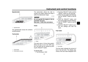 27
27 28
28 29
29 30
30 31
31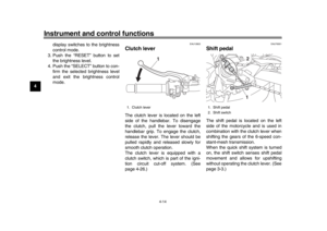 32
32 33
33 34
34 35
35 36
36 37
37 38
38 39
39 40
40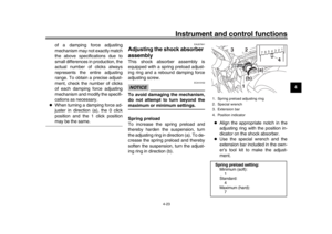 41
41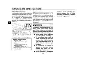 42
42 43
43 44
44 45
45 46
46 47
47 48
48 49
49 50
50 51
51 52
52 53
53 54
54 55
55 56
56 57
57 58
58 59
59 60
60 61
61 62
62 63
63 64
64 65
65 66
66 67
67 68
68 69
69 70
70 71
71 72
72 73
73 74
74 75
75 76
76 77
77 78
78 79
79 80
80 81
81 82
82 83
83 84
84 85
85 86
86 87
87 88
88 89
89 90
90 91
91 92
92 93
93 94
94 95
95 96
96 97
97 98
98 99
99 100
100 101
101 102
102 103
103
