Page 33 of 104
Instrument and control functions
4-15
1
2
345
6
7
8
9
10
11
12
EAU26825
Brake leverThe brake lever is located on the right
side of the handlebar. To apply the front
brake, pull the lever toward the throttle
grip.
The brake lever is equipped with a
brake lever position adjusting dial. To
adjust the distance between the brake
lever and the throttle grip, turn the ad-
justing dial while holding the lever
pushed away from the throttle grip.
Make sure that the appropriate setting
on the adjusting dial is aligned with the “ ” mark on the brake lever.
EAU12944
Brake pedalThe brake pedal is located on the right
side of the motorcycle. To apply the
rear brake, press down on the brake
pedal.
1. Brake lever
2. Distance between brake lever and throttle
grip
3. Brake lever position adjusting dial
4. “ ” mark
5 4 3 2 1
1
2
43
1. Brake pedal
1
BS2-9-E1E0_1.book 15 ページ 2018年4月27日 金曜日 午後4時50分
Page 34 of 104
 features a dual electronic con-
trol system, which acts on the front and
rear brakes")
Instrument and control functions
4-16
1
2
34
5
6
7
8
9
10
11
12
EAU63040
ABSThe Yamaha ABS (Anti-lock Brake
System) features a dual electronic con-
trol system, which acts on the front and
rear brakes independently.
Operate the brakes with ABS as you
would conventional brakes. If the ABS
is activated, a pulsating sensation may
be felt at the brake lever or brake pedal.
In this situation, continue to apply the
brakes and let the ABS work; do not
“pump” the brakes as this will reduce
braking effectiveness.
WARNING
EWA16051
Always keep a sufficient distance
from the vehicle ahead to match the
riding speed even with ABS.
The ABS performs best with
long braking distances.
On certain surfaces, such as
rough or gravel roads, the brak-
ing distance may be longer withthe ABS than without.
The ABS is monitored by an ECU,
which will revert the system to conven-
tional braking if a malfunction occurs.
TIP
The ABS performs a self-diagno-
sis test each time the vehicle first
starts off after the key is turned to
“ON” and the vehicle has traveled
at a speed of 10 km/h (6 mi/h) or
higher. During this test, a “clicking”
noise can be heard from the hy-
draulic control unit, and if the brake
lever or brake pedal is even slight-
ly applied, a vibration can be felt at
the lever and pedal, but these do
not indicate a malfunction.
This ABS has a test mode which
allows the owner to experience the
pulsation at the brake lever or
brake pedal when the ABS is oper-
ating. However, special tools are
required, so please consult yourYamaha dealer.
NOTICE
ECA20100
Be careful not to damage the wheel
sensor or wheel sensor rotor; other-
wise, improper performance of theABS will result.
1. Front wheel sensor
2. Front wheel sensor rotor
1. Rear wheel sensor
2. Rear wheel sensor rotor
1
2
1
2
BS2-9-E1E0_1.book 16 ページ 2018年4月27日 金曜日 午後4時50分
Page 35 of 104

Instrument and control functions
4-17
1
2
345
6
7
8
9
10
11
12
EAU13075
Fuel tank capTo open the fuel tank cap
Open the fuel tank cap lock cover, in-
sert the key into the lock, and then turn
it 1/4 turn clockwise. The lock will be re-
leased and the fuel tank cap can be
opened.
To close the fuel tank cap 1. Push the fuel tank cap into position with the key inserted in the lock.
2. Turn the key counterclockwise to the original position, remove it, and
then close the lock cover.
TIPThe fuel tank cap cannot be closed un-
less the key is in the lock. In addition,
the key cannot be removed if the cap isnot properly closed and locked.
WARNING
EWA11092
Make sure that the fuel tank cap is
properly closed after filling fuel.Leaking fuel is a fire hazard.
EAU13222
FuelMake sure there is sufficient gasoline in
the tank.
WARNING
EWA10882
Gasoline and gasoline vapors are
extremely flammable. To avoid fires
and explosions and to reduce the
risk of injury when refueling, followthese instructions.
1. Before refueling, turn off the en- gine and be sure that no one is sit-
ting on the vehicle. Never refuel
while smoking, or while in the vi-
cinity of sparks, open flames, or
other sources of ignition such as
the pilot lights of water heaters and
clothes dryers.
2. Do not overfill the fuel tank. When refueling, be sure to insert the
pump nozzle into the fuel tank filler
hole. Stop filling when the fuel
reaches the bottom of the filler
tube. Because fuel expands when
it heats up, heat from the engine or
the sun can cause fuel to spill out
of the fuel tank.
1. Unlock.
2. Fuel tank cap lock cover
2
1
BS2-9-E1E0_1.book 17 ページ 2018年4月27日 金曜日 午後4時50分
Page 36 of 104

Instrument and control functions
4-18
1
2
34
5
6
7
8
9
10
11
12 3. Wipe up any spilled fuel immedi-
ately. NOTICE: Immediately wipe
off spilled fuel with a clean, dry,
soft cloth, since fuel may deteri-
orate painted surfaces or plastic
parts.
[ECA10072]
4. Be sure to securely close the fuel tank cap.
WARNING
EWA15152
Gasoline is poisonous and can
cause injury or death. Handle gaso-
line with care. Never siphon gaso-
line by mouth. If you should swallow
some gasoline or inhale a lot of gas-
oline vapor, or get some gasoline in your eyes, see your doctor immedi-
ately. If gasoline spills on your skin,
wash with soap and water. If gaso-
line spills on your clothing, change
your clothes.
EAU75300
NOTICE
ECA11401
Use only unleaded gasoline. The use
of leaded gasoline will cause severe
damage to internal engine parts,
such as the valves and piston rings,as well as to the exhaust system.
TIP
This mark identifies the recom-
mended fuel for this vehicle as
specified by European regulation
(EN228).
Check that gasoline nozzle has thesame identifier when fueling.
Your Yamaha engine has been de-
signed to use premium unleaded gaso-
line with a research octane number of
95 or higher. If knocking (or pinging) oc-
curs, use a gasoline of a different
brand. Use of unleaded fuel will extend
spark plug life and reduce maintenance
costs.
Gasohol
There are two types of gasohol: gaso-
1. Fuel tank filler tube
2. Maximum fuel level
1
2
Recommended fuel: Premium unleaded gasoline (Gaso-
hol [E10] acceptable)
Fuel tank capacity: 14 L (3.7 US gal, 3.1 Imp.gal)
Fuel reserve amount:
2.8 L (0.74 US gal, 0.62 Imp.gal)
E5
E10
BS2-9-E1E0_1.book 18 ページ 2018年4月27日 金曜日 午後4時50分
Page 37 of 104

Instrument and control functions
4-19
1
2
345
6
7
8
9
10
11
12
hol containing ethanol and that contain-
ing methanol. Gasohol containing
ethanol can be used if the ethanol con-
tent does not exceed 10% (E10). Gas-
ohol containing methanol is not
recommended by Yamaha because it
can cause damage to the fuel system
or vehicle performance problems.
EAU72971
Fuel tank overflow hoseBefore operating the vehicle:
check the overflow hose connec-
tion.
check the overflow hose for dam-
age.
confirm the overflow hose is not
blocked.
confirm the overflow hose is routed
through the clamp.
TIPSee page 7-11 for canister information.
EAU13434
Catalytic converterThis model is equipped with a catalytic
converter in the exhaust system.
WARNING
EWA10863
The exhaust system is hot after op-
eration. To prevent a fire hazard or
burns:
Do not park the vehicle near
possible fire hazards such as
grass or other materials that
easily burn.
Park the vehicle in a place
where pedestrians or children
are not likely to touch the hot
exhaust system.
Make sure that the exhaust sys-
tem has cooled down before do-
ing any maintenance work.
Do not allow the engine to idle
more than a few minutes. Long
idling can cause a build-up ofheat.
NOTICE
ECA10702
Use only unleaded gasoline. The use
of leaded gasoline will cause unre-
1. Fuel tank overflow hose
2. Clamp
21
BS2-9-E1E0_1.book 19 ページ 2018年4月27日 金曜日 午後4時50分
Page 38 of 104
Instrument and control functions
4-20
1
2
34
5
6
7
8
9
10
11
12 pairable damage to the catalytic
converter.
EAU57991
SeatTo remove the seat
1. Open the seat lock cover, insert the key into the seat lock, and then
turn the key counterclockwise.
2. While holding the key in that posi- tion, lift the rear of the seat up, and
then pull the seat off.
To install the seat 1. Insert the projections into the seat holders as shown. 2. Push the rear of the seat down to
lock it in place.
3. Remove the key.
TIPMake sure that the seat is properly se-cured before riding.
1. Seat lock
2. Seat lock cover
3. Unlock.1
32
1. Projection
2. Seat holder
1
2
21
BS2-9-E1E0_1.book 20 ページ 2018年4月27日 金曜日 午後4時50分
Page 39 of 104

When storing documents or other items
in")
Instrument and control functions
4-21
1
2
345
6
7
8
9
10
11
12
EAU77030
Storage compartmentThe storage compartment is located
under the seat. (See page 4-20.)
When storing documents or other items
in the storage compartment, be sure to
wrap them in a plastic bag so that they
will not get wet. When washing the ve-
hicle, be careful not to let any water en-
ter the storage compartment.
WARNING
EWA15401
Do not exceed the maximum load of174 kg (384 lb) for the vehicle.
EAU76341
Adjusting the front fork
WARNING
EWA14671
Always adjust the spring preload on
both fork legs equally, otherwise
poor handling and loss of stabilitymay result.
Each front fork leg is equipped with a
spring preload adjusting bolt, the right
front fork leg is equipped with a re-
bound damping force adjusting screw
and the left front fork leg with a com-
pression damping force adjusting
screw.NOTICE
ECA10102
To avoid damaging the mechanism,
do not attempt to turn beyond themaximum or minimum settings.
Spring preload
To increase the spring preload and
thereby harden the suspension, turn
the adjusting bolt on each fork leg in di-
rection (a). To decrease the spring pre-
load and thereby soften the
suspension, turn the adjusting bolt on each fork leg in direction (b).
The spring preload setting is deter-
mined by measuring distance A, shown
in the illustration. The shorter distance
A is, the higher the spring preload; the
longer distance A is, the lower the
spring preload.
1. Storage compartment
1
1. Spring preload adjusting bolt
1. Distance A
1
1
(a)
(b)
(a)
(b)
1
BS2-9-E1E0_1.book 21 ページ 2018年4月27日 金曜日 午後4時50分
Page 40 of 104

Instrument and control functions
4-22
1
2
34
5
6
7
8
9
10
11
12 Rebound damping force
The rebound damping force is adjusted
on the right front fork leg only. To in-
crease the rebound damping force and
thereby harden the rebound damping,
turn the adjusting screw in direction (a).
To decrease the rebound damping
force and thereby soften the rebound
damping, turn the adjusting screw in di-
rection (b).
TIPBe sure to perform this adjustment onthe right front fork leg.
Compression damping force
The compression damping force is ad-
justed on the left front fork leg only. To
increase the compression damping
force and thereby harden the compres-
sion damping, turn the adjusting screw
in direction (a). To decrease the com-
pression damping force and therebysoften the compression damping, turn
the adjusting screw in direction (b).
TIPBe sure to perform this adjustment onthe left front fork leg.TIP
Although the total number of clicks
Spring preload setting:
Minimum (soft):Distance A = 19.0 mm (0.75 in)
Standard:
Distance A = 16.0 mm (0.63 in)
Maximum (hard): Distance A = 4.0 mm (0.16 in)
1. Rebound damping force adjusting screwRebound damping setting: Minimum (soft):
11 click(s) in direction (b)*
Standard: 11 click(s) in direction (b)*
Maximum (hard): 0 click(s) in direction (b)*
* With the adjusting knob fully turned in
direction (a)
1
(a)
(b)
1. Compression damping force adjusting
screwCompression damping setting:Minimum (soft):11 click(s) in direction (b)*
Standard: 11 click(s) in direction (b)*
Maximum (hard):
0 click(s) in direction (b)*
* With the adjusting screw fully turned in direction (a)
1
(a) (b)
BS2-9-E1E0_1.book 22 ページ 2018年4月27日 金曜日 午後4時50分
 1
1 2
2 3
3 4
4 5
5 6
6 7
7 8
8 9
9 10
10 11
11 12
12 13
13 14
14 15
15 16
16 17
17 18
18 19
19 20
20 21
21 22
22 23
23 24
24 25
25 26
26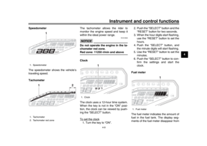 27
27 28
28 29
29 30
30 31
31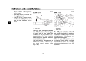 32
32 33
33 34
34 35
35 36
36 37
37 38
38 39
39 40
40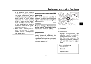 41
41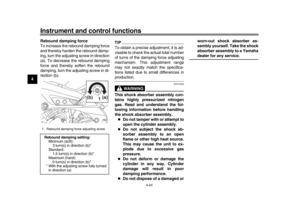 42
42 43
43 44
44 45
45 46
46 47
47 48
48 49
49 50
50 51
51 52
52 53
53 54
54 55
55 56
56 57
57 58
58 59
59 60
60 61
61 62
62 63
63 64
64 65
65 66
66 67
67 68
68 69
69 70
70 71
71 72
72 73
73 74
74 75
75 76
76 77
77 78
78 79
79 80
80 81
81 82
82 83
83 84
84 85
85 86
86 87
87 88
88 89
89 90
90 91
91 92
92 93
93 94
94 95
95 96
96 97
97 98
98 99
99 100
100 101
101 102
102 103
103
