Page 79 of 662
SAFETY
}}
* Option/accessory.77
Folding up the integrated booster
cushion*
When the integrated booster cushion is used, it must be folded up.
Lower position:
Pull the handle forward and upward to release the booster cushion.
Press the booster cushion rearward to lock it into position.
Upper position (from the lower position):
Press the button to release the booster cushion.
Lift the front edge of the booster cushion and press it rearward toward the backrest tolock it into position.
Page 80 of 662

||
SAFETY
* Option/accessory.
78
WARNING
DEATH or SERIOUS INJURY can occur •
Follow all instructions on this child restraint and in the vehicle'sowner's manual.
• Make sure the booster cushion issecurely locked before the childis seated.
• Use this booster cushion only with chil- dren whose height and weight are withinthe permitted limits shown in the table.
• Use only the vehicle's lap and shoulderbelt system when restraining the child inthis booster cushion.
• In the event of a collision while the inte-grated booster cushion was occupied, theentire booster cushion and seat belt mustbe replaced. The booster cushion shouldalso be replaced if it is badly worn ordamaged in any way. This work should beperformed by a trained and qualifiedVolvo service technician only.
NOTE
The integrated booster cushion cannot be moved directly from the upper position to thelower position. From the upper position, thebooster cushion must first be folded downcompletely into the rear seat and then raisedto the lower position.
Related information
•
Integrated booster cushion
* (p. 75)
• Folding down the integrated booster cush- ion
* (p. 78)
Folding down the integrated
booster cushion *
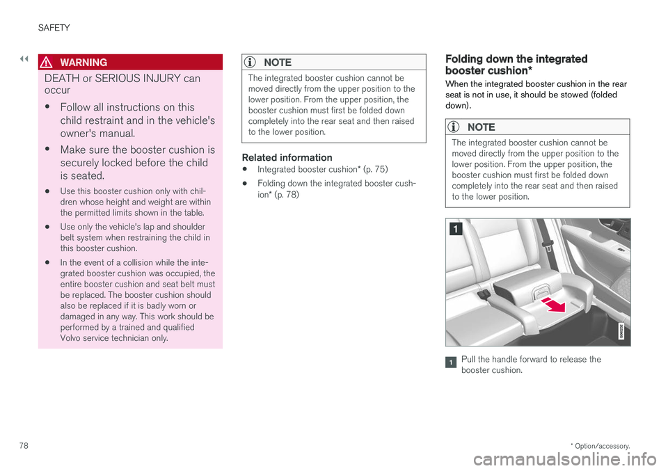
When the integrated booster cushion in the rear seat is not in use, it should be stowed (foldeddown).
NOTE
The integrated booster cushion cannot be moved directly from the upper position to thelower position. From the upper position, thebooster cushion must first be folded downcompletely into the rear seat and then raisedto the lower position.
Pull the handle forward to release the booster cushion.
Page 81 of 662

SAFETY
* Option/accessory.79
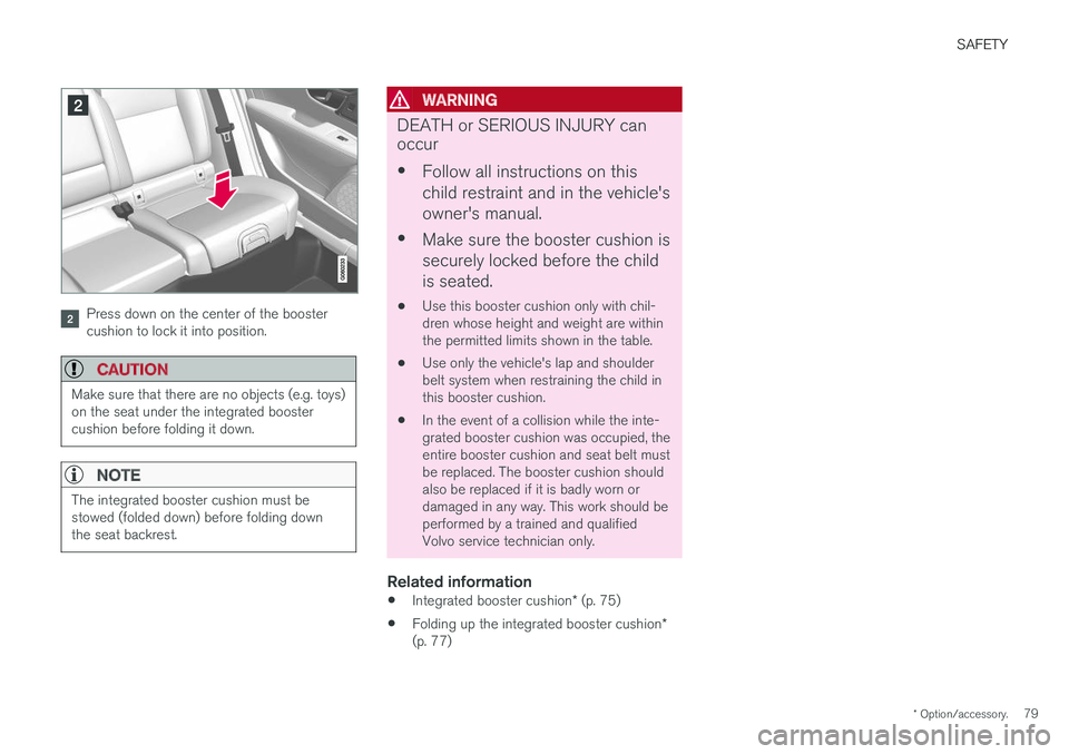
Press down on the center of the booster cushion to lock it into position.
CAUTION
Make sure that there are no objects (e.g. toys) on the seat under the integrated boostercushion before folding it down.
NOTE
The integrated booster cushion must be stowed (folded down) before folding downthe seat backrest.
WARNING
DEATH or SERIOUS INJURY can occur •
Follow all instructions on this child restraint and in the vehicle'sowner's manual.
• Make sure the booster cushion issecurely locked before the childis seated.
• Use this booster cushion only with chil- dren whose height and weight are withinthe permitted limits shown in the table.
• Use only the vehicle's lap and shoulderbelt system when restraining the child inthis booster cushion.
• In the event of a collision while the inte-grated booster cushion was occupied, theentire booster cushion and seat belt mustbe replaced. The booster cushion shouldalso be replaced if it is badly worn ordamaged in any way. This work should beperformed by a trained and qualifiedVolvo service technician only.
Related information
•
Integrated booster cushion
* (p. 75)
• Folding up the integrated booster cushion
*
(p. 77)
Page 84 of 662
DISPLAYS AND VOICE CONTROL
* Option/accessory.
82
Instruments and controls in left-hand drive vehicles
The overviews show the location of the vehicle's
displays and controls.
Steering wheel and dashboard
Parking lights, daytime running lights, low beams, high beams, turn signals, front fog lights/cornering illumination *, rear fog light,
trip computer reset
Steering wheel paddles for manual shifting *
Head-up display*
Instrument panel
Wipers and washers, rain sensor *
Right-side steering wheel keypad
Steering wheel adjustment
Horn
Left-side steering wheel keypad
Hood open
Display lighting, tailgate unlock/open */
close *, halogen headlight height adjustment
Ceiling console
Front reading lights and courtesy lighting
Panoramic roof *
Ceiling console display
HomeLink®
*
Center and tunnel console
Center display
Hazard warning flashers, defrosting, media
Gear selector
Start knob
Drive modes *
Parking brake
Auto-hold brakes
Driver's door
Page 85 of 662
DISPLAYS AND VOICE CONTROL
* Option/accessory.83
Memory for power front seat settings *, door
mirrors and head-up display *
Central locking
Power windows, door mirrors, electric child safety locks*
Controls for front seat
Related information
•Manual front seats (p. 188)
• Adjusting the power front seats
* (p. 189)
• Adjusting the steering wheel (p. 200)
• Lighting panel and controls (p. 154)
• Starting the vehicle (p. 400)
• Instrument panel (p. 84)
• Center display overview (p. 111)
• Transmission (p. 413)
Page 86 of 662

DISPLAYS AND VOICE CONTROL
* Option/accessory.
84
Instrument panel
The instrument panel displays information rela- ted to the vehicle and driving.
The instrument panel contains gauges, indicators and monitoring and warning symbols. What isshown in the instrument panel varies dependingon the equipment, settings and functions cur-rently active. The instrument panel is activated as soon as a door is opened, i.e. in ignition mode 0. The panel
will power down after a short period of time if it is not used. To reactivate it, do one of the following:
• Depress the brake pedal.
• Activate ignition mode
I.
• Open one of the doors. The instrument panel is available in two versions: 12"
* and 8".WARNING
If the instrument panel is not functioning properly, information about brakes, airbags orother safety-related systems may not be dis-played. The driver will then not be able tocheck the status of the vehicle systems orreceive relevant warnings and information.
WARNING
If the instrument panel turns off, does not activate when the ignition is switched on, orpart/all of the panel cannot be read, do notdrive the vehicle. Consult a workshop immedi-ately. Volvo recommends an authorized Volvoworkshop.
Instrument panel 12" *
Location in the instrument panel:
Left sideIn the centerRight side
Speedometer Indicator and warning symbols Tachometer/ECO gaugeA
Trip odometer Ambient temperature sensor Gear indicator Odometer B
Clock Drive Mode
Cruise control/speed limiter information Message (also graphics in some cases) Fuel gauge
Road sign information * Door and seat belt status Start/Stop function's status
– Media player Distance to empty tank
Page 88 of 662

||
DISPLAYS AND VOICE CONTROL
86
Left sideIn the centerRight side
Gear indicator Cruise control/speed limiter information Navigation information Tachometer/ECO gauge A
Door and seat belt status Clock
Distance to empty tank Start/Stopp function's status App menu (activated using steering wheel keypad) Ambient temperature sensor – Current fuel consumption
Indicator and warning symbols – OdometerB
– – Trip odometer
– – Indicator and warning symbols
– – Voice Control
– – Engine temperature gauge
– – Message (also graphics in some cases)
– –
CompassA
A
Depends on selected drive mode.
B Total distance.
Dynamic symbolDynamic symbol in basic mode.
In the center of the instrument panel is a dynamic symbol that changes appearance according to the type of message displayed. The severity ofthe control or warning symbol is indicated by anamber or red marking around the symbol. An ani-mation may be used to change the symbol into alarger image in order to graphically depict thelocation of a problem or to clarify information.
Page 96 of 662

DISPLAYS AND VOICE CONTROL
94
Date and timeThe clock is displayed in both the instrument panel and the center display.
Location of clock
Location of clock in 12" and 8" instrument panels.
In the center display, the clock is located at the top right of the status bar. Certain messages and other information may obscure the clock in the instrument panel.
Time and date settings
–Select SettingsSystemDate and
Time in the center display's Top view to
change settings for time and date format. Adjust the time and date by tapping the up or down arrows on the touchscreen.
Automatic time for vehicles with GPS
When the vehicle is equipped with a navigation system, Auto Time is also available. The time
zone will then be automatically set to the vehi- cle's location. In some navigation systems, thecurrent location must also be set to determine the correct time zone. If
Auto Time is not
selected, the time and date can be adjusted using the up and down arrows on thetouchscreen.
Daylight savings time
In some countries, an automatic change to day- light savings time can be selected by activating
Auto. For other countries, daylight savings time
can be changed by selecting On or Off.
Related information
• Instrument panel (p. 84)
• Changing settings in the center display (p. 136)
Ambient temperature sensor
The ambient temperature is shown in the instru- ment panel.
The sensor detects the temperature outside the vehicle.
Location of the ambient temperature sensor in 12" and 8" instrument panels.
If the vehicle has been stationary, the sensor reading may be higher than the actual tempera-ture. When the ambient temperature is between -5 °C and +2 °C (23 and 36 °F), a snowflake symbol
will be displayed in the instrument panel as a warning for possible slippery conditions. The snowflake symbol is also temporarily lit in the head-up display if the vehicle is equipped withone.