2018 VOLVO V90 CROSS COUNTRY clock
[x] Cancel search: clockPage 405 of 662
STARTING AND DRIVING
* Option/accessory.403
Ignition modes
The vehicle's ignition can be put in various modes (levels) to make different functions availa-ble.
To enable the use of a limited number of func- tions when the engine is not running, the ignition can be put in one of three different levels: 0, I
and II. These levels are referred to as "ignition
modes" in the Owner's Manual. The following table shows which functions are available in each ignition mode:
ModeFunctions
0 •The odometer, clock and tem- perature gauge are illuminated A
.
• The power seats
* can be
adjusted.
• The power windows can be used.
• The center display is activatedand can be used A
.
• The 12 V outlet in the cargo com- partment
* can be used.
• The infotainment system can be used A
.
In this ignition mode, the functions are available for a limited time and then switch off automatically.
I •The panoramic roof, power win-dows, 12 V outlet in passengercompartment, Bluetooth, naviga-tion, phone, blower and wind-shield wipers can be used.
• The power seats can be adjusted.
• The 12 V outlet in the cargo com-partment can be used.
Electrical current will be takenfrom the battery in this ignitionmode.ModeFunctions
II •The headlights illuminate.
• Warning/indicator lights illumi- nate for 5 seconds.
• A number of other systems areactivated. However, seat and rearwindow heating can only be acti-vated when the engine is running.
This ignition mode uses a lot ofcurrent from the battery andshould be avoided whenever pos-sible!
A Also activated when the door is opened.
Related information
• Starting the vehicle (p. 400)
• Adjusting the steering wheel (p. 200)
• Jump starting using another battery (p. 442)
• Selecting ignition mode (p. 404)
Page 406 of 662
STARTING AND DRIVING
404
Selecting ignition modeThe vehicle's ignition can be put in various modes (levels) to make different functions availa-ble.
Selecting an ignition mode
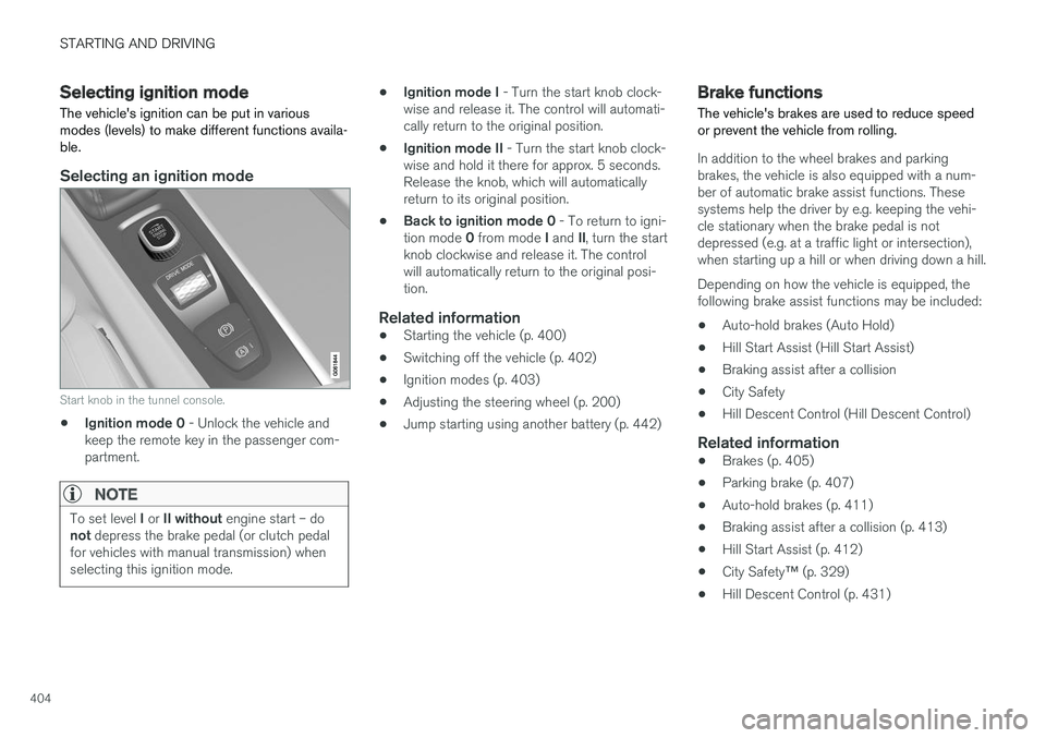
Start knob in the tunnel console.
• Ignition mode 0
- Unlock the vehicle and
keep the remote key in the passenger com- partment.
NOTE
To set level I or II without engine start – do
not depress the brake pedal (or clutch pedal
for vehicles with manual transmission) when selecting this ignition mode.
• Ignition mode I
- Turn the start knob clock-
wise and release it. The control will automati- cally return to the original position.
• Ignition mode II
- Turn the start knob clock-
wise and hold it there for approx. 5 seconds.Release the knob, which will automaticallyreturn to its original position.
• Back to ignition mode 0
- To return to igni-
tion mode 0 from mode I and II, turn the start
knob clockwise and release it. The controlwill automatically return to the original posi-tion.
Related information
• Starting the vehicle (p. 400)
• Switching off the vehicle (p. 402)
• Ignition modes (p. 403)
• Adjusting the steering wheel (p. 200)
• Jump starting using another battery (p. 442)
Brake functions
The vehicle's brakes are used to reduce speed or prevent the vehicle from rolling.
In addition to the wheel brakes and parking brakes, the vehicle is also equipped with a num-ber of automatic brake assist functions. Thesesystems help the driver by e.g. keeping the vehi-cle stationary when the brake pedal is notdepressed (e.g. at a traffic light or intersection),when starting up a hill or when driving down a hill. Depending on how the vehicle is equipped, the following brake assist functions may be included:
• Auto-hold brakes (Auto Hold)
• Hill Start Assist (Hill Start Assist)
• Braking assist after a collision
• City Safety
• Hill Descent Control (Hill Descent Control)
Related information
•
Brakes (p. 405)
• Parking brake (p. 407)
• Auto-hold brakes (p. 411)
• Braking assist after a collision (p. 413)
• Hill Start Assist (p. 412)
• City Safety
™ (p. 329)
• Hill Descent Control (p. 431)
Page 451 of 662

STARTING AND DRIVING
}}
449
Disabling the automatic check
The automatic light check can be disabled in the center display. 1.Tap
Settings in the Top view.
2. Tap
My CarLights and Lighting.
3. Deselect
Automatic Trailer Lamp Check.
Manual check
If the automatic check has been disabled, the check can be started manually. 1.Tap
Settings in the Top view.
2. Tap
My CarLights and Lighting.
3. Select
Manual Trailer Lamp Check.
> The light check will begin. Get out of the vehicle to perform the check.
Related information
• Driving with a trailer (p. 445)
Towing using a towline
This section refers to one vehicle being towed behind another using a towline.
Before towing another vehicle, check applicable speed limit regulations.
Preparations and towing
CAUTION
Note that the vehicle must always be towed with the wheels rolling forward.
• Do not tow a vehicle with automatictransmission at a speed greater than80 km/h (50 mph) or for a distancegreater than 80 km (50 miles).
WARNING
•
Ignition mode
II must be active – all air-
bags are deactivated in ignition mode I.
• Always have the remote key in the vehicle when it is towed.
WARNING
The brake and steering servos do not work when the engine is off – it takesabout 5 times more pressure on the brakepedal and steering requires much more effortthan normal. 1. Turn on the hazard warning flashers.
2. Attach the towline to the towing eyelet.3.
Put the vehicle in ignition mode II – without
pressing the brake pedal, turn the start knob clockwise and hold it there for about4 seconds. Release the knob, which willautomatically return to its original position.
4. Move the gear selector to neutral ( N) and
release the parking brake. If the battery charge level is too low, it may not be possible to release the parking brake.Connect an auxiliary battery to the vehicle ifthe battery is discharged.
> The towing vehicle can now start driving.
5. Keep the towline taut when the towing vehi- cle slows down by applying light pressure to the brake pedal. This will help avoid jarringmovements.
6. Be prepared to apply the brakes to stop the vehicle.
Jump startingDo not tow the vehicle to start the engine. Use anauxiliary battery if the start battery's charge levelis so low that the engine cannot be started.
Page 543 of 662
WHEELS AND TIRES
}}
* Option/accessory.541
1. Turn on the vehicle's hazard warning flashers
if a wheel change must be performed in an area with traffic.
2. Apply the parking brake and put the gear selector in P.
For vehicles with
Leveling Control* : If the
vehicle is equipped with pneumatic suspen- sion, this must be switched off before the vehicle is lifted with the jack *.
3. Take out the jack *, lug wrench * and tool for
removing the plastic covers, which are stowed in the foam block.
Tool for removing the plastic covers on the wheel bolts.
4. Place chocks in front of and behind the wheels that are still on the ground. For exam- ple, use heavy wooden blocks or largestones. 5.
Using the lug wrench *, screw the towing eye
into place as far as possible according to theinstructions.
CAUTION
The towing eyelet must be screwed into the lug wrench * as far as possible.
6. Remove the plastic covers from the wheel
bolts using the designated tool.
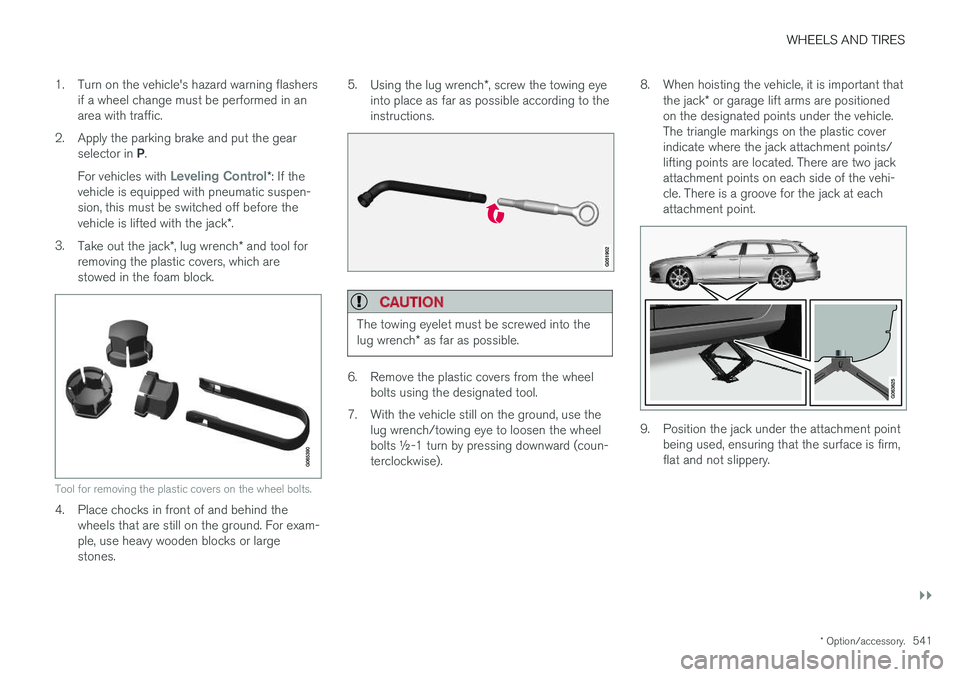
7. With the vehicle still on the ground, use the lug wrench/towing eye to loosen the wheel bolts ½-1 turn by pressing downward (coun-terclockwise). 8. When hoisting the vehicle, it is important that
the jack * or garage lift arms are positioned
on the designated points under the vehicle.The triangle markings on the plastic coverindicate where the jack attachment points/lifting points are located. There are two jackattachment points on each side of the vehi-cle. There is a groove for the jack at eachattachment point.
9. Position the jack under the attachment point being used, ensuring that the surface is firm, flat and not slippery.
Page 562 of 662
||
LOADING, STORAGE AND PASSENGER COMPARTMENT
* Option/accessory.
560
The illustration is generic – the design may vary.
To lock the glove compartment:
Insert the key into the lock on the glove com- partment.
Turn the key 90 degrees clockwise.
Remove the key from the lock.
–To unlock, perform the above steps in reverse.
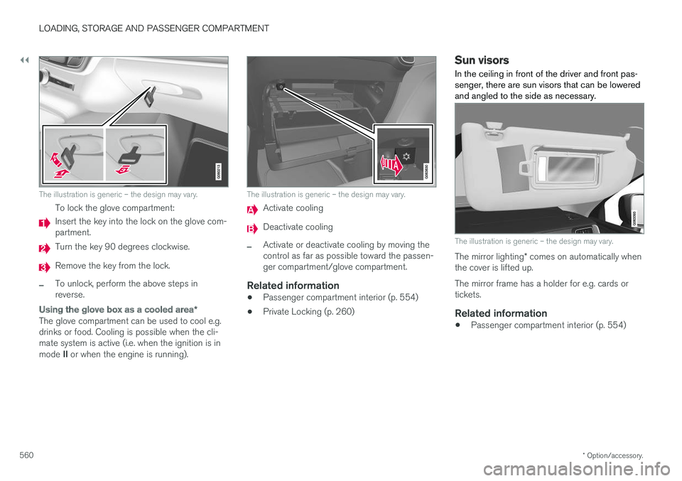
Using the glove box as a cooled area *
The glove compartment can be used to cool e.g. drinks or food. Cooling is possible when the cli-mate system is active (i.e. when the ignition is in mode II or when the engine is running).
The illustration is generic – the design may vary.
Activate cooling
Deactivate cooling
–Activate or deactivate cooling by moving the control as far as possible toward the passen-ger compartment/glove compartment.
Related information
• Passenger compartment interior (p. 554)
• Private Locking (p. 260)
Sun visors In the ceiling in front of the driver and front pas- senger, there are sun visors that can be loweredand angled to the side as necessary.
The illustration is generic – the design may vary.
The mirror lighting
* comes on automatically when
the cover is lifted up. The mirror frame has a holder for e.g. cards or tickets.
Related information
• Passenger compartment interior (p. 554)
Page 583 of 662
MAINTENANCE AND SERVICE
}}
581
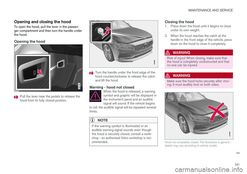
Opening and closing the hood To open the hood, pull the lever in the passen- ger compartment and then turn the handle underthe hood.
Opening the hood
Pull the lever near the pedals to release the hood from its fully closed position.
Turn the handle under the front edge of the hood counterclockwise to release the catchand lift the hood.
Warning - hood not closedWhen the hood is released, a warningsymbol and graphic will be displayed inthe instrument panel and an audiblesignal will sound. If the vehicle begins
to roll, the audible signal will be repeated severaltimes.
NOTE
If the warning symbol is illuminated or an audible warning signal sounds even thoughthe hood is securely closed, consult a work-shop - an authorized Volvo workshop is rec-ommended.
Closing the hood1. Press down the hood until it begins to close under its own weight.
2. When the hood reaches the catch at the handle in the front edge of the vehicle, press down on the hood to close it completely.
WARNING
Risk of injury! When closing, make sure that the hood is completely unobstructed and thatno one can be injured.
WARNING
Make sure the hood locks securely after clos- ing. It must audibly lock on both sides.
Hood not completely closed. The illustration is generic - details may vary according to vehicle model.
Page 595 of 662
MAINTENANCE AND SERVICE
}}
593
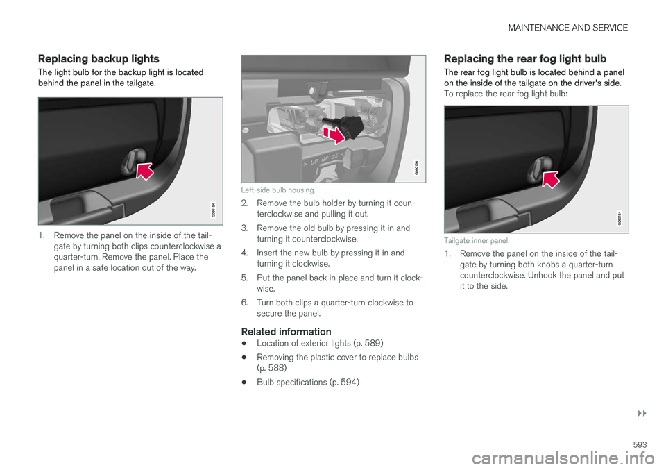
Replacing backup lights The light bulb for the backup light is located behind the panel in the tailgate.
1. Remove the panel on the inside of the tail-gate by turning both clips counterclockwise a quarter-turn. Remove the panel. Place thepanel in a safe location out of the way.
Left-side bulb housing.
2. Remove the bulb holder by turning it coun-terclockwise and pulling it out.
3. Remove the old bulb by pressing it in and turning it counterclockwise.
4. Insert the new bulb by pressing it in and turning it clockwise.
5. Put the panel back in place and turn it clock- wise.
6. Turn both clips a quarter-turn clockwise to secure the panel.
Related information
• Location of exterior lights (p. 589)
• Removing the plastic cover to replace bulbs (p. 588)
• Bulb specifications (p. 594)
Replacing the rear fog light bulb The rear fog light bulb is located behind a panel on the inside of the tailgate on the driver's side.
To replace the rear fog light bulb:
Tailgate inner panel.
1. Remove the panel on the inside of the tail-
gate by turning both knobs a quarter-turn counterclockwise. Unhook the panel and putit to the side.
Page 596 of 662
||
MAINTENANCE AND SERVICE
594
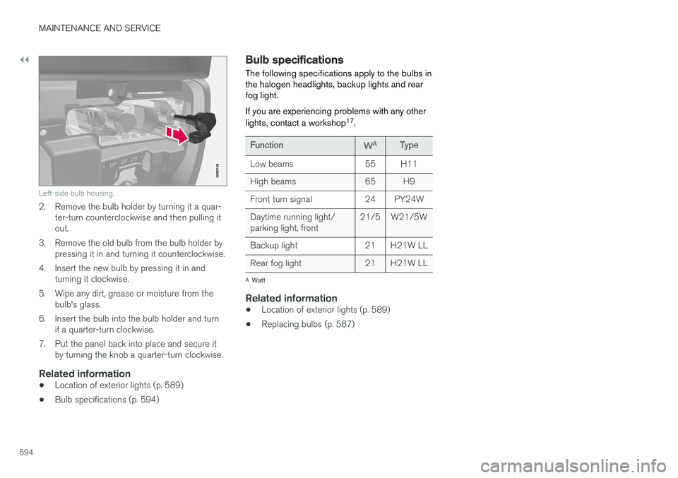
Left-side bulb housing.
2. Remove the bulb holder by turning it a quar-ter-turn counterclockwise and then pulling it out.
3. Remove the old bulb from the bulb holder by pressing it in and turning it counterclockwise.
4. Insert the new bulb by pressing it in and turning it clockwise.
5. Wipe any dirt, grease or moisture from the bulb's glass.
6. Insert the bulb into the bulb holder and turn it a quarter-turn clockwise.
7. Put the panel back into place and secure it by turning the knob a quarter-turn clockwise.
Related information
• Location of exterior lights (p. 589)
• Bulb specifications (p. 594)
Bulb specifications The following specifications apply to the bulbs in the halogen headlights, backup lights and rearfog light. If you are experiencing problems with any other lights, contact a workshop 17
.
FunctionWAType
Low beams 55 H11
High beams 65 H9
Front turn signal 24 PY24WDaytime running light/ parking light, front 21/5 W21/5W
Backup light 21 H21W LL
Rear fog light 21 H21W LL
A Watt
Related information
• Location of exterior lights (p. 589)
• Replacing bulbs (p. 587)