2018 VOLVO V90 CROSS COUNTRY brake
[x] Cancel search: brakePage 450 of 662

||
STARTING AND DRIVING
* Option/accessory.
448 When Trailer Stability Assist is activated, the
ESC symbol is
displayed in the instrument panel.
Related information
• Driving with a trailer (p. 445)
• Electronic Stability Control (p. 268)
Checking trailer lights
When connecting a trailer, make sure that all of the lights on the trailer are functioning beforestarting to drive.
Trailer turn signals and brake lightsIf one or more of the turn signals or brake lights on the trailer is not working, a symbol and mes-sage will be displayed in the instrument panel.The other lights on the trailer must be checkedmanually by the driver before the vehicle is driven.
SymbolMessage
•Trailer turn indicator Right
turn indicator malfunction
•Trailer turn indicator Left
turn indicator malfunction
•Trailer brake light Malfunc-
tion
If any of the trailer's turn signal lights is not work- ing, the turn signal symbol in the instrumentpanel will also flash more quickly than normal.
Trailer rear fog lightWhen a trailer is connected, the vehicle's rear foglight may not illuminate and rear fog light func-tionality is instead transferred to the trailer. If thisis the case, check to see if the trailer is equippedwith a rear fog light before activating the vehicle's fog lights when driving with a trailer to helpensure safe operation.
Checking trailer lights
*
Automatic check
When the trailer has been connected to the vehi- cle's electrical system, its lights can be checkedby automatically activating them. This functionhelps the driver check that the trailer's lights arefunctioning correctly before starting to drive. In order to perform this check, the engine must be turned off.
1. When a trailer is connected to the towbar,
the message
Automatic Trailer Lamp
Check will appear in the instrument panel.
2. Acknowledge the message by pressing the O button on the right-side steering wheel
keypad.
> The light check will begin.
3. Get out of the vehicle to perform the check. > All of the lights on the trailer will beginflashing, and then illuminate separately one at a time.
4. Visually check that all of the trailer's lights are functioning correctly.
5. After a short time, all of the trailer's lights will start flashing again.
> The light check is completed.
Page 451 of 662

STARTING AND DRIVING
}}
449
Disabling the automatic check
The automatic light check can be disabled in the center display. 1.Tap
Settings in the Top view.
2. Tap
My CarLights and Lighting.
3. Deselect
Automatic Trailer Lamp Check.
Manual check
If the automatic check has been disabled, the check can be started manually. 1.Tap
Settings in the Top view.
2. Tap
My CarLights and Lighting.
3. Select
Manual Trailer Lamp Check.
> The light check will begin. Get out of the vehicle to perform the check.
Related information
• Driving with a trailer (p. 445)
Towing using a towline
This section refers to one vehicle being towed behind another using a towline.
Before towing another vehicle, check applicable speed limit regulations.
Preparations and towing
CAUTION
Note that the vehicle must always be towed with the wheels rolling forward.
• Do not tow a vehicle with automatictransmission at a speed greater than80 km/h (50 mph) or for a distancegreater than 80 km (50 miles).
WARNING
•
Ignition mode
II must be active – all air-
bags are deactivated in ignition mode I.
• Always have the remote key in the vehicle when it is towed.
WARNING
The brake and steering servos do not work when the engine is off – it takesabout 5 times more pressure on the brakepedal and steering requires much more effortthan normal. 1. Turn on the hazard warning flashers.
2. Attach the towline to the towing eyelet.3.
Put the vehicle in ignition mode II – without
pressing the brake pedal, turn the start knob clockwise and hold it there for about4 seconds. Release the knob, which willautomatically return to its original position.
4. Move the gear selector to neutral ( N) and
release the parking brake. If the battery charge level is too low, it may not be possible to release the parking brake.Connect an auxiliary battery to the vehicle ifthe battery is discharged.
> The towing vehicle can now start driving.
5. Keep the towline taut when the towing vehi- cle slows down by applying light pressure to the brake pedal. This will help avoid jarringmovements.
6. Be prepared to apply the brakes to stop the vehicle.
Jump startingDo not tow the vehicle to start the engine. Use anauxiliary battery if the start battery's charge levelis so low that the engine cannot be started.
Page 454 of 662
STARTING AND DRIVING
* Option/accessory.
452
Recovery
This section refers to transporting the vehicle with a tow truck or similar vehicle.
Call a professional towing service for assistance. In certain conditions, the towing eyelet can be used to pull the vehicle onto a flatbed tow truck. For vehicles equipped with leveling control *:
If the vehicle is equipped with pneumatic suspen- sion, this feature must be turned off before thevehicle is lifted onto a tow truck. Turning off thefunction in the center display. 1. Tap
Settings in the Top view.
2. Tap
My CarParking Brake and
Suspension.
3. Select
Disable Leveling Control.
The vehicle's location and ground clearance determine if it can be lifted onto a tow truck. Ifthe incline of the tow truck is too steep or if theground clearance under the vehicle is insufficient,attempting to pull it up may result in damage. Inthis case, the vehicle should only be lifted withthe tow truck's lifting equipment.
WARNING
No person or object should be behind the tow truck when the vehicle is lifted onto the bedof the truck.
CAUTION
The towing eyelet is only intended for towing on roads, and must not be used to pull vehi-
cles from ditches or any similar purpose involving severe strain. Call a tow truck forprofessional assistance.
CAUTION
Note that the vehicle must always be towed with the wheels rolling forward.
Related information
• Attaching and removing the towing eyelet (p. 450)
HomeLink®
*12
HomeLink ®
13
is a programmable remote control,
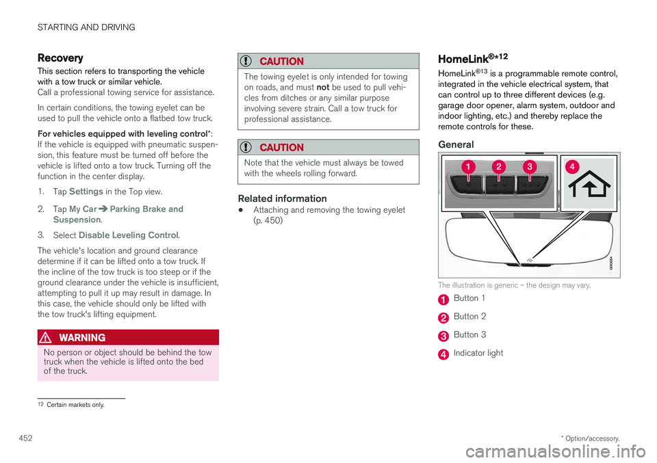
integrated in the vehicle electrical system, that can control up to three different devices (e.g.garage door opener, alarm system, outdoor andindoor lighting, etc.) and thereby replace theremote controls for these.
General
The illustration is generic – the design may vary.
Button 1
Button 2
Button 3
Indicator light
12 Certain markets only.
Page 542 of 662
||
WHEELS AND TIRES
* Option/accessory.
540
Related information
• Removing a wheel (p. 540)
• Installing a wheel (p. 542)
Removing a wheel
Instructions for removing a wheel when chang- ing wheels. Wheel changes must always be car-ried out correctly.
CAUTION
• When not in use, the jack
* should be kept
in its storage compartment under the cargo compartment floor.
• The jack provided with your vehicle isintended to be used only in temporary sit-uations such as changing wheels in theevent of a flat tire. Only the jack thatcame with your particular model shouldbe used to lift the vehicle. If the vehicleneeds to be lifted more frequently or for aprolonged period, using a garage jack orhoist is recommended. Always follow thisdevice's instructions for use.
WARNING
•Apply the parking brake and put the gear selector in the Park (
P) position.
• Block the wheels standing on the ground, use rigid wooden blocks or large stones.
• Check that the jack is not damaged, thethreads are properly lubricated and it isfree from dirt.
• Be sure the jack is on a firm, level, non-slippery surface and that it is upright andnot leaning.
• The jack must correctly engage in thejack attachment.
• No objects should be placed between thebase of the jack and the ground, orbetween the jack and the attachment baron the vehicle.
• Never let anyone remain in the vehiclewhen it is raised on a jack.
• If a tire must be changed near passingtraffic, make sure all passengers move toa safe location.
• Use a jack intended for the vehicle whenchanging a tire. For any other job, usestands to support the vehicle.
• Never crawl under or allow any part ofyour body to be extended under a vehiclesupported by a jack.
Page 543 of 662
WHEELS AND TIRES
}}
* Option/accessory.541
1. Turn on the vehicle's hazard warning flashers
if a wheel change must be performed in an area with traffic.
2. Apply the parking brake and put the gear selector in P.
For vehicles with
Leveling Control* : If the
vehicle is equipped with pneumatic suspen- sion, this must be switched off before the vehicle is lifted with the jack *.
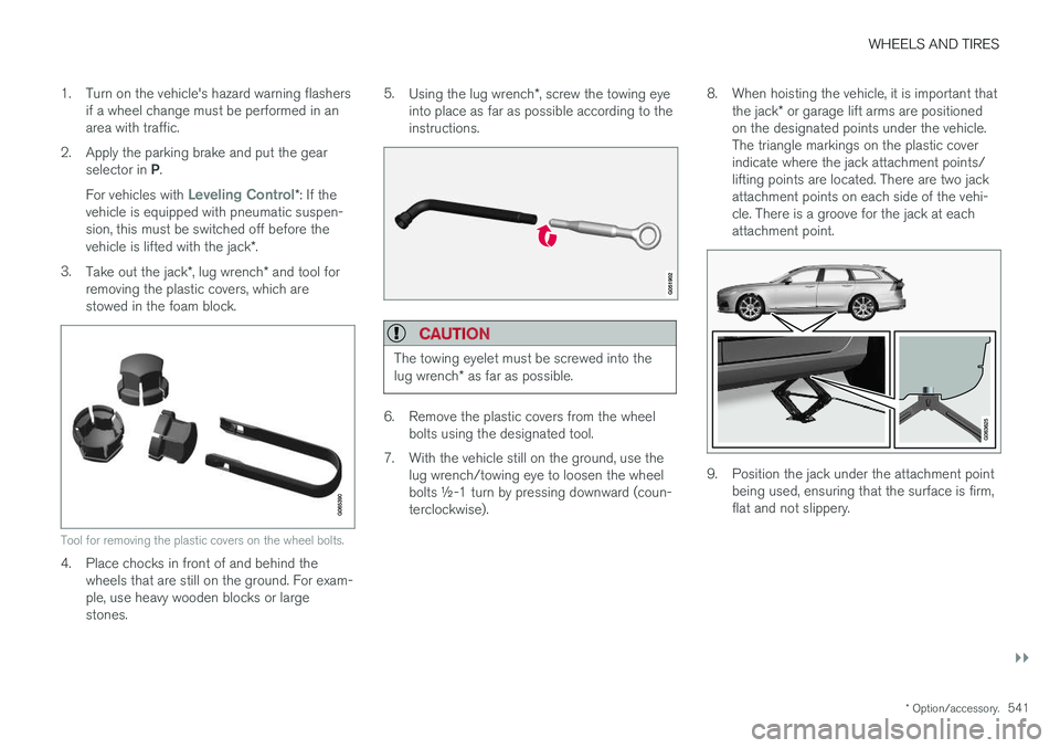
3. Take out the jack *, lug wrench * and tool for
removing the plastic covers, which are stowed in the foam block.
Tool for removing the plastic covers on the wheel bolts.
4. Place chocks in front of and behind the wheels that are still on the ground. For exam- ple, use heavy wooden blocks or largestones. 5.
Using the lug wrench *, screw the towing eye
into place as far as possible according to theinstructions.
CAUTION
The towing eyelet must be screwed into the lug wrench * as far as possible.
6. Remove the plastic covers from the wheel
bolts using the designated tool.
7. With the vehicle still on the ground, use the lug wrench/towing eye to loosen the wheel bolts ½-1 turn by pressing downward (coun-terclockwise). 8. When hoisting the vehicle, it is important that
the jack * or garage lift arms are positioned
on the designated points under the vehicle.The triangle markings on the plastic coverindicate where the jack attachment points/lifting points are located. There are two jackattachment points on each side of the vehi-cle. There is a groove for the jack at eachattachment point.
9. Position the jack under the attachment point being used, ensuring that the surface is firm, flat and not slippery.
Page 544 of 662
||
WHEELS AND TIRES
* Option/accessory.
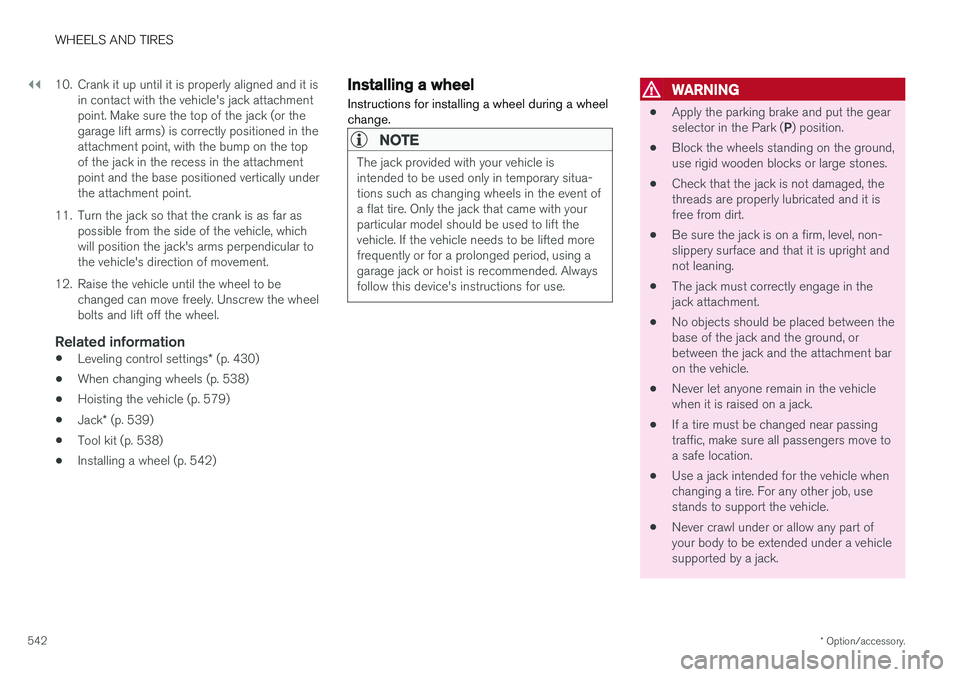
542 10. Crank it up until it is properly aligned and it is
in contact with the vehicle's jack attachment point. Make sure the top of the jack (or thegarage lift arms) is correctly positioned in theattachment point, with the bump on the topof the jack in the recess in the attachmentpoint and the base positioned vertically underthe attachment point.
11. Turn the jack so that the crank is as far as possible from the side of the vehicle, whichwill position the jack's arms perpendicular tothe vehicle's direction of movement.
12. Raise the vehicle until the wheel to be changed can move freely. Unscrew the wheelbolts and lift off the wheel.
Related information
• Leveling control settings
* (p. 430)
• When changing wheels (p. 538)
• Hoisting the vehicle (p. 579)
• Jack
* (p. 539)
• Tool kit (p. 538)
• Installing a wheel (p. 542)
Installing a wheel
Instructions for installing a wheel during a wheel change.
NOTE
The jack provided with your vehicle is intended to be used only in temporary situa-tions such as changing wheels in the event ofa flat tire. Only the jack that came with yourparticular model should be used to lift thevehicle. If the vehicle needs to be lifted morefrequently or for a prolonged period, using agarage jack or hoist is recommended. Alwaysfollow this device's instructions for use.
WARNING
• Apply the parking brake and put the gear selector in the Park (
P) position.
• Block the wheels standing on the ground, use rigid wooden blocks or large stones.
• Check that the jack is not damaged, thethreads are properly lubricated and it isfree from dirt.
• Be sure the jack is on a firm, level, non-slippery surface and that it is upright andnot leaning.
• The jack must correctly engage in thejack attachment.
• No objects should be placed between thebase of the jack and the ground, orbetween the jack and the attachment baron the vehicle.
• Never let anyone remain in the vehiclewhen it is raised on a jack.
• If a tire must be changed near passingtraffic, make sure all passengers move toa safe location.
• Use a jack intended for the vehicle whenchanging a tire. For any other job, usestands to support the vehicle.
• Never crawl under or allow any part ofyour body to be extended under a vehiclesupported by a jack.
Page 548 of 662
||
WHEELS AND TIRES
546
CAUTION
Snow chains can be used on the vehicle, with the following restrictions:• Volvo recommends not using snowchains on wheel dimensions larger than18 inches.
• Always follow the manufacturer's installa-tion instructions carefully. Install chainsas tightly as possible and retighten peri-odically.
• Only put snow chains on the front wheels(also applies to all-wheel drive vehicles).
• If accessory, aftermarket or "custom"tires and wheels with different dimen-sions than the original tires and wheelsare used, snow chains in some casesmay NOT be used. Sufficient distancebetween the chains and brakes, suspen-sion and body components must bemaintained.
• Check local regulations regarding the useof snow chains before installing.
• Never exceed the snow chain manufac-turer's specified maximum speed limit.Under no circumstances should youexceed 50 km/h (30 mph).
• Avoid bumps, holes or sharp turns whendriving with snow chains.
• Avoid driving on surfaces without snow as this wears out both the snow chains andthe tires.
• The handling of the vehicle can beadversely affected when driving withchains. Avoid fast or sharp turns as wellas locked wheel braking.
• Some types of strap-on chains affectbrake components and therefore mustNOT be used.
Consult a Volvo retailer for more information about snow chains.
Related information
•
Winter driving (p. 435)
Tire sealing system12
The temporary tire sealing system can be used to seal a puncture in a tire or to check andadjust the pressure in the tire. Models equipped with a spare wheel 13
do not
have the tire sealing system.
The tire sealing system consists of a compressor and a bottle containing sealing compound. Thesealing functions as a temporary repair.
NOTE
The sealing compound effectively seals tires with punctures in the tread but may not beable to fully seal tires with punctures in thesidewall. Do not use the tire sealing systemon tires with large tears, cracks or similardamage.
NOTE
The compressor is intended for temporary tire sealing and is approved by Volvo.
LocationThe tire sealing system is located in a foam block under the floor of the cargo compartment.
Page 563 of 662
LOADING, STORAGE AND PASSENGER COMPARTMENT
}}
* Option/accessory.561
Cargo compartment The vehicle has a flexible cargo compartment that makes it possible to carry and secure largeobjects.
The cargo capacity of the vehicle can be consid- erably increased by folding down the rear seatbackrests. Use the load anchoring eyelets or gro-cery bag holders to help secure objects in place, and the retractable cargo compartment cover * to
help conceal objects in the cargo compartment. The towing eyelet and tire sealing system, or the temporary spare tire *, are located under the
cargo compartment floor.
Related information
• Loading recommendations (p. 561)
• Grocery bag holders (p. 562)
• Load anchoring eyelets (p. 563)
• Installing and removing the cargo compart-ment cover
* (p. 564)
Loading recommendations
There are a number of things to consider when carrying loads in or on the vehicle.
Load-carrying capacity is determined by the vehi- cle's curb weight. The total weight of all passen-gers and any installed accessories reduces thevehicle's load-carrying capacity by the corres-ponding amount.
WARNING
The vehicle's driving characteristics change depending on the weight and position of theload.
Loading in the trunk and cargo compartment
• Position objects so they are pressing against the rear seat backrests.
• Distribute the load evenly.
• Heavy objects should be positioned as lowas possible. Avoid placing heavy objects onfolded-down seat backrests.
• Cover sharp corners with a soft cloth or simi-lar to help prevent damage to the upholstery.
• Use the load anchoring eyelets and tension-ing straps or similar to secure all objects.
WARNING
In a head-on collision at a speed of 50 km/h (30 mph), an unsecured object weighing 20kg (44 pounds) can reach a projectile weightequivalent to 1000 kg (2200 pounds).
WARNING
If objects are loaded higher than the upper edge of the side windows, leave a 10 cm (4in.) space between the objects and the win-dow. Objects placed closer to this couldimpede the function of the inflatable curtainconcealed inside the headlining.
WARNING
Always secure the load. Otherwise, it may shift during heavy braking and injure people in thevehicle. Cover sharp edges and sharp corners with something soft. Turn off the engine and apply the parking brake when loading/unloading long objects.Otherwise, it is possible for the load to reachthe gear lever or gear selector and move it toa drive position – which could cause the vehi-cle to begin rolling.