Page 1 of 502
Front view
Fig. 2 Front view of the vehicle.
Key to Fig. 2
Windscreen:
Vehicle identification number Technical data
Windscreen wipers WipersWiper blades
Rain/light sensor in the area of the interior mirror Rain/light sensorCaring for and cleaning the
vehicle exterior
Sensor for lighting functions Caring for and cleaning the vehicle exterior
Bonnet opening lever In the engine compartment
Behind the Volkswagen badge: radar sensor for assist systems Caring for and cleaning the
vehicle exterior
Sensors for assist systems Caring for and cleaning the vehicle exteriorDriver assist systems
Behind a cover: mounting for towing eye Tow-starting or towing
Lights in the bumper LightsChanging bulbs
Page 6 of 502
In the engine compartment
Fuse box cover Changing fuses
Lever for adjusting the steering column position Steering wheel
Light switch Vehicle lighting
Turn signal and main beam lever Vehicle lighting
With switches and buttons for the driver assist systems Button for driver assist systemsDriver
assist systems
Vents Heating and air conditioning system
Instrument cluster Instrument cluster
With warning and indicator lamps Symbols in instrument cluster
Lever for wipers and washers Wipers
With buttons for operating the menus Instrument cluster
Controls on the multifunction steering wheel:
Operating driver assist systems Operating using the multifunction steering wheelDriver assist
systems
Audio, navigation
Opening the telephone menu or accepting telephone calls
Volume adjustment
Activating voice control (no function in some models)
Horn
Location of the driver front airbag Airbag system
Ignition lock Starting and stopping the engine
Pedals Pedals
Page 9 of 502

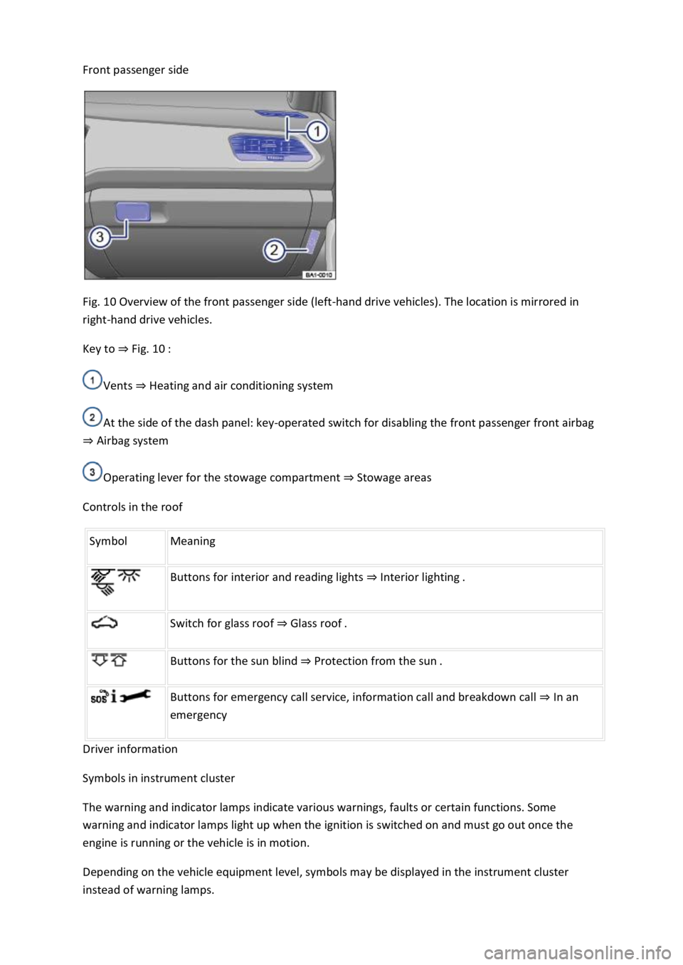
Front passenger side
Fig. 10 Overview of the front passenger side (left-hand drive vehicles). The location is mirrored in
right-hand drive vehicles.
Key to Fig. 10
Vents Heating and air conditioning system
At the side of the dash panel: key-operated switch for disabling the front passenger front airbag
Airbag system
Operating lever for the stowage compartment Stowage areas
Controls in the roof
Symbol Meaning
Buttons for interior and reading lights Interior lighting.
Switch for glass roof Glass roof.
Buttons for the sun blind Protection from the sun.
Buttons for emergency call service, information call and breakdown call In an
emergency
Driver information
Symbols in instrument cluster
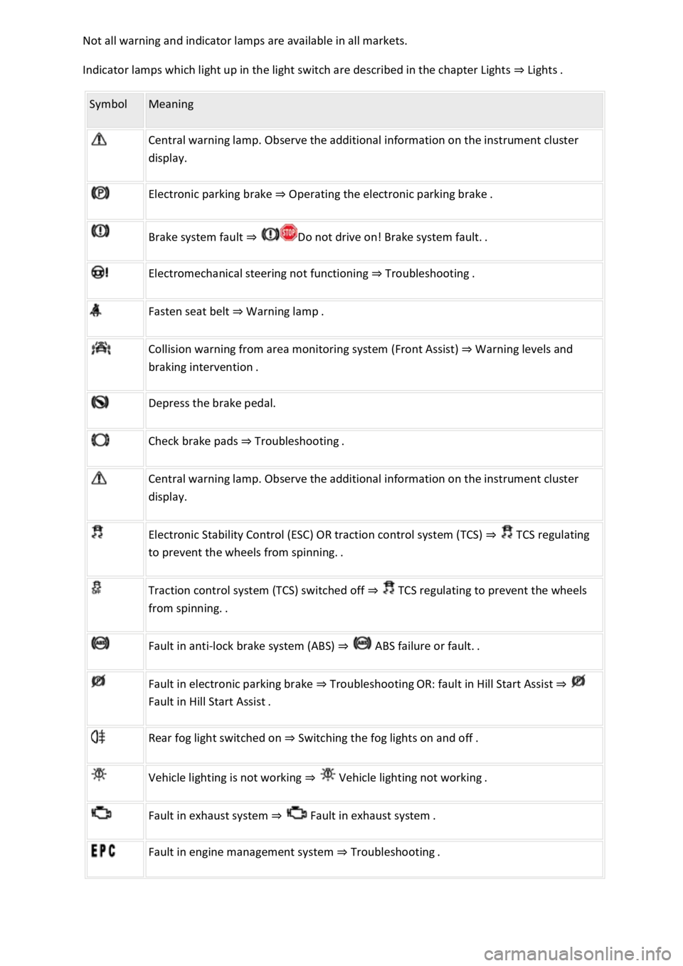
The warning and indicator lamps indicate various warnings, faults or certain functions. Some
warning and indicator lamps light up when the ignition is switched on and must go out once the
engine is running or the vehicle is in motion.
Depending on the vehicle equipment level, symbols may be displayed in the instrument cluster
instead of warning lamps.
Page 10 of 502

Indicator lamps which light up in the light switch are described in the chapter Lights Lig
Symbol Meaning
Central warning lamp. Observe the additional information on the instrument cluster
display.
Electronic parking brake Operating the electronic parking brake.
Brake system fault
Electromechanical steering not functioning Troubleshooting.
Fasten seat belt Warning lamp.
Collision warning from area monitoring system (Front Assist) Warning levels and
Depress the brake pedal.
Check brake pads Troubleshooting.
Central warning lamp. Observe the additional information on the instrument cluster
display.
Electronic Stability Control (ESC) OR traction control system (TCS) TCS regulating
to
Traction control system (TCS) switched off TCS regulating to prevent the wheels
Fault in anti-lock brake system (ABS)
Fault in electronic parking brake TroubleshootingOR: fault in Hill Start Assist
Rear fog light switched on Switching the fog lights on and off.
Vehicle lighting is not working
Fault in exhaust system Fault
Fault in engine management system Troubleshooting.
Page 14 of 502

Introduction
This chapter contains information on the followingsubjects:
Analogue instrument cluster
Rev counter
Digital instrument cluster (Active Info Display)
Displays
Instrument cluster menus
Service menu
Driving data display (multifunction display)
Warning and information messages
Driver Alert System (recommendation for rest breaks)
Dynamic Road Sign Display (Sign Assist)
Time
Lap timer
Fuel gauge
Coolant temperature display
Service interval display
The vehicle is equipped either with an analogue or a digital instrument cluster (Active Info Display).
When you start the engine after the 12-volt battery has been totally discharged or changed, you may
find that system settings (time, date, personal convenience settings and programming) have been
changed or deleted. Check and correct the settings as necessary once the 12-volt vehicle battery has
been sufficiently charged.
WARNING
Accidents and injuries can occur if the driver is distracted.
Never press the buttons on the instrument cluster while the vehicle is in motion.
Any settings for the instrument cluster display and displays in the Infotainment system should be
made only when the vehicle is stationary in order to reduce the risk of accidents and serious injuries.
Page 15 of 502
Fig. 11 Analogue instrument cluster in the dash panel.
First read and observe the introductoryinformation and safety warnings
Descriptions of the instruments Fig. 11
Rev counter (running engine speed in revolutions x 1,000 per minute) Rev counter
Coolant temperature displayCoolant temperature display
DisplaysDisplays
Reset, set and display button.
Speedometer.
Fuel gaugeFuel gauge
Rev counter
First read and observe the introductory information and safety warnings
Rev counter
The start of the red zone on the rev counter indicates the maximum engine speed that may be used
in each gear when the engine is warm and after it has been run in properly. You should change up a
gear or move the selector lever to D/S (or lift your foot off the accelerator) before the needle
reaches the red zone
Page 16 of 502
When the engine is cold, avoid high engine speeds, driving at full throttle and overloading the
engine.
The needle on the rev counter should only briefly point into the red area, as engine damage may
otherwise be incurred.
Changing up a gear early will help to save fuel and reduce engine noise.
Digital instrument cluster (Active Info Display)
First read and observe the introductory information and safety warnings
The Active Info Display is a digital instrument cluster with high-resolution TFT colour display. To
complement the standard dials such as the rev counter and speedometer, users can choose from
various "information profiles" to view additional data.
Fig. 12 Active Info Display in the dash panel
Descriptions of the instruments Fig. 12
Rev counter (running engine speed in revolutions x 1,000 per minute) Rev counter
Current gear / selector lever positionManual gearbox: selecting a gearor DSG
Page 19 of 502
Personalisation
Open doors, bonnet and boot lid
The instrument cluster display indicates if any doors, the engine compartment or boot lid are open
once the vehicle has been unlocked, and while the vehicle is in motion. In some cases, a signal tone
is also given. Different instrument cluster designs may have different displays.
Selector lever positions (DSG