Page 278 of 672
2784-5. Using the driving support systems
■Screen description
The rear view monito r system screen will be displayed if the sh ift
lever is shifted to R while the engine switch is in “ON” positi on.
Vehicle width guide lines
Displays a guide path when the vehicle is being backed straight up.
The displayed width is wider than the actual vehicle width.
Vehicle center guide lines
This lines indicate the estimated vehicle center on the ground.
Distance guide line
Displays a point approximately 1.5 ft. (0.5 m) (red) from the e dge of the
bumper.
Distance guide line
Displays a point approximately 3 ft. (1 m) (blue) from the edge of the
bumper.
Using the rear view monitor system
1
2
3
4
Page 279 of 672
2794-5. Using the driving support systems
4
Driving
■Area displayed on screen
The rear view monitor system
displays an image of the view
from the bumper of the rear
area of the vehicle.
The image adjustment proce-
dure for the rear view monitor
system screen is the same as
the procedure for adjusting the
screen. (P. 3 3 3 )
• The area displayed on the
screen may vary according to
vehicle orientation conditions.
• Objects which are close to either corner of the bumper or under
the bumper cannot be dis-
played.
• The camera uses a special lens. The distance of the image that
appears on the screen differs
from the actual distance.
• Items which are located higher than the camera may not be disp layed
on the monitor.
■
Rear view monitor system camera
The camera for the rear view
monitor system is located as
shown in the illustration.
Rear view monitor system precautions
Corners of bumper
Page 281 of 672

2814-5. Using the driving support systems
4
Driving
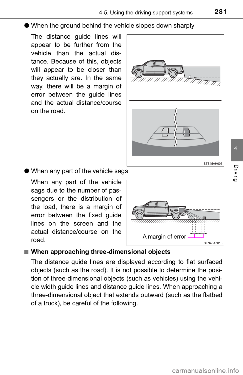
●When the ground behind the ve hicle slopes down sharply
The distance guide lines will
appear to be further from the
vehicle than the actual dis-
tance. Because of this, objects
will appear to be closer than
they actually are. In the same
way, there will be a margin of
error between the guide lines
and the actual distance/course
on the road.
● When any part of the vehicle sags
When any part of the vehicle
sags due to the number of pas-
sengers or the distribution of
the load, there is a margin of
error between the fixed guide
lines on the screen and the
actual distance/course on the
road.
■When approaching thre e-dimensional objects
The distance guide lines are displayed according to flat surfac ed
objects (such as the road). It i s not possible to determine the posi-
tion of three-dimensional object s (such as vehicles) using the vehi-
cle width guide lines and distance guide lines. When approachin g a
three-dimensional object that ext ends outward (such as the flatbed
of a truck), be careful of the following.
A margin of error
Page 284 of 672

2844-5. Using the driving support systems
WARNING
■When using the rear view monitor system
The rear view monitor system is a supplemental device intended to assist
the driver when backing up. When backing up, be sure to visually check all
around the vehicle both directly and using the mirrors before proceeding.
Observe the following precautions to avoid an accident that cou ld result in
death or serious injuries.
● Never depend on the rear view monitor system entirely when back ing up.
The image and the position of the guide lines displayed on the screen may
differ from the actual state.
Use caution, just as you would when backing up any vehicle.
● Be sure to back up slowly, depressing the brake pedal to contro l vehicle
speed.
● The instructions given are only guide lines.
When and how much to turn the steering wheel will vary according to traf-
fic conditions, road surface conditions, vehicle condition, etc . when park-
ing. It is necessary to be fully aware of this before using the rear view
monitor system.
● When parking, be sure to check that the parking space will acco mmodate
your vehicle before maneuvering into it.
● Do not use the rear view monitor system in the following cases:
• On icy or slick road surfaces, or in snow
• When using tire chains or emergency tires
• When the tailgate is not closed completely
• On roads that are not flat or straight, such as curves or slop es.
● In low temperatures, the screen may darken or the image may bec ome
faint. The image could distort when the vehicle is moving, or y ou may
become unable to see the image on the screen. Be sure to visual ly check
all around the vehicle both directly and using the mirrors befo re proceed-
ing.
● If the tire sizes are changed, the position of the fixed guide lines displayed
on the screen may change.
● The camera uses a special lens. The distances between objects a nd
pedestrians that appear in the image displayed on the screen will differ
from the actual distances. ( P. 280)
Page 286 of 672

2864-5. Using the driving support systems
BSM (Blind Spot Monitor)
The Blind Spot Monitor is a system that has 2 functions;
● The Blind Spot Monitor function
Assists the driver in making t he decision when changing lanes
● The Rear Cross Traffic Alert function
Assists the driver when backing up
These functions use same sensors.
Multi-information display
Turning the BSM function/RCTA function on/off. ( P. 287)
Outside rear view mirror indicators
Blind Spot Monitor function:
When a vehicle is detected in a blind spot of the outside rear view mir-
rors or approaching rapidly from behind into a blind spot, the outside
rear view mirror indicator on the detected side will illuminate. If the turn
signal lever is operated toward the detected side, the outside rear view
mirror indicator will flash.
Rear Cross Traffic Alert function:
When a vehicle approaching from the right or left at the rear of the vehi-
cle is detected, both outside rear view mirror indicators will flash.
: If equipped
Summary of the Blind Spot Monitor
1
2
Page 287 of 672

2874-5. Using the driving support systems
4
Driving
Rear Cross Traffic Alert buzzer (Rear Cross Traffic Alert function
only)
When a vehicle approaching from the right or left rear of the v ehicle is
detected, a buzzer sounds from behind the left-hand rear pillar .
“BSM” indicator
When the BSM function is turned on, the indicator illuminates.
“RCTA” indicator
When the RCTA function is turned on, the indicator illuminates.
The BSM (Blind Spot Monitor) function and RCTA (Rear Cross Traf fic
Alert) function can be enabled/d isabled on the multi-information dis-
play as following:
Press “ ” or “” of meter control sw itches and select .
Press “ ” or “ ” of meter control switches and select “BSM” or
“RCTA”, and press to select the desired setting (on/off).
The BSM (Blind Spot Monitor) outside rear view mirror indicator s
brightness can be changed on the m ulti-information display as follow-
ing:
Press “ ” or “” of meter control sw itches and select .
Press “ ” or “ ” of meter control switches and select “Vehicle
Settings”, and then press .
Press “ ” or “ ” of meter control switches and select “BSM
Brightness”, and then press to select the desired setting
(bright/dim).
Turning the BSM function/RCTA function on/off
Changing the BSM indicator brightness
3
4
5
1
2
1
2
3
Page 288 of 672

2884-5. Using the driving support systems
Press “” or “” of meter control sw itches and select .
Press “ ” or “ ” of meter control switches and select “Vehicle
Settings”, and then press .
Press “ ” or “ ” of meter control switches and select “RCTA Vol-
ume”, and then press to sel ect the desired setting.
The buzzer volume cha nges with each press.
■The outside rear view mirror indicators visibility
When under strong sunlight, the outside rear view mirror indica tor may be dif-
ficult to see.
■ Rear Cross Traffic Alert buzzer hearing
Rear Cross Traffic Alert function may be difficult to hear over noises such as
high audio volume.
■ When there is a malfunction in the Blind Spot Monitor system
If a system malfunction is detected due to any of the following reasons, warn-
ing messages will be displayed: ( P. 557, 558)
● There is a malfunction with the sensors
● The sensors have become dirty
● The outside temperature is extremely high or low
● The sensor voltage has become abnormal
■ Certification for the Blind Spot Monitor system
For vehicles sold in the U.S.A.
FCC ID: OAYSRR3A
This device complies with part 15 of the FCC Rules. Operation is subject to
the following three conditions:
(1) This device may not cause harmful interference, and
(2) this device must accept any interference received, includin g interference
that may cause undesired operation.
FCC Warning
Changes or modifications not expressly approved by the party re sponsible for
compliance could void the user’s authority to operate the equip ment.
Changing the Rear Cross Traffic Alert warning buzzer volume
1
2
3
Page 304 of 672

3044-5. Using the driving support systems
■Turning off TRAC, VSC and Trailer Sway Control systems
2WD models and 2WD mode on 4WD models
To turn the TRAC, VSC and Trailer Sway Control systems off, sto p the vehi-
cle completely, and then press and hold
for more than 3 seconds
while the AUTO LSD system is activated. ( P. 299)
4H mode on 4WD models
To turn the TRAC, VSC and Trailer Sway Control systems off, press and
hold
for more than 3 seconds while the vehicle is stopped.
The VSC off and “TRAC OFF” indicator light will come on.
Press
again to turn the system back on.
■ When the VSC or TRAC system is turned off by pressing the VSC o ff
switch
On vehicles with pre-collision system, pre-collision brake assi st and pre-colli-
sion braking will also be disabled. The PCS warning light will come on and
the message will be shown on the multi-information display. ( P. 563)
■ When the “TRAC OFF” indicator light comes on even if VSC off sw itch
has not been pressed.
TRAC cannot be operated. Contact your Toyota dealer.
■ Operating conditions of hill-start assist control
When the following four conditions are met, the hill-start assi st control will
operate:
● The shift lever is in a position other than P or N (when starting off forward/
backward on an upward incline)
● The vehicle is stopped
● The accelerator pedal is not depressed
● The parking brake is not engaged
■ Automatic system cancelation of hill-start assist control
The hill-start assist control will turn off in any of the follo wing situations:
The shift lever is shifted to P or N
● The accelerator pedal is depressed
● The parking brake is engaged
● 2 seconds at maximum elapsed after the brake pedal is released