Page 112 of 660
1122. Instrument cluster
AVENSIS_OM_OM20C79E_(EE)
Settings display
Select to change the meter display settings and the operation set-
tings of some vehicle functions. (P. 1 1 4 )
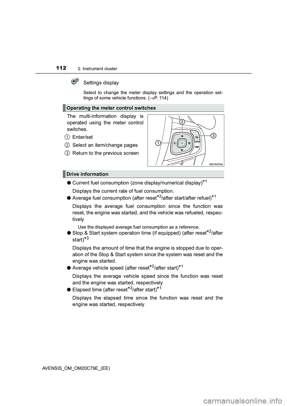
The multi-information display is
operated using the meter control
switches.
Enter/set
Select an item/change pages
Return to the previous screen
●Current fuel consumption (zone display/numerical display)
*1
Displays the current rate of fuel consumption.
●Average fuel consumption (after reset
*2/after start/after refuel)*1
Displays the average fuel consumption since the function was
reset, the engine was started, and the vehicle was refueled, respec-
tively
Use the displayed average fuel consumption as a reference.
●Stop & Start system operation time (if equipped) (after reset*2/after
start)
*3
Displays the amount of time that the engine is stopped due to oper-
ation of the Stop & Start system since the system was reset and the
engine was started.
●Average vehicle speed (after reset
*2/after start)*1
Displays the average vehicle speed since the function was reset
and the engine was started, respectively
●Elapsed time (after reset
*2/after start)*1
Displays the elapsed time since the function was reset and the
engine was started, respectively
Operating the meter control switches
1
2
3
Drive information
Page 113 of 660
1132. Instrument cluster
2
Instrument cluster
AVENSIS_OM_OM20C79E_(EE)
●Distance (driving range/after start)*1
Displays the estimated maximum distance that can be driven with
the quantity of fuel remaining and the distance driven after the
engine was started, respectively
• This distance is computed based on your average fuel consump-
tion. As a result, the actual distance that can be driven may differ
from that displayed.
• When only a small amount of fuel is added to the tank, the dis-
play may not be updated.
When refueling, turn the engine switch off. If the vehicle is refu-
eled without turning the engine switch off, the display may not be
updated.
●Display off
A blank screen is displayed.
*1: Can be registered to Drive information 1 and 2. (P. 114)
*2: Resetting procedures:
• Select a function to be reset using the meter control switches and then
press and hold to reset.
• If there is more than one function that can be reset, check boxes will be
displayed next to those functions.
*3: Can be registered to Drive information 3. (P. 114)
Page 116 of 660
1162. Instrument cluster
AVENSIS_OM_OM20C79E_(EE)
WARNING
■The information display at low temperatures
Allow the interior of the vehicle to warm up before using the liquid crystal
information display. At extremely low temperatures, the display monitor may
respond slowly, and display changes may be delayed.
For example, there is a lag between the driver’s shifting and the new gear
number appearing on the display. This lag could cause the driver to down-
shift again, causing rapid and exce ssive engine braking and possibly an
accident resulting in death or injury.
■ Cautions during setting up the display
As the engine needs to be running during setting up the display, ensure that
the vehicle is parked in a place with adequate ventilation. In a closed area
such as a garage, exhaust gases including harmful carbon monoxide (CO)
may collect and enter the vehicle. This may lead to death or a serious
health hazard.
Page 137 of 660
1373-2. Opening, closing and locking the doors
3
Operation of each component
AVENSIS_OM_OM20C79E_(EE)■
Setting and canceling the functions (vehicles without naviga-
tion system or multimedia system)
To switch between setting and canceling, follow the procedure
below.
Close all the doors, and turn the engine switch to “ON” position
(vehicles without smart entry & start system) or IGNITION ON
mode (vehicles with smart entry & start system).
Perform within 10 seconds.
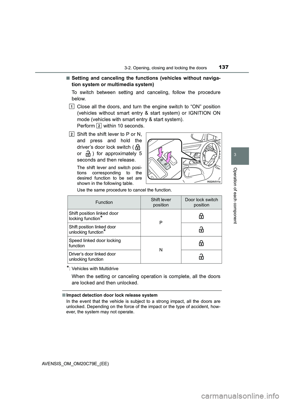
Shift the shift lever to P or N,
and press and hold the
driver’s door lock switch (
or ) for approximately 5
seconds and then release.
The shift lever and switch posi-
tions corresponding to the
desired function to be set are
shown in the following table.
Use the same procedure to cancel the function.
*: Vehicles with Multidrive
When the setting or canceling operation is complete, all the doors
are locked and then unlocked.
■Impact detection door lock release system
In the event that the vehicle is subject to a strong impact, all the doors are
unlocked. Depending on the force of the impact or the type of accident, how-
ever, the system may not operate.
1
2
2
FunctionShift lever
positionDoor lock switch
position
Shift position linked door
locking function
*PShift position linked door
unlocking function
*
Speed linked door locking
function
NDriver’s door linked door
unlocking function
Page 138 of 660
1383-2. Opening, closing and locking the doors
AVENSIS_OM_OM20C79E_(EE)
■ Conditions affecting operation
Vehicles without smart entry & start system
P. 123
Vehicles with smart entry & start system
P. 152
■ Customization
Settings (e.g. automatic door locking and unlocking system) can be changed.
(Customizable features P. 629)
WARNING
■To prevent an accident
Observe the following precautions while driving the vehicle.
Failing to do so may result in a door opening and an occupant falling out,
resulting in death or serious injury.
● Ensure that all doors are properly closed.
● Do not pull the inside handle of the doors while driving.
Be especially careful for the driver’s door, as the door may be opened
even if the inside lock button is in locked position.
● Set the rear door child-protector locks when children are seated in the rear
seat.
Page 173 of 660
1733-3. Adjusting the seats
3
Operation of each component
AVENSIS_OM_OM20C79E_(EE)
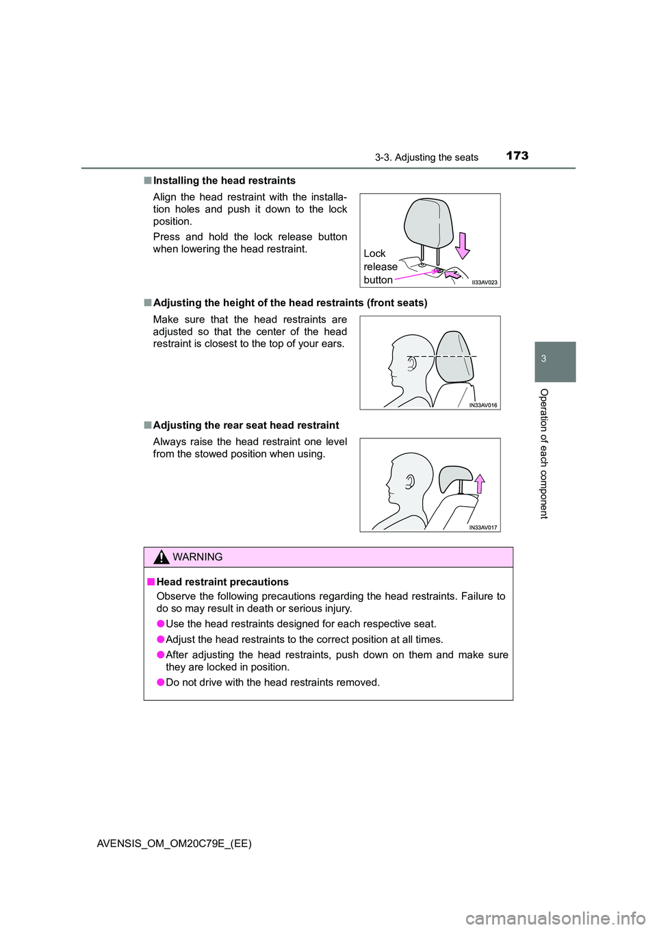
■ Installing the head restraints
■ Adjusting the height of the head restraints (front seats)
■ Adjusting the rear seat head restraint
Align the head restraint with the installa-
tion holes and push it down to the lock
position.
Press and hold the lock release button
when lowering the head restraint.
Make sure that the head restraints are
adjusted so that the center of the head
restraint is closest to the top of your ears.
Always raise the head restraint one level
from the stowed position when using.
WARNING
■ Head restraint precautions
Observe the following precautions regarding the head restraints. Failure to
do so may result in death or serious injury.
● Use the head restraints designed for each respective seat.
● Adjust the head restraints to the correct position at all times.
● After adjusting the head restraints, push down on them and make sure
they are locked in position.
● Do not drive with the head restraints removed.
Lock
release
button
Page 177 of 660
1773-4. Adjusting the steering wheel and mirrors
3
Operation of each component
AVENSIS_OM_OM20C79E_(EE)
Manual anti-glare inside rear view mirror
Reflected light from the headlights of vehicles behind can be reduced
by operating the lever.
Normal position
Anti-glare position
Auto anti-glare inside rear view mirror
Responding to the level of brightness of the headlights of vehicles
behind, the reflected light is automatically reduced.
Changing automatic anti-glare
function mode ON/OFF
When the automatic anti-glare
function is in ON mode, the indica-
tor illuminates.
The function will set to ON mode
each time the engine switch is
turned to “ON” position (vehicles
without smart entry & start system)
or IGNITION ON mode (vehicles
with smart entry & start system).
Pressing the button turns the function to OFF mode. (The indicator also
turns off.)
Anti-glare function
1
2
Indicator
Page 184 of 660
1843-5. Opening and closing the windows
AVENSIS_OM_OM20C79E_(EE)
If you release the switch while the window is moving, start again from the
beginning. If the window continues to close but then re-open slightly even
after performing the above procedure correctly, have the vehicle inspected by
any authorized Toyota retailer or Toyota authorized repairer, or any reliable
repairer.
WARNING
Observe the following precautions.
Failing to do so may result in death or serious injury.
■ When closing the windows
● The driver is responsible for all the power window operations, including the
operation for the passengers. In order to prevent accidental operation,
especially by a child, do not let a child operate the power windows. It is
possible for children and other passengers to have body parts caught in
the power window. Also, when riding with a child, it is recommended to use
the window lock switch. ( P. 182)
● Check to make sure that all passengers do not have any part of their body
in a position where it could be caught when a window is being operated.
● When exiting the vehicle, turn the engine switch to the “LOCK” position
(vehicles without smart entry & start system) or off (vehicles with smart
entry & start system), carry the key and exit the vehicle along with the
child. There may be accidental operation, due to mischief, etc., that may
possibly lead to an accident.
■ Jam protection function
● Never use any part of your body to intentionally activate the jam protection
function.
● The jam protection function may not work if something gets caught just
before the window fully closes.