2018 SUBARU CROSSTREK electrical
[x] Cancel search: electricalPage 53 of 474
(54,1)
北米Model "A1320BE-C" EDITED: 2017/ 10/ 10
&System monitorsA diagnostic system continually monitors
the readiness of the seatbelt pretensioner
while the vehicle is being driven. The
seatbelt pretensioners share the control
module with the SRS airbag system.
Therefore, if any malfunction occurs in a
seatbelt pretensioner, the SRS airbag
system warning light will illuminate. For
details, refer to“SRS airbag system
monitors”F1-66.&System servicing
WARNING
.When discarding a seatbelt re-
tractor assembly or scrapping
the entire vehicle damaged by a
collision, consult your SUBARU
dealer.
.Tampering with or disconnecting
the system’s wiring could result
in accidental activation of the
seatbelt pretensioner and/or
SRS airbag or could make the
system inoperative, which may
result in serious injury. Do not
use electrical test equipment on
any circuit related to the seatbelt
pretensioner and SRS airbag sys-
tems. For required servicing ofthe seatbelt pretensioner, con-
sult your nearest SUBARU deal-
er.
CAUTION
The sensors and SRS airbag control
modules are located in the following
locations.
.Front sub sensors: on both the
right and left side at the front of
the vehicle
.Front door impact sensors: on
both front doors
.Satellite safing sensor: under the
rear center seat
.SRS airbag control module (in-
cluding the impact sensors): un-
der the center of the instrument
panel
If you need service or repair in those
areas or near the front seatbelt
retractors, have the work performed
by your authorized SUBARU dealer.NOTEIf the front or side part of the vehicle is
damaged in an accident to the extent
that the seatbelt pretensioner does notoperate, contact your SUBARU dealer
as soon as possible.
&Precautions against vehicle
modificationAlways consult your SUBARU dealer if you
want to install any accessory parts to your
vehicle.
CAUTION
Do not perform any of the following
modifications. Such modifications
can interfere with proper operation
of the seatbelt pretensioners.
.Attachment of any equipment
(bush bar, winches, snow plow,
skid plate, etc.) other than genu-
ine SUBARU accessory parts to
the front end.
.Modification of the suspension
system or front end structure.
.Installation of a tire of different
size and construction from the
tires specified on the vehicle
placard attached to the driver’s
door pillar or specified for indivi-
dual vehicle models in this Own-
er’s Manual.
Seat, seatbelt and SRS airbags/Seatbelt pretensioners
1-24
Page 79 of 474
(80,1)
北米Model "A1320BE-C" EDITED: 2017/ 10/ 10
case, contact your SUBARU dealer
immediately.
CAUTION
Electrical devices, such as cell
phones, laptops, portable music
players, or electronic games, espe-
cially when connected to the acces-
sory power outlet and placed on the
front passenger’s seat or used by
the person sitting in the front pas-
senger’s seat, may affect the opera-
tion of the occupant detection sys-
tem. If either of the following situa-
tions occurs when using an electro-
nic device in the vehicle, at first try
to relocate that device to avoid it
creating any interference.
.The SRS airbag system warning
light illuminates.
.The front passenger’s frontal air-
bag ON and OFF indicators oper-
ate erratically.
If the device continues to cause
interference, the use of that device
in the vehicle should be discontin-
ued.
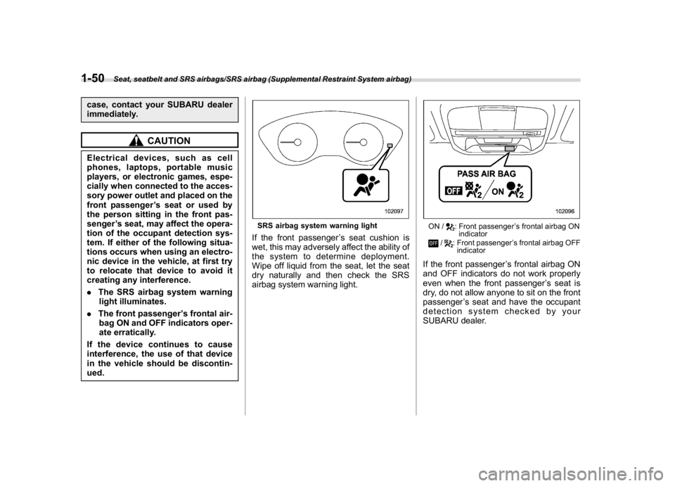
SRS airbag system warning lightIf the front passenger’s seat cushion is
wet, this may adversely affect the ability of
the system to determine deployment.
Wipe off liquid from the seat, let the seat
dry naturally and then check the SRS
airbag system warning light.
ON /
: Front passenger’s frontal airbag ON
indicator
/
: Front passenger’s frontal airbag OFF
indicator
If the front passenger’s frontal airbag ON
and OFF indicators do not work properly
even when the front passenger’s seat is
dry, do not allow anyone to sit on the front
passenger’s seat and have the occupant
detection system checked by your
SUBARU dealer.
Seat, seatbelt and SRS airbags/SRS airbag (Supplemental Restraint System airbag)
1-50
Page 96 of 474

(97,1)
北米Model "A1320BE-C" EDITED: 2017/ 10/ 10
The following components are monitored
by the indicator:
.Front sub sensor
.Airbag control module (including im-
pact sensor and rollover sensor)
.Frontal airbag module
–Driver’s side
–Front passenger’s side
.Knee airbag module (driver’s side)
.Side airbag sensor
.Front door impact sensor
.Side airbag module
.Curtain airbag sensor
.Curtain airbag module
.Satellite safing sensor (under the rear
center seat)
.Seatbelt pretensioner (driver’s side)
.Seatbelt pretensioner and adaptive
force limiter (front passenger’s side)
.Lap belt pretensioner (front passen-
ger’s side)
.Seatbelt buckle switch (front passen-
ger’s side)
.Front passenger’s occupant detection
system sensor
.Front passenger’s occupant detection
control module
.Front passenger’s frontal airbag ON
and OFF indicator
.All related wiring
WARNING
If the warning light exhibits any of
the following conditions, there may
be a malfunction in the seatbelt
pretensioners and/or SRS airbag
system.
.Flashing or flickering of the warn-
ing light
.No illumination of the warning
light when the ignition switch is
first turned to the“ON”position
.Continuous illumination of the
warning light
.Illumination of the warning light
while driving
Immediately take your vehicle to
your nearest SUBARU dealer to
have the system checked. Unless
checked and properly repaired, the
seatbelt pretensioners and/or SRS
airbag will not operate properly in
the event of a collision, which may
increase the risk of injury.
&SRS airbag system servicing
WARNING
.When discarding an airbag mod-
ule or scrapping the entire vehi-
cle damaged by a collision, con-
sult your SUBARU dealer.
.The SRS airbag has no user-
serviceable parts. Do not use
electrical test equipment on any
circuit related to the SRS airbag
system. For required servicing of
the SRS airbag, consult your
nearest SUBARU dealer. Tamper-
ingwithordisconnectingthe
system’s wiring could result in
accidental inflation of the SRS
airbag or could make the system
inoperative, which may result in
serious injury.
CAUTION
If you need service or repair in areas
indicated in the following list, have
the work performed by an author-
ized SUBARU dealer. The SRS air-
bag control module, impact sensors
and airbag modules are stored in
these areas.
–CONTINUED–
Seat, seatbelt and SRS airbags/SRS airbag (Supplemental Restraint System airbag)
1-67
1
Page 104 of 474
(107,1)
北米Model "A1320BE-C" EDITED: 2017/ 10/ 10
may damage the battery or
cause circuit malfunctions.
–Do not wash the access key
fob in an ultrasonic washer.
–Do not leave the access key
fob in humid or dusty loca-
tions. Doing so may cause
malfunctions.
–Keep the access key fob away
from magnetic sources.
–Do not leave the access key
fob near a personal computer
or home electrical appliance.
–Do not leave the access key
fob near a battery charger or
any electrical accessories.
–Do not apply metallic window
tint or attach metallic objects
to the windows.
–Do not fit non genuine acces-
sories or parts.
.If the access key fob is dropped,
the integrated emergency key in-
side may become loose. Be care-
ful not to lose the emergency key.
.When traveling in an airplane, do
not press the button of the ac-
cess key fob. If any button of the
access key fob is pressed, radio
waves are emitted and may affectthe operation of the airplane.
When carrying the access key
fob in a bag, take measures to
prevent the buttons from being
pressed accidentally.
NOTE.The operational/non-operational
setting for the keyless access function
can be changed. For the setting proce-
dure, refer to“Disabling keyless ac-
cess function”F2-12.
.For detailed information about the
operation method for the push-button
ignition switch while the keyless ac-
cess function is switched to the non-
operational mode, refer to“Access key
fob–if access key fob does not operate
properly”F9-17.
.The keyless access with push-but-
ton start system uses weak radio
waves. The status of the access key
fob and environmental conditions may
interfere with the communication be-
tween the access key fob and the
vehicle under the following conditions,
and it may not be possible to lock or
unlock the doors or start the engine.
–When operating near a facility
where strong radio waves are trans-
mitted, such as a broadcast stationand power transmission lines
–When products that transmit
radio waves are used, such as an
access key fob or a remote trans-
mitter key of another vehicle
–When carrying the access key fob
of your vehicle together with the
access key fob or the remote trans-
mitter of another vehicle
–When the access key fob is
placed near wireless communica-
tion equipment such as a cell phone
–When the access key fob is
placed near a metallic object
–When metallic accessories are
attached to the access key fob
–When carrying the access key fob
with electronic appliances such as a
laptop computer
–When the battery of the access
key fob is discharged
.The access key fob is always com-
municating with the vehicle and is
continuously using the battery.
Although the life of the battery varies
depending on the operating conditions,
it is approximately 1 to 2 years. If the
battery becomes fully discharged, re-
place it with a new one.
.If an access key fob is lost, it is
recommended that all of the remaining
access key fobs be reregistered. For
–CONTINUED–
Keys and doors/Keyless access with push-button start system
2-5
2
Page 137 of 474
(142,1)
北米Model "A1320BE-C" EDITED: 2017/ 10/ 10
Ignition switch (models with-
out“keyless access with
push-button start system”)
WARNING
.Never turn the ignition switch to
the“LOCK”position while the
vehicle is being driven or towed
because that will lock the steer-
ing wheel, preventing steering
control. And when the engine is
turned off, it takes a much greater
effort than usual to steer.
.Before leaving the vehicle, al-
ways remove the key from the
ignition switch for safety and
never allow an unattended child
to remain in the vehicle. Failure to
follow this procedure could re-
sult in injury to a child or others.
Children could operate the power
windows, the moonroof or other
controls or even make the vehicle
move.
CAUTION
Do not attach a large key holder or
key case to either key. If it banged
against your knees or hands while
you are driving, it could turn the
ignition switch from the“ON”posi-
tion to the“ACC”or“LOCK”posi-
tion, thereby stopping the engine.
Also, if the key is attached to a key
holder or to a large bunch of other
keys, centrifugal force may act on it
as the vehicle moves, resulting in
unwanted turning of the ignition
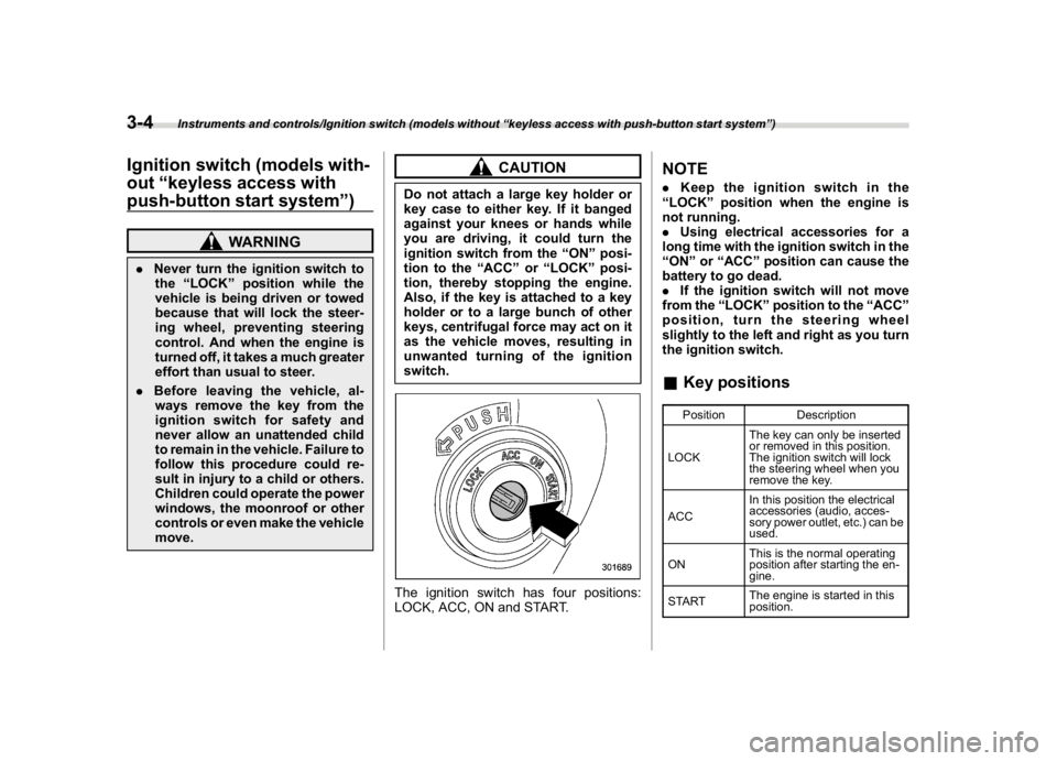
switch.The ignition switch has four positions:
LOCK, ACC, ON and START.
NOTE.Keep the ignition switch in the
“LOCK”position when the engine is
not running.
.Using electrical accessories for a
long time with the ignition switch in the
“ON”or“ACC”position can cause the
battery to go dead.
.If the ignition switch will not move
from the“LOCK”position to the“ACC”
position, turn the steering wheel
slightly to the left and right as you turn
the ignition switch.&Key positions
Position Description
LOCKThe key can only be inserted
or removed in this position.
The ignition switch will lock
the steering wheel when you
remove the key.
ACCIn this position the electrical
accessories (audio, acces-
sory power outlet, etc.) can be
used.
ONThis is the normal operating
position after starting the en-
gine.
STARTThe engine is started in this
position.
Instruments and controls/Ignition switch (models without“keyless access with push-button start system”)
3-4
Page 140 of 474
(145,1)
北米Model "A1320BE-C" EDITED: 2017/ 10/ 10
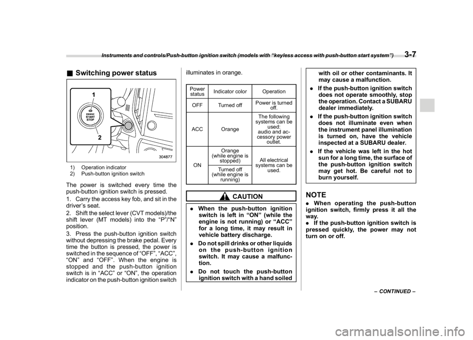
&Switching power status1) Operation indicator
2) Push-button ignition switchThe power is switched every time the
push-button ignition switch is pressed.
1. Carry the access key fob, and sit in the
driver’s seat.
2. Shift the select lever (CVT models)/the
shift lever (MT models) into the“P”/“N”
position.
3. Press the push-button ignition switch
without depressing the brake pedal. Every
time the button is pressed, the power is
switched in the sequence of“OFF”,“ACC”,
“ON”and“OFF”. When the engine is
stopped and the push-button ignition
switch is in“ACC”or“ON”, the operation
indicator on the push-button ignition switchilluminates in orange.
Power
statusIndicator color Operation
OFF Turned offPower is turned
off.
ACC OrangeThe following
systems can be
used:
audio and ac-
cessory power
outlet.
ONOrange
(while engine is
stopped)All electrical
systems can be
used. Turned off
(while engine is
running)
CAUTION
.When the push-button ignition
switch is left in“ON”(while the
engine is not running) or“ACC”
for a long time, it may result in
vehicle battery discharge.
.Do not spill drinks or other liquids
on the push-button ignition
switch. It may cause a malfunc-
tion.
.Do not touch the push-button
ignition switch with a hand soiledwith oil or other contaminants. It
may cause a malfunction.
.If the push-button ignition switch
does not operate smoothly, stop
the operation. Contact a SUBARU
dealer immediately.
.If the push-button ignition switch
does not illuminate even when
the instrument panel illumination
is turned on, have the vehicle
inspected at a SUBARU dealer.
.If the vehicle was left in the hot
sun for a long time, the surface of
the push-button ignition switch
may get hot. Be careful not to
burn yourself.
NOTE.When operating the push-button
ignition switch, firmly press it all the
way.
.If the push-button ignition switch is
pressed quickly, the power may not
turn on or off.
–CONTINUED–
Instruments and controls/Push-button ignition switch (models with“keyless access with push-button start system”)
3-7
3
Page 149 of 474
(154,1)
北米Model "A1320BE-C" EDITED: 2017/ 10/ 10
serious damage, which may not be
covered by your vehicle’s warranty.
If this light illuminates steadily or blinks
while the engine is running, it may indicate
that there is at least one problem or
potential problem somewhere in the emis-
sion control system.
!If the light illuminates steadily
If the light illuminates steadily while driving
or does not turn off after the engine starts,
an emission control system malfunction
has been detected.
You should have your vehicle checked by
an authorized SUBARU dealer immedi-
ately.NOTEThis light also illuminates when the fuel
filler cap is not tightened until it clicks.
If you have recently refueled your vehicle,
the cause of the CHECK ENGINE warning
light/malfunction indicator light illuminating
could be a loose or missing fuel filler cap.
Remove the cap and retighten it until it
clicks. Make sure nothing is interfering with
the sealing of the cap. Tightening the cap
will not make the CHECK ENGINE warn-
ing light turn off immediately. It may take
several driving trips. If the light does not
turn off, take your vehicle to your author-ized SUBARU dealer immediately.
!If the light is blinking
If the light is blinking while driving, an
engine misfire condition has been de-
tected which may damage the emission
control system.
To prevent serious damage to the emis-
sion control system, you should do the
following.
.Reduce vehicle speed.
.Avoid hard acceleration.
.Avoid steep uphill grades.
.Reduce the amount of cargo, if possi-
ble.
.Stop towing a trailer as soon as
possible.
The CHECK ENGINE warning light may
stop blinking and illuminate steadily after
several driving trips. You should have your
vehicle checked by an authorized
SUBARU dealer immediately.
&Coolant temperature
low indicator light/Cool-
ant temperature high
warning light
CAUTION
.After turning the ignition switch
to the“ON”position, if this
indicator light/warning light be-
haves in any of the following
ways, the electrical system may
be malfunctioning. Contact your
SUBARU dealer immediately for
an inspection.
–It remains blinking in RED.
–It remains illuminated in RED
for more than 2 seconds.
–It remains blinking in RED and
BLUE alternately.
.While driving, if this indicator
light/warning light behaves in
any of the following ways, take
the specified appropriate mea-
sure listed below.
–Blinking or illuminated in
RED:
Safely stop the vehicle as
soon as possible, and refer to
the emergency steps to take in
the case of engine overheat-
Instruments and controls/Warning and indicator
3-16
Page 150 of 474

(155,1)
北米Model "A1320BE-C" EDITED: 2017/ 10/ 10
ing. After that, have the sys-
tem checked by your nearest
SUBARU dealer. Refer to“En-
gine overheating”F9-12.
–Blinking in RED and BLUE
alternately:
The electrical system may be
malfunctioning. Contact your
SUBARU dealer for an inspec-
tion.
This coolant temperature low indicator
light/coolant temperature high warning
light has the following three functions.
.Illumination inBLUEindicates insuffi-
cient warming up of the engine
.Blinking inREDindicates that the
engine is close to overheating
.Illumination inREDindicates overheat-
ing condition of the engine
For a system check, this indicator light/
warning light illuminates inREDfor ap-
proximately 2 seconds when the ignition
switch is turned to the“ON”position. After
that, this indicator light/warning light
changes toBLUEand maintains illumina-
tion inBLUE. ThisBLUEilluminated light
turns off when the engine is warmed up
sufficiently.
If the engine coolant temperature in-creases over the specified range, the
indicator light/warning light blinks inRED.
At this time, the engine is close to over-
heating.
If the engine coolant temperature in-
creases further, the indicator light/warning
light illuminates inREDcontinuously. At
this time, the engine may be overheating.
When the indicator light/warning light
blinks inREDor illuminates inRED, safely
stop the vehicle as soon as possible, and
refer to the emergency steps to take in the
case of engine overheating. Refer to
“Engine overheating”F9-12. After that,
have the system checked by your nearest
SUBARU dealer.
Also, if the indicator light/warning light
often blinks inRED, the electrical system
may be malfunctioning. Contact your
SUBARU dealer for an inspection.
NOTEIf the engine is restarted after a certain
driving condition, this indicator light/
warning light may illuminate in RED.
However, this is not a malfunction if the
indicator light/warning light turns off
after a short time.
&Charge warning lightIf this light illuminates when the engine is
running, it may indicate that the charging
system is not working properly.
If the light illuminates while driving or does
not turn off after the engine starts, stop the
engine at the first safe opportunity and
check the alternator belt. If the belt is
loose, broken or if the belt is in good
condition but the light remains illuminated,
contact your nearest SUBARU dealer
immediately.&Oil pressure warning
lightIf this light illuminates when the engine is
running, it may indicate that the engine oil
pressure is low and the lubricating system
is not working properly.
If the light illuminates while driving or does
not turn off after the engine starts, stop the
engine at the first safe opportunity and
check the engine oil level. If the oil level is
low, add oil immediately. If the engine oil is
at the proper level but the light remains
illuminated, contact your nearest
SUBARU dealer immediately.
For details about checking the engine oil
level or adding the engine oil, refer to
“Engine oil”F11-8.
–CONTINUED–
Instruments and controls/Warning and indicator
3-17
3