2018 SUBARU CROSSTREK turn signal
[x] Cancel search: turn signalPage 209 of 474
(214,1)
北米Model "A1320BE-C" EDITED: 2017/ 10/ 10
&One-touch lane changerTo flash the turn signal and turn signal
indicator light three times, push the turn
signal lever up or down slightly and
immediately release it.NOTEThe operational/non-operational
setting of the one-touch lane changer
can be changed by a SUBARU dealer.
Contact the nearest SUBARU dealer for
details. For models with the combina-
tion meter display (color LCD), the
setting can also be changed by operat-
ing the combination meter display
(color LCD). For details, refer to“Vehi-
cle Setting”F3-41.
Wiper and washer
WARNING
In freezing weather, do not use the
windshield washer until the wind-
shield is sufficiently warmed by the
defroster.
Otherwise the washer fluid can
freeze on the windshield, blocking
your view.
CAUTION
.Do not operate the washer con-
tinuously for more than 10 sec-
onds, or when the washer fluid
tank is empty. This may cause
overheating of the washer motor.
Check the washer fluid level fre-
quently, such as at fuel stops.
.Do not operate the wipers when
the windshield or rear window is
dry. This may scratch the glass,
damage the blade rubbers and
might cause the wiper motor to
fail. Before operating the wiper
on a dry windshield or rear win-
dow, always use the windshield
washer..In freezing weather, be sure that
the blade rubbers are not frozen
to the windshield or rear window
before switching on the wipers.
Attempting to operate the wiper
withthebladesfrozentothe
window glass could cause not
only the blade rubbers to be
damaged but also might cause
the wiper motor to fail. If the blade
rubbers are frozen to the window
glass, be sure to operate the
defroster, windshield wiper dei-
cer (if equipped) or rear window
defogger before turning on the
wiper.
.If the wipers stop during opera-
tion because of ice or some other
obstruction on the window, this
might cause the wiper motor to
fail even if the wiper switch is
turned off. If this occurs,
promptly stop the vehicle in a
safe place, turn the ignition
switch to the“LOCK”/“OFF”po-
sition and clean the window glass
to allow proper wiper operation.
.Use clean water if windshield
washer fluid is unavailable. In
areas where water freezes in
winter, use SUBARU Windshield
Washer Fluid or the equivalent.
Instruments and controls/Wiper and washer
3-76
Page 215 of 474
(220,1)
北米Model "A1320BE-C" EDITED: 2017/ 10/ 10
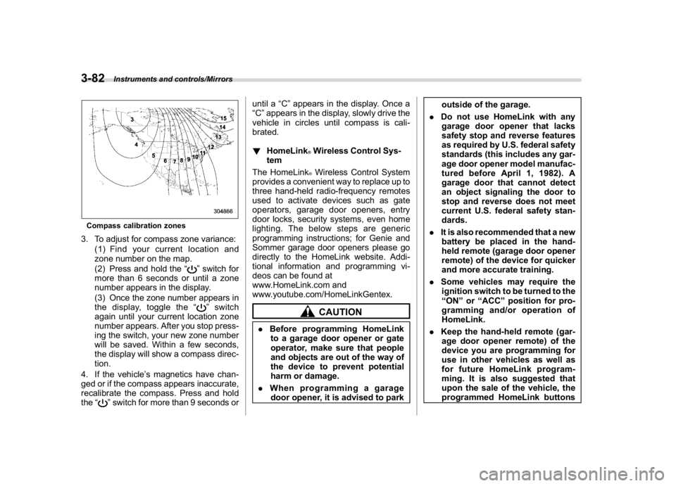
Compass calibration zones3. To adjust for compass zone variance:
(1) Find your current location and
zone number on the map.
(2) Press and hold the“
”switch for
more than 6 seconds or until a zone
number appears in the display.
(3) Once the zone number appears in
the display, toggle the“”switch
again until your current location zone
number appears. After you stop press-
ing the switch, your new zone number
will be saved. Within a few seconds,
the display will show a compass direc-
tion.
4. If the vehicle’s magnetics have chan-
ged or if the compass appears inaccurate,
recalibrate the compass. Press and hold
the“
”switch for more than 9 seconds oruntil a“C”appears in the display. Once a
“C”appears in the display, slowly drive the
vehicle in circles until compass is cali-
brated.
!HomeLink
®Wireless Control Sys-
tem
The HomeLink®Wireless Control System
provides a convenient way to replace up to
three hand-held radio-frequency remotes
used to activate devices such as gate
operators, garage door openers, entry
door locks, security systems, even home
lighting. The below steps are generic
programming instructions; for Genie and
Sommer garage door openers please go
directly to the HomeLink website. Addi-
tional information and programming vi-
deos can be found at
www.HomeLink.com and
www.youtube.com/HomeLinkGentex.CAUTION
.Before programming HomeLink
to a garage door opener or gate
operator, make sure that people
and objects are out of the way of
the device to prevent potential
harm or damage.
.When programming a garage
door opener, it is advised to parkoutside of the garage.
.Do not use HomeLink with any
garage door opener that lacks
safety stop and reverse features
as required by U.S. federal safety
standards (this includes any gar-
age door opener model manufac-
tured before April 1, 1982). A
garage door that cannot detect
an object signaling the door to
stop and reverse does not meet
current U.S. federal safety stan-
dards.
.It is also recommended that a new
battery be placed in the hand-
held remote (garage door opener
remote) of the device for quicker
and more accurate training.
.Some vehicles may require the
ignition switch to be turned to the
“ON”or“ACC”position for pro-
gramming and/or operation of
HomeLink.
.Keep the hand-held remote (gar-
age door opener remote) of the
device you are programming for
use in other vehicles as well as
for future HomeLink program-
ming. It is also suggested that
upon the sale of the vehicle, the
programmed HomeLink buttons
Instruments and controls/Mirrors
3-82
Page 221 of 474
(226,1)
北米Model "A1320BE-C" EDITED: 2017/ 10/ 10
WARNING
.When programming the
HomeLink
®Wireless Control Sys-
tem, you may be operating a
garage door opener or other
device. Make sure that people
and objects are out of the way of
the garage door or other device
to prevent potential harm or da-
mage.
.Do not use the HomeLink
®Wire-
less Control System with a gar-
age door opener that lacks the
safety stop and reverse feature
as required by applicable safety
standards. A garage door opener
which cannot detect an object,
signaling the door to stop and
reverse, does not meet these
safety standards. Using a garage
door opener without these fea-
tures increases risk of serious
injury or death. For more infor-
mation, consult the HomeLink
®
website at www.homelink.com or
call 1-800-355-3515.
&Outside mirrors!Convex mirror (passenger side)
WARNING
Objects look smaller in a convex
mirror and farther away than when
viewed in a flat mirror. Do not use the
convex mirror to judge the distance
of vehicles behind you when chan-
ging lanes. Use the inside mirror (or
glance backwards) to determine the
actual size and distance of objects
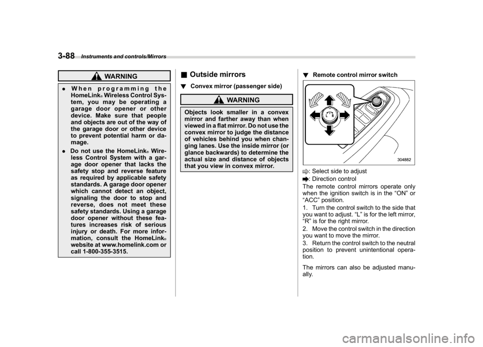
that you view in convex mirror.!Remote control mirror switch
: Select side to adjust: Direction control
The remote control mirrors operate only
when the ignition switch is in the“ON”or
“ACC”position.
1. Turn the control switch to the side that
you want to adjust.“L”is for the left mirror,
“R”is for the right mirror.
2. Move the control switch in the direction
you want to move the mirror.
3. Return the control switch to the neutral
position to prevent unintentional opera-
tion.
The mirrors can also be adjusted manu-
ally.
Instruments and controls/Mirrors
3-88
Page 284 of 474
(293,1)
北米Model "A1320BE-C" EDITED: 2017/ 10/ 10
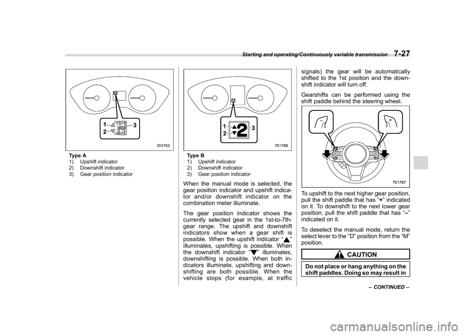
Type A
1) Upshift indicator
2) Downshift indicator
3) Gear position indicator
Type B
1) Upshift indicator
2) Downshift indicator
3) Gear position indicatorWhen the manual mode is selected, the
gear position indicator and upshift indica-
tor and/or downshift indicator on the
combination meter illuminate.
The gear position indicator shows the
currently selected gear in the 1st-to-7th-
gear range. The upshift and downshift
indicators show when a gear shift is
possible. When the upshift indicator“
”
illuminates, upshifting is possible. When
the downshift indicator“
”illuminates,
downshifting is possible. When both in-
dicators illuminate, upshifting and down-
shifting are both possible. When the
vehicle stops (for example, at trafficsignals) the gear will be automatically
shifted to the 1st position and the down-
shift indicator will turn off.
Gearshifts can be performed using the
shift paddle behind the steering wheel.
To upshift to the next higher gear position,
pull the shift paddle that has“+”indicated
on it. To downshift to the next lower gear
position, pull the shift paddle that has“–”
indicated on it.
To deselect the manual mode, return the
select lever to the“D”position from the“M”
position.
CAUTION
Do not place or hang anything on the
shift paddles. Doing so may result in
–CONTINUED–
Starting and operating/Continuously variable transmission
7-27
7
Page 299 of 474

(308,1)
北米Model "A1320BE-C" EDITED: 2017/ 10/ 10
never brake suddenly. Instead,
perform the following procedure.
Otherwise, an accident involving
serious vehicle damage and ser-
ious personal injury could occur.
(1) Keep driving straight ahead
while gradually reducing
speed.
(2) Slowly pull off the road to a
safe location.
(3) Check the pressure for all four
tires and adjust the pressure
to the COLD tire pressure
shown on the tire placard.
The tire placard is located on
the door pillar on the driver’s
side.
Even when the vehicle is driven a
very short distance, the tires get
warm and their pressures in-
crease accordingly. Be sure to
let the tires cool thoroughly be-
fore adjusting their pressures to
the standard values shown on the
tire placard. Refer to“Tires and
wheels”F11-21. The tire pres-
sure monitoring system does not
function when the vehicle is sta-
tionary. After adjusting the tire
pressures, increase the vehicle
speed to at least 20 mph (32 km/h)to start the TPMS rechecking of
the tire inflation pressures. If the
tire pressures are now above the
severe low pressure threshold,
the low tire pressure warning
light should turn off a few min-
utes later.
If this light still illuminates while
driving after adjusting the tire
pressure, a tire may have signifi-
cant damage and a fast leak that
causes the tire to lose air rapidly.
If you have a flat tire, replace it
with a spare tire as soon as
possible.
.When a spare tire is mounted or a
wheel rim is replaced without the
original pressure sensor/trans-
mitter being transferred, the low
tire pressure warning light will
illuminate steadily after blinking
for approximately one minute.
This indicates the TPMS is unable
to monitor all four road wheels.
Contact your SUBARU dealer as
soon as possible for tire and
sensor replacement and/or sys-
tem resetting.
.When a tire is repaired with liquid
sealant, the tire pressure warning
valve and transmitter may not
operate properly. If a liquid sea-lant is used, contact your nearest
SUBARU dealer or other qualified
service shop as soon as possi-
ble. Make sure to replace the tire
pressure warning valve and
transmitter when replacing the
tire. You may reuse the wheel if
there is no damage to it and if the
sealant residue is properly
cleaned off. Do not inject any tire
liquid or aerosol tire sealant into
the tires, as this may cause a
malfunction of the tire pressure
sensors. If the light illuminates
steadily after blinking for ap-
proximately one minute,
promptly contact a SUBARU
dealer to have the system in-
spected.
CAUTION
Do not place metal film or any metal
parts in the cargo area. This may
cause poor reception of the signals
from the tire pressure sensors, and
the tire pressure monitoring system
will not function properly.
Starting and operating/Tire pressure monitoring system (TPMS) (U.S.-spec. models)
7-42
Page 310 of 474
(319,1)
北米Model "A1320BE-C" EDITED: 2017/ 10/ 10
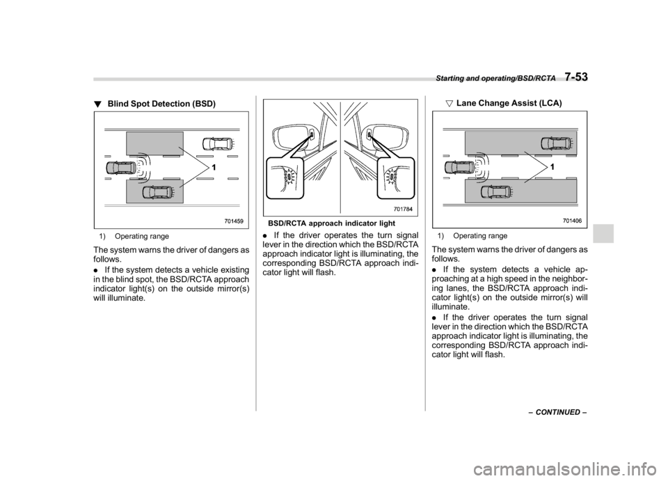
!Blind Spot Detection (BSD)1) Operating rangeThe system warns the driver of dangers as
follows.
.If the system detects a vehicle existing
in the blind spot, the BSD/RCTA approach
indicator light(s) on the outside mirror(s)
will illuminate.
BSD/RCTA approach indicator light.If the driver operates the turn signal
lever in the direction which the BSD/RCTA
approach indicator light is illuminating, the
corresponding BSD/RCTA approach indi-
cator light will flash.!Lane Change Assist (LCA)
1) Operating rangeThe system warns the driver of dangers as
follows.
.If the system detects a vehicle ap-
proaching at a high speed in the neighbor-
ing lanes, the BSD/RCTA approach indi-
cator light(s) on the outside mirror(s) will
illuminate.
.If the driver operates the turn signal
lever in the direction which the BSD/RCTA
approach indicator light is illuminating, the
corresponding BSD/RCTA approach indi-
cator light will flash.
–CONTINUED–
Starting and operating/BSD/RCTA
7-53
7
Page 313 of 474

(322,1)
北米Model "A1320BE-C" EDITED: 2017/ 10/ 10
with a low body height such as
sports cars or a trailer with no
cargo)
–Vehicles that are not approaching
your vehicle even though they are in
the detection area (either on a
neighboring lane to the rear or be-
side your vehicle when reversing)
(The system determines the pre-
sence of approaching vehicles
based on data detected by the radar
sensors.)
–Vehicles traveling at significantly
different speeds
–Vehicles driving in parallel at al-
most the same speed as your vehi-
cle for a prolonged time
–Oncoming vehicles
–Vehicles in a lane beyond the
neighboring lane
–Vehicles travelling at a signifi-
cantly lower speed that you are
trying to overtake
.On a road with extremely narrow
lanes, the system may detect vehicles
driving in a lane next to the neighboring
lane.
.When the 8-inch audio/navigation
system is performing a software up-
date, the RCTA warning icons may not
be displayed on the audio/navigation
screen until the update is complete.
&BSD/RCTA approach indica-
tor light/warning buzzerWhen the BSD/RCTA is active, the BSD/
RCTA approach indicator light will operate
to alert the driver when there are vehicles
in the neighboring lanes. When reversing
the vehicle, the BSD/RCTA approach
indicator light and warning buzzer will
operate to alert the driver that a vehicle is
approaching from the left or right side.
!BSD/RCTA approach indicator lightBSD/RCTA approach indicator lightIt is mounted in each side of the outside
mirrors.
The indicator light will illuminate when a
vehicle approaching from behind is de-
tected.
The indicator light will flash to warn thedriver of dangers under the following
conditions.
.While the indicator light illuminates, if
you operate the turn signal lever toward
the side in which this light turned on.
.When reversing the vehicle while the
system detects a vehicle approaching
from either side.
!BSD/RCTA approach indicator
light dimming function
When the headlights are turned on, the
brightness of the BSD/RCTA approach
indicator light will be reduced.
NOTE.You may have difficulty recognizing
the BSD/RCTA approach indicator light
under the following conditions.
–When affected by direct sunlight
–When affected by the headlight
beams from the vehicles behind
.While the illumination brightness
control dial is in the fully upward
position, even if the headlights are
turned on, the brightness of the BSD/
RCTA approach indicator light will not
be reduced. For details about the
illumination brightness control dial,
refer to“Illumination brightness con-
trol”F3-12.
Starting and operating/BSD/RCTA
7-56
Page 343 of 474
(354,1)
北米Model "A1320BE-C" EDITED: 2017/ 10/ 10
maximum gross weight. The chains should
cross under the trailer tongue to prevent
the tongue from dropping onto the ground
in case it should disconnect from the hitch
ball. Allow sufficient slack in the chains
taking tight turn situations into account;
however, be careful not to let them drag on
the ground.
WARNING
Do not connect safety chains to any
part of the vehicle other than the
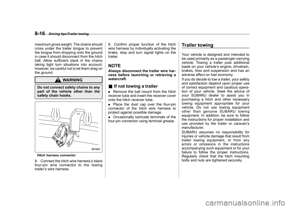
safety chain hooks.Hitch harness connector8. Connect the hitch wire harness’s black
four-pin wire connector to the towing
trailer’s wire harness.9. Confirm proper function of the hitch
wire harness by individually activating the
brake, stop and turn signal lights on the
trailer.
NOTEAlways disconnect the trailer wire har-
ness before launching or retrieving a
watercraft.&If not towing a trailer.Remove the ball mount from the hitch
receiver tube and insert the receiver cover
onto the hitch receiver tube.
.Place the dust cap over the four-pin
connector of the hitch wire harness to
protect against possible damage.
.Occasionally lubricate terminals of the
four-pin connector using terminal grease.
Trailer towingYour vehicle is designed and intended to
be used primarily as a passenger-carrying
vehicle. Towing a trailer puts additional
loads on your vehicle’s engine, drivetrain,
brakes, tires and suspension and has an
adverse effect on fuel economy.
If you do decide to tow a trailer, your safety
and satisfaction depend upon proper use
of correct equipment and cautious opera-
tion of your vehicle. Seek the advice of
your SUBARU dealer to assist you in
purchasing a hitch and other necessary
towing equipment appropriate for your
vehicle. Do not use towing equipment
other than genuine SUBARU towing
equipment. In addition, be sure to follow
the instructions for proper installation and
use provided by the trailer or caravan’s
manufacturer.
SUBARU assumes no responsibility for
injuries or vehicle damage that result from
trailer towing equipment, or from any
errors or omissions in the instructions
accompanying such equipment or for your
failure to follow the proper instructions.
Regularly check that the hitch mounting
bolts and nuts are tightened securely.
Driving tips/Trailer towing
8-16