Page 43 of 180
41
With the automatic air
conditioning system
F Press the dedicated button, its indicator lamp comes on.
F
T
o switch it off, press this button again; its
indicator lamp goes off.
The other settings (air flow, air distribution,
etc.) are controlled automatically.
Rear screen demist –
defrost
The control button is located
on the heating/ventilation or air
conditioning system control panel.
Switching on
The rear screen demist – defrost can only
operate when the engine is running.
F
P
ress this button to demist /defrost the rear
screen and, depending on version, the door
mirrors. The indicator lamp associated with
the button comes on.
Switching off
F Press this button again to switch off the demisting/defrosting. The indicator lamp
associated with the button goes off.
Switch off the demisting/defrosting of
the rear screen and door mirrors, if
fitted, as soon as appropriate, as lower
current consumption results in reduced
fuel consumption.
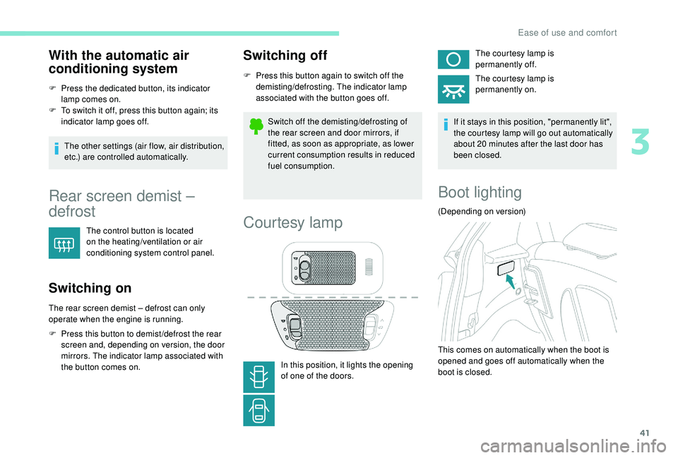
Courtesy lamp
In this position, it lights the opening
of one of the doors. The courtesy lamp is
permanently off.
The courtesy lamp is
permanently on.
If it stays in this position, "permanently lit",
the courtesy lamp will go out automatically
about 20 minutes after the last door has
been closed.
Boot lighting
(Depending on version)
This comes on automatically when the boot is
opened and goes off automatically when the
boot is closed.
3
Ease of use and comfort
Page 46 of 180
44
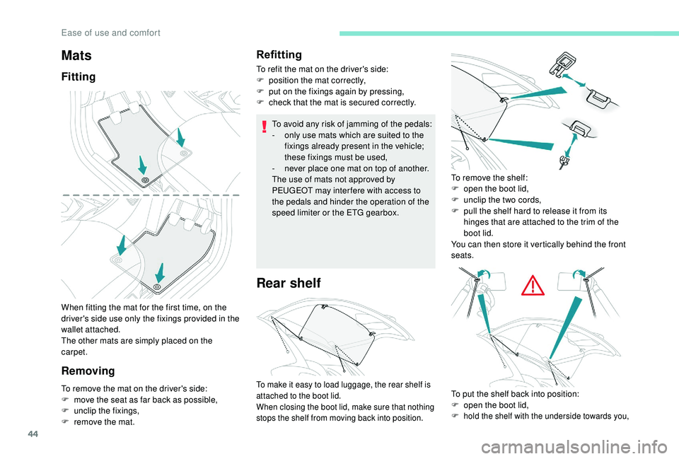
When fitting the mat for the first time, on the
driver's side use only the fixings provided in the
wallet attached.
The other mats are simply placed on the
carpet.
RemovingRefitting
To refit the mat on the driver's side:
F
p osition the mat correctly,
F
p
ut on the fixings again by pressing,
F
c
heck that the mat is secured correctly.
To avoid any risk of jamming of the pedals:
-
o
nly use mats which are suited to the
fixings already present in the vehicle;
these fixings must be used,
-
n
ever place one mat on top of another.
The use of mats not approved by
PEUGEOT may inter fere with access to
the pedals and hinder the operation of the
speed limiter or the ETG gearbox.
Rear shelf
Mats
Fitting
To remove the mat on the driver's side:
F
m ove the seat as far back as possible,
F
un
clip the fixings,
F
r
emove the mat. To remove the shelf:
F
o
pen the boot lid,
F
u
nclip the two cords,
F
p
ull the shelf hard to release it from its
hinges that are attached to the trim of the
boot lid.
You can then store it vertically behind the front
seats.To make it easy to load luggage, the rear shelf is
attached to the boot lid.
When closing the boot lid, make sure that nothing
stops the shelf from moving back into position.To put the shelf back into position:
F o pen the boot lid,
F
hold the shelf with the underside towards you,
Ease of use and comfort
Page 47 of 180
45
Do not place heavy objects on the shelf,
this may cause it to become unclipped.
Boot fittings
1.Hooks.
2. Temporary use spare wheel and tools or
under floor storage.
Be absolutely certain to put the temporary
use spare wheel or the under floor storage
back in place before loading the boot.
Hooks
Maximum weight permitted on the hooks:
2
kg .
Storage box
Depending on configuration, it includes
dedicated storage fittings for:
-
t
owing eye,
-
t
emporary puncture repair kit.
For the versions with a
storage box: it
must be put back in place before loading
the boot.
F
c
lip the shelf into both hinges,
F
p
ass the two cords through the guide hooks
on each side of the struts,
F
c
lip both cords into place.
These can be used to secure shopping bags.
F
P
ull back the boot carpet to access the
storage box.
3
Ease of use and comfort
Page 106 of 180
104
Temporary puncture
repair kit
Scan the QR code on page 3 to view
e xplanatory videos.
Comprising a
compressor and a sealant
cartridge, it allows the temporary repair of
a
tyre so that you can drive to the nearest
garage.
It is designed to repair most punctures which
could affect the tyre, located on the tyre tread
or shoulder.
Access to the kit
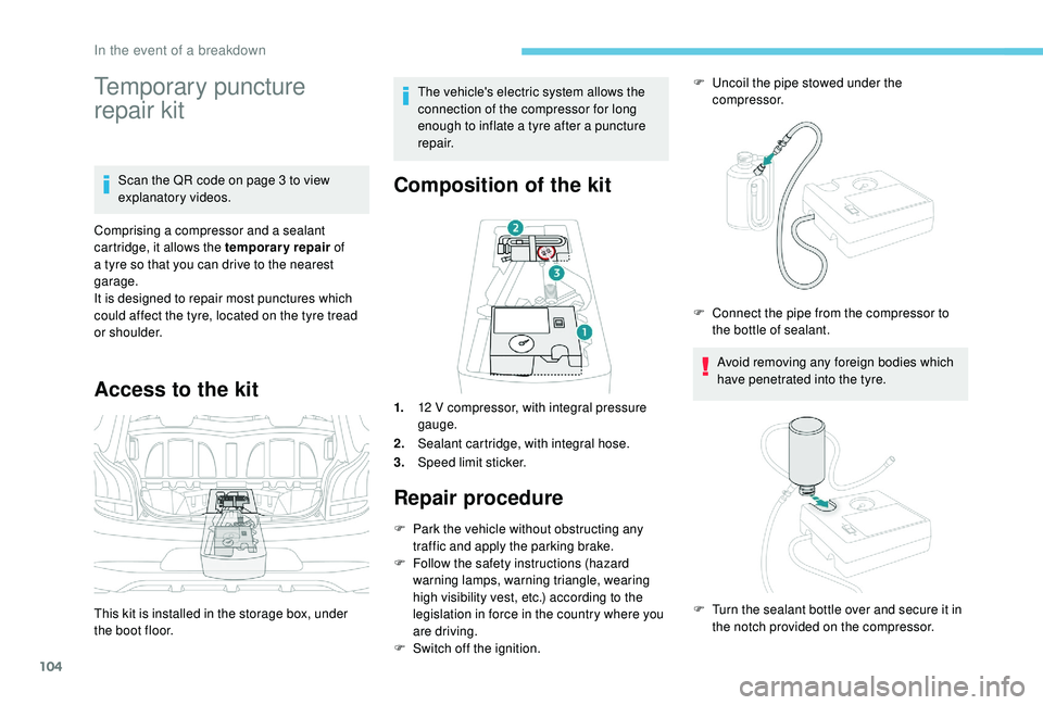
This kit is installed in the storage box, under
the boot floor. The vehicle's electric system allows the
connection of the compressor for long
enough to inflate a
tyre after a puncture
repair.
Composition of the kit
1. 12 V compressor, with integral pressure
gauge.
2. Sealant cartridge, with integral hose.
3. Speed limit sticker.
Repair procedure
F Park the vehicle without obstructing any
traffic and apply the parking brake.
F
F
ollow the safety instructions (hazard
warning lamps, warning triangle, wearing
high visibility vest, etc.) according to the
legislation in force in the country where you
are driving.
F
S
witch off the ignition. F
U
ncoil the pipe stowed under the
compressor.
Avoid removing any foreign bodies which
have penetrated into the tyre.
F
C
onnect the pipe from the compressor to
the bottle of sealant.
F
T
urn the sealant bottle over and secure it in
the notch provided on the compressor.
In the event of a breakdown
Page 109 of 180
107
If a pressure of 2 bars is not reached after
7 minutes, this indicates that the tyre is not
repairable; contact a
PEUGEOT dealer or
a
qualified workshop for assistance.
F
O
nce the correct pressure is reached, put
the switch to the " O" position.
F
R
emove the kit then stow it. Do not drive more than 120
mph
(200 km/h) with the repaired tyre; see
a PEUGEOT dealer or a qualified
workshop to change the tyre.
Tyre under-inflation detection After a tyre repair, the warning
lamp will remain on until the
system is reset.
For more information on Tyre under-
inflation detection , refer to the
corresponding section.
Should the pressure of one or more tyres
be adjusted, it is necessary to reinitialise
the under-inflation detection system.
For more information on Tyre under-
inflation detection , refer to the
corresponding section.
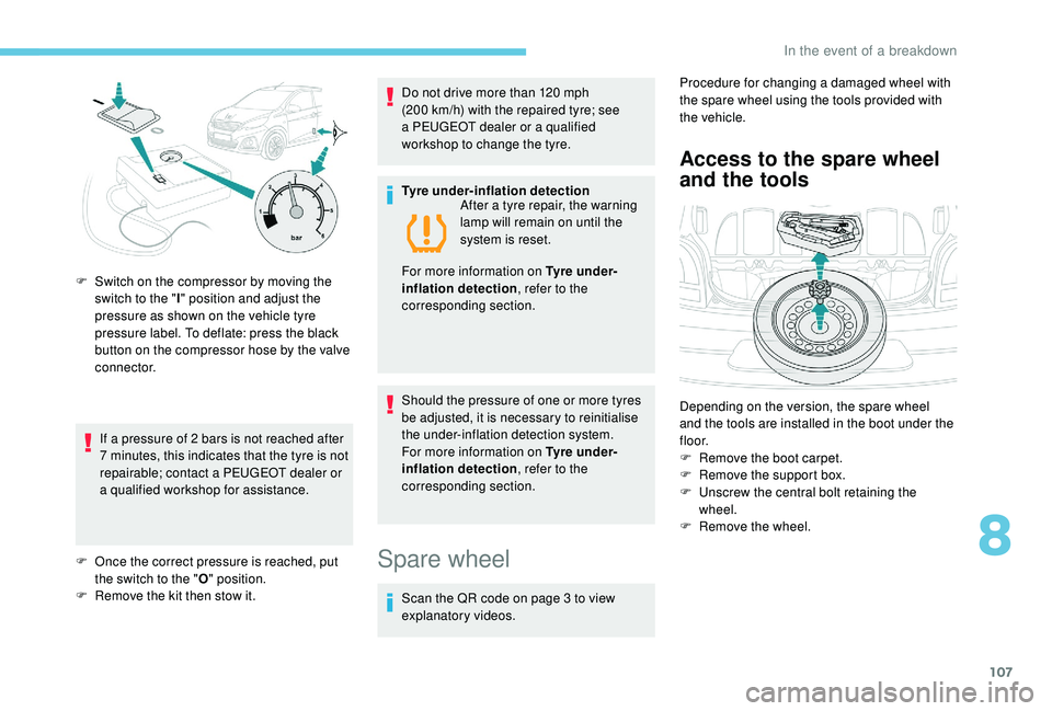
F
S
witch on the compressor by moving the
switch to the " I" position and adjust the
pressure as shown on the vehicle tyre
pressure label. To deflate: press the black
button on the compressor hose by the valve
connector.
Spare wheel
Scan the QR code on page 3 to view
e xplanatory videos. Procedure for changing a
damaged wheel with
the spare wheel using the tools provided with
the vehicle.
Access to the spare wheel
and the tools
Depending on the version, the spare wheel
and the tools are installed in the boot under the
f l o o r.
F
R
emove the boot carpet.
F
R
emove the support box.
F
U
nscrew the central bolt retaining the
wheel.
F
R
emove the wheel.
8
In the event of a breakdown
Page 112 of 180
110
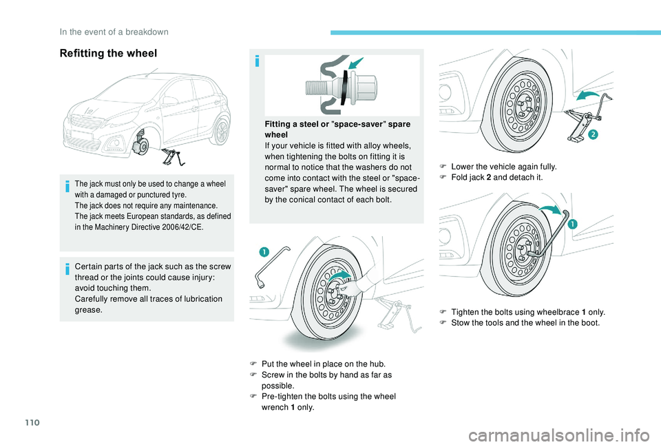
Refitting the wheel
The jack must only be used to change a wheel
w ith a damaged or punctured tyre.
The jack does not require any maintenance.
The jack meets European standards, as defined
in the Machinery Directive 2006/42/CE.
Certain parts of the jack such as the screw
thread or the joints could cause injury:
avoid touching them.
Carefully remove all traces of lubrication
grease.
F
P
ut the wheel in place on the hub.
F
S
crew in the bolts by hand as far as
possible.
F
P
re-tighten the bolts using the wheel
wrench 1
o n l y.F
L
ower the vehicle again fully.
F
F
old jack 2 and detach it.
F
T
ighten the bolts using wheelbrace 1 o n l y.
F
S
tow the tools and the wheel in the boot.
Fitting a
steel or "
space-saver " spare
wheel
If your vehicle is fitted with alloy wheels,
when tightening the bolts on fitting it is
normal to notice that the washers do not
come into contact with the steel or "space-
saver" spare wheel. The wheel is secured
by the conical contact of each bolt.
In the event of a breakdown
Page 115 of 180
113
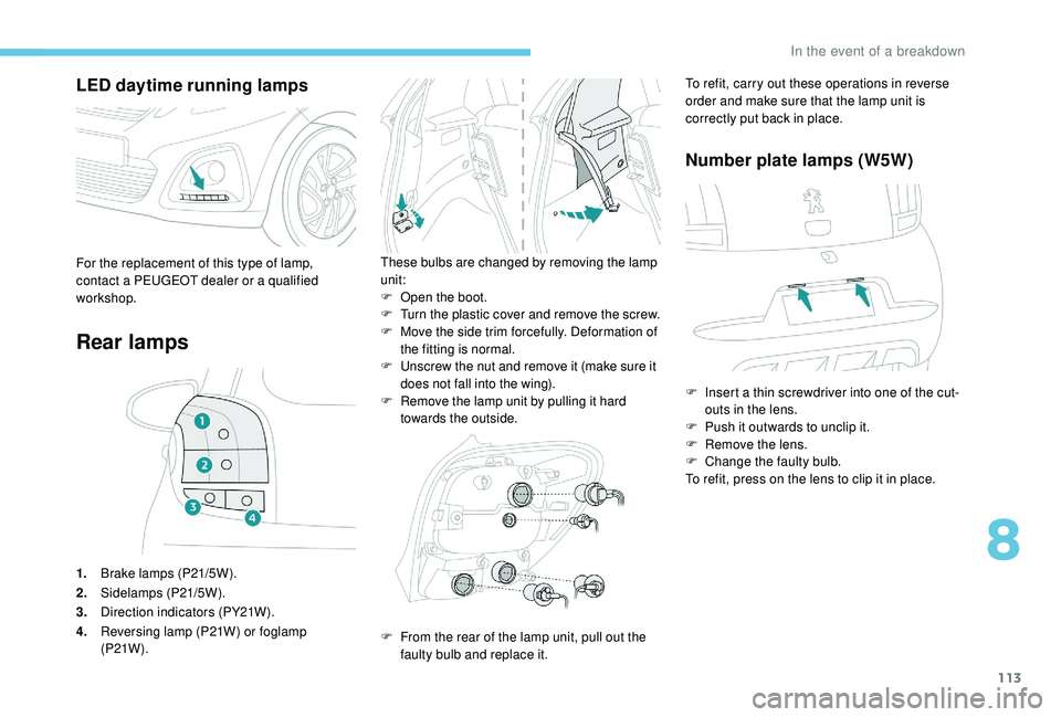
LED daytime running lamps
Rear lamps
1.Brake lamps (P21/5W).
2. Sidelamps (P21/5W).
3. Direction indicators (PY21W).
4. Reversing lamp (P21W) or foglamp
(P21W ).
These bulbs are changed by removing the lamp
unit:
F
O
pen the boot.
F
T
urn the plastic cover and remove the screw.
F
M
ove the side trim forcefully. Deformation of
the fitting is normal.
F
U
nscrew the nut and remove it (make sure it
does not fall into the wing).
F
R
emove the lamp unit by pulling it hard
towards the outside.For the replacement of this type of lamp,
contact a PEUGEOT dealer or a qualified
workshop.
F
F
rom the rear of the lamp unit, pull out the
faulty bulb and replace it. To refit, carry out these operations in reverse
order and make sure that the lamp unit is
correctly put back in place.
Number plate lamps (W5W)
F Insert a
thin screwdriver into one of the cut-
outs in the lens.
F
P
ush it outwards to unclip it.
F
R
emove the lens.
F
C
hange the faulty bulb.
To refit, press on the lens to clip it in place.
8
In the event of a breakdown
Page 116 of 180
114
Third brake lamp (4 W5W bulbs)D irection indicator side repeaters
(WY5W amber)
Changing a fuse
The fuseboxes are located below the
dashboard in the passenger compartment and
beside the battery in the engine compartment.
Access to the tools
The extraction tweezers are attached to the
fusebox under the bonnet. When you unclip the plastic cover, make
sure not to remove the seal.
F
W
ith the boot open, unclip the plastic cover.
F
P
ress on the metal tabs to disengage the
lamp unit.
F
R
emove the lamp unit from outside of the
tailgate.
F
R
emove the bulb holder by squeezing the
two plastic tabs.
F
C
hange the defective bulb(s).
To refit, carry out these operations in reverse
o r d e r. F
P
ush the repeater to the front or to the rear
and disengage it by pulling it towards you.
F
D
isconnect the bulb holder and replace it.
F
U
nclip the plastic cover, located at the
bottom of the windscreen, by pressing on
both tabs.
In the event of a breakdown