Page 118 of 426
Security indicator light
This light blinks when the ignition switch is
placed in the LOCK position with the key
removed from the ignition switch.
This function indicates the NISSAN Vehicle
Immobilizer System is operational.
If the NISSAN Vehicle Immobilizer System is
malfunctioning, the light will remain on
while the ignition switch is placed in the ON
position.If the light still remains on and/or the
engine will not start, seek service for the
NISSAN Vehicle Immobilizer System as
soon as possible. Please bring all regis-
tered keys that you have. It is recom-
mended that you visit a NISSAN dealer
for this service.
SWITCH OPERATION
WARNING
In freezing temperatures the washer
solution may freeze on the windshield
and obscure your vision which may lead
to an accident. Warm the windshield
with the defroster before you wash the
windshield.
CAUTION
∙ Do not operate the washer continu-
ously for more than 30 seconds.
LIC0474LIC3035
WIPER AND WASHER SWITCH
Instruments and controls2-29
Page 119 of 426
∙ Do not operate the washer if thewindshield-washer fluid reservoir is
empty.
∙ Do not fill the windshield-washer fluid reservoir with windshield-washer
fluid concentrates at full strength.
Some methyl alcohol based
windshield-washer fluid concen-
trates may permanently stain the
grille if spilled while filling the
windshield-washer fluid reservoir.
∙ Pre-mix windshield-washer fluid con- centrates with water to the manufac-
turer’s recommended levels before
pouring the fluid into the windshield-
washer fluid reservoir. Do not use the
windshield-washer fluid reservoir to
mix the windshield-washer fluid con-
centrate and water.
The windshield wiper and washer operates
when the ignition switch is in the ON posi-
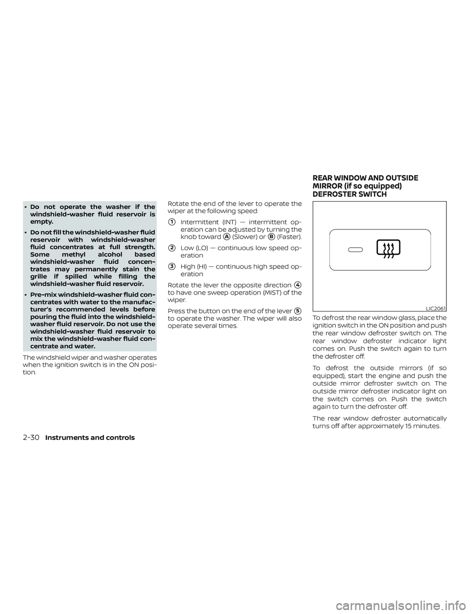
tion. Rotate the end of the lever to operate the
wiper at the following speed:
�1Intermittent (INT) — intermittent op-
eration can be adjusted by turning the
knob toward
�A(Slower) or�B(Faster).
�2Low (LO) — continuous low speed op-
eration
�3High (HI) — continuous high speed op-
eration
Rotate the lever the opposite direction
�4
to have one sweep operation (MIST) of the
wiper.
Press the button on the end of the lever
�5
to operate the washer. The wiper will also
operate several times. To defrost the rear window glass, place the
ignition switch in the ON position and push
the rear window defroster switch on. The
rear window defroster indicator light
comes on. Push the switch again to turn
the defroster off.
To defrost the outside mirrors (if so
equipped), start the engine and push the
outside mirror defroster switch on. The
outside mirror defroster indicator light on
the switch comes on. Push the switch
again to turn the defroster off.
The rear window defroster automatically
turns off af ter approximately 15 minutes.
LIC2061
REAR WINDOW AND OUTSIDE
MIRROR (if so equipped)
DEFROSTER SWITCH
2-30Instruments and controls
Page 121 of 426
Headlight beam select
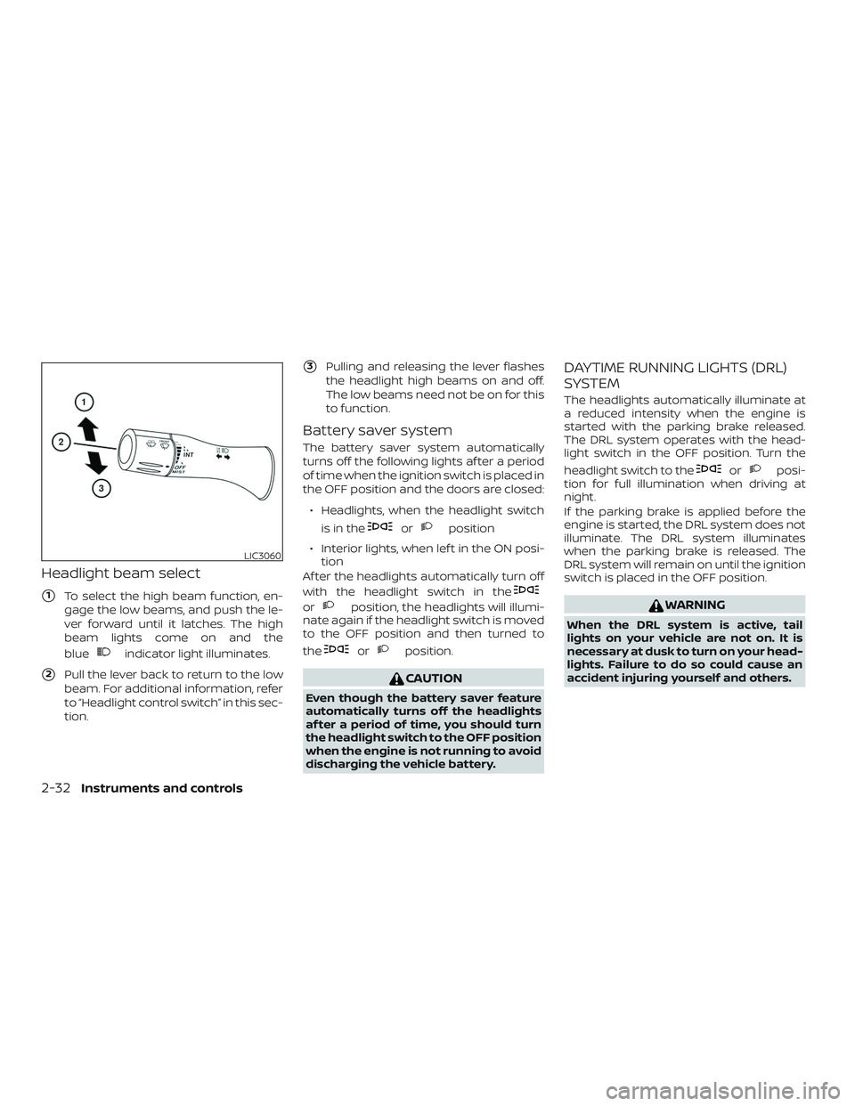
�1To select the high beam function, en-
gage the low beams, and push the le-
ver forward until it latches. The high
beam lights come on and the
blue
indicator light illuminates.
�2Pull the lever back to return to the low
beam. For additional information, refer
to “Headlight control switch” in this sec-
tion.
�3Pulling and releasing the lever flashes
the headlight high beams on and off.
The low beams need not be on for this
to function.
Battery saver system
The battery saver system automatically
turns off the following lights af ter a period
of time when the ignition switch is placed in
the OFF position and the doors are closed:
∙ Headlights, when the headlight switch is in the
orposition
∙ Interior lights, when lef t in the ON posi- tion
Af ter the headlights automatically turn off
with the headlight switch in the
orposition, the headlights will illumi-
nate again if the headlight switch is moved
to the OFF position and then turned to
the
orposition.
CAUTION
Even though the battery saver feature
automatically turns off the headlights
af ter a period of time, you should turn
the headlight switch to the OFF position
when the engine is not running to avoid
discharging the vehicle battery.
DAYTIME RUNNING LIGHTS (DRL)
SYSTEM
The headlights automatically illuminate at
a reduced intensity when the engine is
started with the parking brake released.
The DRL system operates with the head-
light switch in the OFF position. Turn the
headlight switch to the
orposi-
tion for full illumination when driving at
night.
If the parking brake is applied before the
engine is started, the DRL system does not
illuminate. The DRL system illuminates
when the parking brake is released. The
DRL system will remain on until the ignition
switch is placed in the OFF position.
WARNING
When the DRL system is active, tail
lights on your vehicle are not on. It is
necessary at dusk to turn on your head-
lights. Failure to do so could cause an
accident injuring yourself and others.
LIC3060
2-32Instruments and controls
Page 125 of 426
Push the VDC OFF switch again or restart
the engine to turn on the system. For addi-
tional information, refer to “Vehicle Dy-
namic Control (VDC) system” in the “Start-
ing and driving” section of this manual.To use the outlets for devices that require
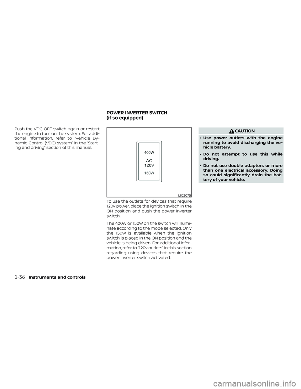
120v power, place the ignition switch in the
ON position and push the power inverter
switch.
The 400W or 150W on the switch will illumi-
nate according to the mode selected. Only
the 150W is available when the ignition
switch is placed in the ON position and the
vehicle is being driven. For additional infor-
mation, refer to “120v outlets” in this section
regarding using devices that require the
power inverter switch activated.CAUTION
∙ Use power outlets with the enginerunning to avoid discharging the ve-
hicle battery.
∙ Do not attempt to use this while driving.
∙ Do not use double adapters or more than one electrical accessory. Doing
so could significantly drain the bat-
tery of your vehicle.
LIC2075
POWER INVERTER SWITCH
(if so equipped)
2-36Instruments and controls
Page 126 of 426
WARNING
The RSS is a convenience but it is not a
substitute for proper backing. Always
turn and check that it is safe to do so
before backing up. Always back up
slowly.
The RSS is active when the ignition switch
is placed to the ON position and the shif t
lever is in R (Reverse).
When sensors detect obstacles within 5.9 f t
(1.8 m) of the rear bumper, a beeping tone is
emitted. The RSS can be disabled by pushing the
OFF switch. When the system is disabled,
the indicator light on the switch will illumi-
nate. Push the switch again to enable the
system. The indicator light will go off.
The system will automatically reset the
next time the ignition switch is placed in
the ON position.
For additional information, refer to “Rear
Sonar System (RSS)” in the “Starting and
driving” section of this manual.
WARNING
∙ The front sonar system is a conve-
nience but it is not a substitute for
proper driving.
∙ The rear sonar system is a conve- nience but it is not a substitute for
proper backing. Always turn and
check that it is safe to do so before
backing up. Always back up slowly.
The front sonar system is active when the
ignition switch is in the ON position and the
shif t lever is in a forward gear position.
LIC2074LIC1182
REAR SONAR SYSTEM (RSS) OFF
SWITCH (if so equipped) FRONT AND REAR SONAR SYSTEM
OFF SWITCH (if so equipped)
Instruments and controls2-37
Page 127 of 426
A beeping tone is emitted when the sen-
sors detect obstacles within 3 f t (1.0 m) of
the front bumper.
The rear sonar system is active when the
ignition switch is in the ON position and the
shif t lever is in R (Reverse). A beeping tone is
emitted when the sensors detect ob-
stacles within 5.9 f t (1.8 m) of the rear bum-
per.
The front and rear sonar system can be
disabled by pushing the OFF switch. When
the system is disabled, the indicator light
on the switch will illuminate. Push the
switch again to enable the system. The in-
dicator light will go off.
The system will automatically reset the
next time the ignition switch is placed in
the ON position.
For additional information, refer to “Front
and rear sonar system” in the “Starting and
driving” section of this manual.Tow mode should be used when pulling a
heavy trailer or hauling a heavy load. Driv-
ing the vehicle in the tow mode with no
trailer/load or light trailer/light load will not
cause any damage. However, fuel
economy may be reduced and the
transmission/engine driving characteris-
tics may feel unusual.
Push the tow mode switch to activate tow
mode. The
TOWindicator will come on
when tow mode is selected. Push the tow
mode switch again to turn the tow mode
off.
Tow mode is automatically canceled when
the key is turned off. For additional information, refer to “Tow
mode” in the “Technical and consumer in-
formation” section of this manual.
LIC2111
TOW MODE SWITCH (if so equipped)
2-38Instruments and controls
Page 128 of 426
12V OUTLET(s)
The power outlets are for powering electri-
cal accessories such as cellular tele-
phones. They are rated at 12 volt, 120W (10A)
maximum.
Open the cap to use a power outlet.The power outlets on the instrument panel
and the 3rd row (if so equipped) are pow-
ered only when the ignition switch is in the
ACC or ON position.
The power outlet inside the console (if so
equipped) is powered directly by the vehi-
cle’s battery.
CAUTION
∙ The outlet and plug may be hot during
or immediately af ter use.
∙ Only certain power outlets are de- signed for use with a cigarette lighter
unit. Do not use any other power out-
let for an accessory lighter. It is rec-
ommended that you visit a NISSAN
dealer for additional information.
12v Instrument Panel
LIC2076
12v 3rd Row (if so equipped)
LIC2199
12v Center console (if so equipped)
LIC2077
POWER OUTLETS
Instruments and controls2-39
Page 134 of 426
Removable center console
To remove the center console:1. Stop the vehicle and place the ignition switch in the OFF position.
2. Lif t out tray.
3. Unplug all accessories from the outlets. 4. Remove the four bolts located inside
the console and two in the front stor-
age tray. 5. Disconnect the power supply. The con-
nector may need to be accessed from
the driver’s door side of the seat by
reaching underneath the seat.
LIC2087LIC2100LIC2102
Instruments and controls2-45