2018 NISSAN NV PASSENGER VAN ignition
[x] Cancel search: ignitionPage 293 of 426
∙ The system is designed as an aid tothe driver in detecting large station-
ary objects to help avoid damaging
the vehicle. The system will not detect
small objects below the bumper, and
may not detect objects close to the
bumper or on the ground.
∙ If your vehicle sustains damage to the rear bumper fascia, leaving it mis-
aligned or bent, the sensing zone may
be altered causing inaccurate mea-
surement of obstacles or false alarms.
The RSS sounds a tone to warn the driver of
obstacles near the rear bumper when the
shif t lever is in R (Reverse). The system may
not detect objects at speeds above 3 mph
(5 km/h) and may not detect certain angu-
lar or moving objects.
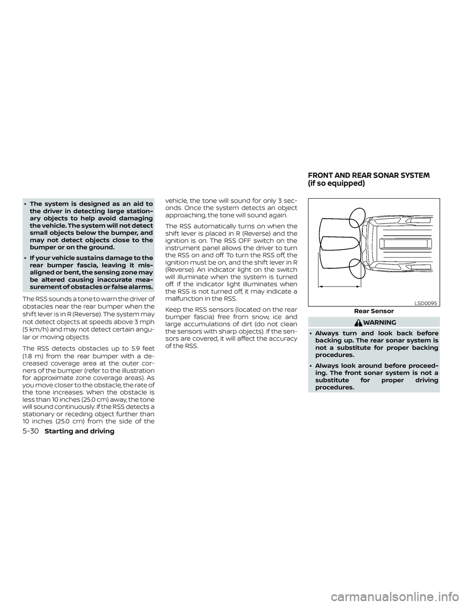
The RSS detects obstacles up to 5.9 feet
(1.8 m) from the rear bumper with a de-
creased coverage area at the outer cor-
ners of the bumper (refer to the illustration
for approximate zone coverage areas). As
you move closer to the obstacle, the rate of
the tone increases. When the obstacle is
less than 10 inches (25.0 cm) away, the tone
will sound continuously. If the RSS detects a
stationary or receding object further than
10 inches (25.0 cm) from the side of the vehicle, the tone will sound for only 3 sec-
onds. Once the system detects an object
approaching, the tone will sound again.
The RSS automatically turns on when the
shif t lever is placed in R (Reverse) and the
ignition is on. The RSS OFF switch on the
instrument panel allows the driver to turn
the RSS on and off. To turn the RSS off, the
ignition must be on, and the shif t lever in R
(Reverse). An indicator light on the switch
will illuminate when the system is turned
off. If the indicator light illuminates when
the RSS is not turned off, it may indicate a
malfunction in the RSS.
Keep the RSS sensors (located on the rear
bumper fascia) free from snow, ice and
large accumulations of dirt (do not clean
the sensors with sharp objects). If the sen-
sors are covered, it will affect the accuracy
of the RSS.
WARNING
∙ Always turn and look back before
backing up. The rear sonar system is
not a substitute for proper backing
procedures.
∙ Always look around before proceed- ing. The front sonar system is not a
substitute for proper driving
procedures.
Rear Sensor
LSD0095
FRONT AND REAR SONAR SYSTEM
(if so equipped)
5-30Starting and driving
Page 294 of 426
∙ Read and understand the limitationsof the front and rear sonar system as
contained in this section. Inclement
weather may affect the function of
the sonar system; this may include re-
duced performance or a false
activation.
∙ This system is not designed to pre- vent contact with small or moving
objects. ∙ The system is designed as an aid to
the driver in detecting large station-
ary objects to help avoid damaging
the vehicle. The system will not detect
small objects below the bumper, and
may not detect objects close to the
bumper or on the ground.
∙ If your vehicle sustains damage to the front bumper fascia or the rear bum-
per fascia, leaving it misaligned or
bent, the sensing zone may be altered
causing inaccurate measurement of
obstacles or false alarms.
The rear sonar system sounds a tone to
warn the driver of obstacles near the rear
bumper. The rear sonar system automati-
cally turns on when the shif t lever is placed
in R (Reverse) and the ignition is ON. The
system may not detect objects at speeds
above 3 mph (5 km/h) and may not detect
certain angular or moving objects.
The rear sonar system detects obstacles
up to 5.9 f t (1.8 m) from the rear bumper
with a decreased coverage area at the
outer corners of the bumper. As you move
closer to the obstacle, the rate of the tone
increases. When the obstacle is less than
10 in (25 cm) away, the tone will sound con-
tinuously. If it detects a stationary or reced- ing object further than 10 in (25 cm) from
the side of the vehicle, the tone will sound
for only 3 seconds. Once the system de-
tects an object approaching, the tone will
sound again.
The front sonar system sounds a tone to
warn the driver of obstacles near the front
bumper. The front sonar system automati-
cally turns on when the shif t lever is placed
in a forward gear and the ignition switch is
in the ON position. The system may not
detect objects at speeds above 3 mph
(5 km/h) and may not detect certain angu-
lar or moving objects.
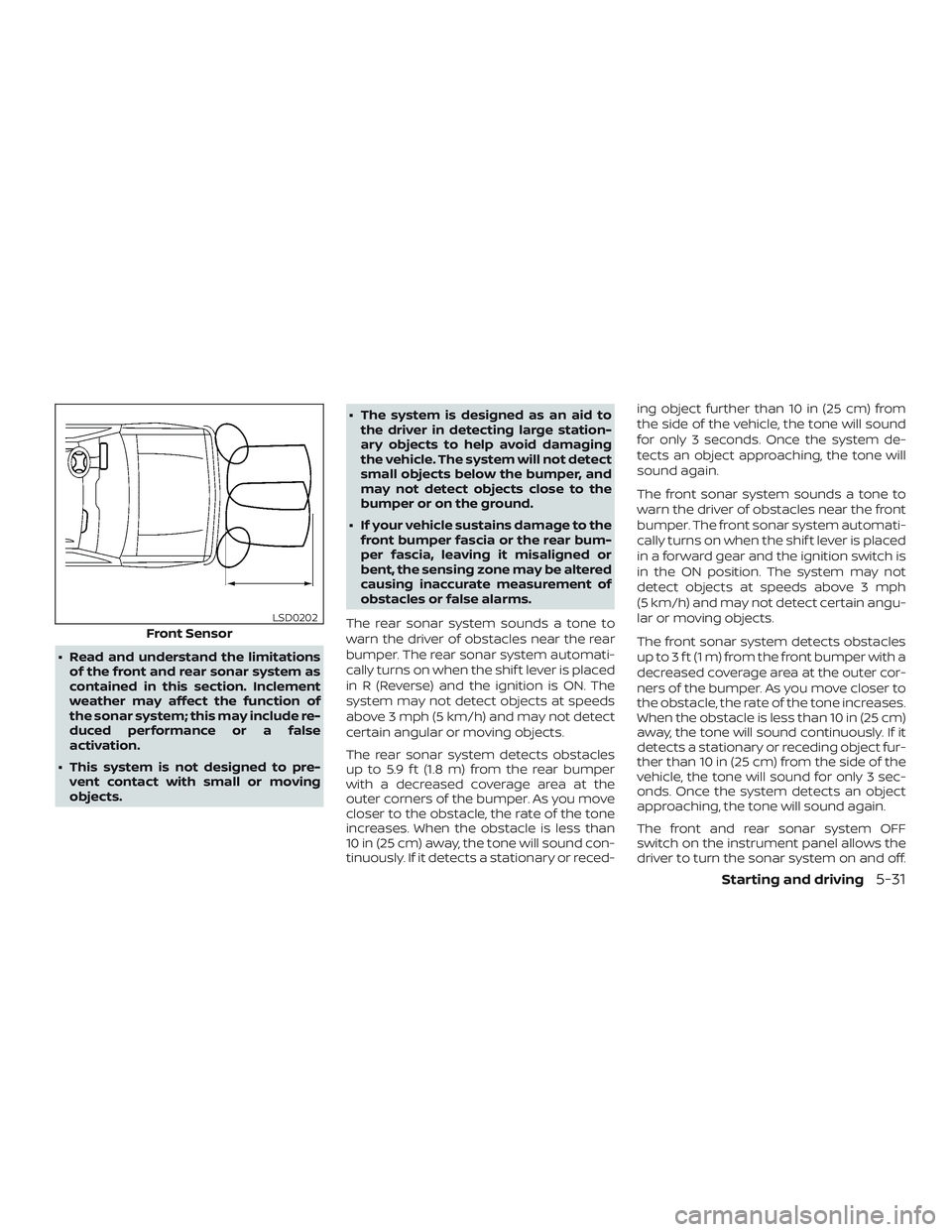
The front sonar system detects obstacles
up to 3 f t (1 m) from the front bumper with a
decreased coverage area at the outer cor-
ners of the bumper. As you move closer to
the obstacle, the rate of the tone increases.
When the obstacle is less than 10 in (25 cm)
away, the tone will sound continuously. If it
detects a stationary or receding object fur-
ther than 10 in (25 cm) from the side of the
vehicle, the tone will sound for only 3 sec-
onds. Once the system detects an object
approaching, the tone will sound again.
The front and rear sonar system OFF
switch on the instrument panel allows the
driver to turn the sonar system on and off.
Front Sensor
LSD0202
Starting and driving5-31
Page 295 of 426
To turn the system off, the ignition must be
ON and the shif t lever in R (Reverse) or D
(Drive). An indicator light on the switch will
illuminate when the system is turned off. If
the indicator light illuminates when the
system is not turned off, it may indicate a
failure in the sonar system.
Keep the front and rear sonar sensors (lo-
cated on the bumper fascia) free from
snow, ice and large accumulations of dirt
(do not clean the sensors with sharp ob-
jects). If the sensors are covered, it will af-
fect the accuracy of the sonar system.FREEING A FROZEN DOOR LOCK
To prevent a door lock from freezing, apply
de-icer through the key hole. If the lock
becomes frozen, heat the key before in-
serting it into the key hole or use the re-
mote keyless entry key fob (if so equipped).
ANTIFREEZE
In the winter when it is anticipated that the
temperature will drop below 32°F (0°C),
check the antifreeze to assure proper win-
ter protection. For additional information,
refer to “Engine cooling system” in the “Do-
it-yourself ” section of this manual.
BATTERY
If the battery is not fully charged during
extremely cold weather conditions, the
battery fluid may freeze and damage the
battery. To maintain maximum efficiency,
the battery should be checked regularly.
For additional information, refer to “Battery”
in the “Do-it-yourself ” section of this
manual.
DRAINING OF COOLANT WATER
If the vehicle is to be lef t outside without
anti-freeze, drain the cooling system, in-
cluding the engine block. Refill before oper-
ating the vehicle. For additional informa-
tion, refer to “Changing engine coolant” in
the “Do-it-yourself ” section of this manual.
TIRE EQUIPMENT
1. SUMMER tires have a tread designed toprovide superior performance on dry
pavement. However, the performance
of these tires will be substantially re-
duced in snowy and icy conditions. If
you operate your vehicle on snowy or
icy roads, NISSAN recommends the use
of MUD & SNOW or ALL SEASON TIRES
on all four wheels. It is recommended
that you visit a NISSAN dealer for the tire
type, size, speed rating and availability
information.
2. For additional traction on icy roads, studded tires may be used. However,
some U.S. states and Canadian prov-
inces prohibit their use. Check local,
state and provincial laws before install-
ing studded tires.
COLD WEATHER DRIVING
5-32Starting and driving
Page 299 of 426
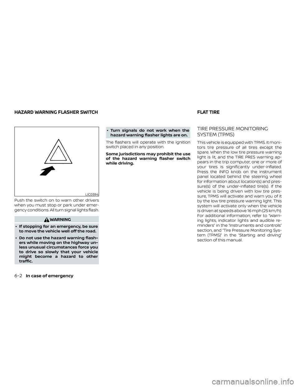
Push the switch on to warn other drivers
when you must stop or park under emer-
gency conditions. All turn signal lights flash.
WARNING
∙ If stopping for an emergency, be sureto move the vehicle well off the road.
∙ Do not use the hazard warning flash- ers while moving on the highway un-
less unusual circumstances force you
to drive so slowly that your vehicle
might become a hazard to other
traffic. ∙ Turn signals do not work when the
hazard warning flasher lights are on.
The flashers will operate with the ignition
switch placed in any position.
Some jurisdictions may prohibit the use
of the hazard warning flasher switch
while driving.
TIRE PRESSURE MONITORING
SYSTEM (TPMS)
This vehicle is equipped with TPMS. It moni-
tors tire pressure of all tires except the
spare. When the low tire pressure warning
light is lit, and the TIRE PRES warning ap-
pears in the trip computer, one or more of
your tires is significantly under-inflated.
Press the INFO knob on the instrument
panel located behind the steering wheel
for information about location(s) and pres-
sure(s) of the under-inflated tire(s). If the
vehicle is being driven with low tire pres-
sure, TPMS will activate and warn you of it
by the low tire pressure warning light. This
system will activate only when the vehicle
is driven at speeds above 16 mph (25 km/h).
For additional information, refer to “Warn-
ing lights, indicator lights and audible re-
minders” in the “Instruments and controls”
section, and “Tire Pressure Monitoring Sys-
tem (TPMS)” in the “Starting and driving”
section of this manual.
LIC0394
HAZARD WARNING FLASHER SWITCH FLAT TIRE
6-2In case of emergency
Page 312 of 426
CAUTION
∙ Never tow automatic transmissionmodels with the rear wheels on the
ground or four wheels on the ground
(forward or backward), as this may
cause serious and expensive damage
to the transmission. If it is necessary
to tow the vehicle with the front
wheels raised always use towing dol-
lies under the rear wheels.
∙ When towing automatic transmission models with the front wheels on the
ground or on towing dollies:
– Place the ignition switch in the OFF position, and secure the steering
wheel in a straight-ahead position
with a rope or similar device. Never
secure the steering wheel by plac-
ing the ignition switch in the LOCK
position. This may damage the
steering lock mechanism (for
models with a steering lock
mechanism).
VEHICLE RECOVERY
(freeing a stuck vehicle)
There are two options to recover a stuck
vehicle: pulling and rocking. For additional
information regarding these options,
please refer to the following sections.
Pulling a stuck vehicle
WARNING
To avoid vehicle damage, serious per-
sonal injury or death when recovering a
stuck vehicle:
∙ Contact a professional towing serviceto recover the vehicle if you have any
questions regarding the recovery
procedure.
∙ Attach recovery devices only to main structural members of the vehicle or
the recovery hooks.
∙ Do not use the vehicle tie-downs to tow or free a stuck vehicle.
∙ Only use devices specifically designed for vehicle recovery and follow the
manufacturer’s instructions. ∙ Always pull the recovery device
straight out from the front of the ve-
hicle. Never pull at an angle.
∙ Route recovery devices so they do not touch any part of the vehicle except
the attachment point.
If your vehicle is stuck in sand, snow, mud,
etc., use a tow strap or other device de-
signed specifically for vehicle recovery. Al-
ways follow the manufacturer’s instruc-
tions for the recovery device.
Rocking a stuck vehicle
WARNING
∙ Stand clear of a stuck vehicle.
∙ Do not spin your tires at high speed. This could cause them to explode and
result in serious injury. Parts of your
vehicle could also overheat and be
damaged.
If your vehicle is stuck in sand, snow, mud,
etc., use the following procedure: 1. Turn off the Vehicle Dynamic Control (VDC) system .
2. Make sure the area in front and behind the vehicle is clear of obstructions.
In case of emergency6-15
Page 318 of 426
∙ Properly position the mats in thefloorwell using the floor mat position-
ing hook. For additional information,
refer to "Floor mat installation" in this
section.
∙ Make sure the floor mat does not in- terfere with pedal operation.
∙ Periodically check the floor mats to make sure they are properly installed.
∙ Af ter cleaning the vehicle interior, check the floor mats to make sure
they are properly installed.
The use of Genuine NISSAN floor mats can
extend the life of your vehicle carpet and
make it easier to clean the interior. Mats
should be maintained with regular clean-
ing and replaced if they become exces-
sively worn.
Floor mat installation
Your vehicle is equipped with floor mat po-
sitioning hook(s). The number and shape of
the floor mat positioning hooks for each
seating position varies depending on the
vehicle. When installing Genuine NISSAN floor mats,
follow the installation instructions provided
with the mat and the following:
1. With the ignition in the OFF position, the shif t lever in P (Park) position and with
the parking brake fully applied, position
the floor mat in the floorwell so that the
floor mat grommet holes are aligned
with the hook(s).
2. Secure the grommet holes into the hook(s) and ensure that the floor mat is
properly positioned.
3. Make sure the floor mat does not inter- fere with pedal operation. With the igni-
tion still in the OFF position, the shif t
lever in the P (Park) position and with
the parking brake applied, fully apply
and release all pedals. The floor mat
must not interfere with pedal opera-
tion or prevent the pedal from return-
ing to its normal position.
It is recommended that you visit a NISSAN
dealer for details about installing the floor
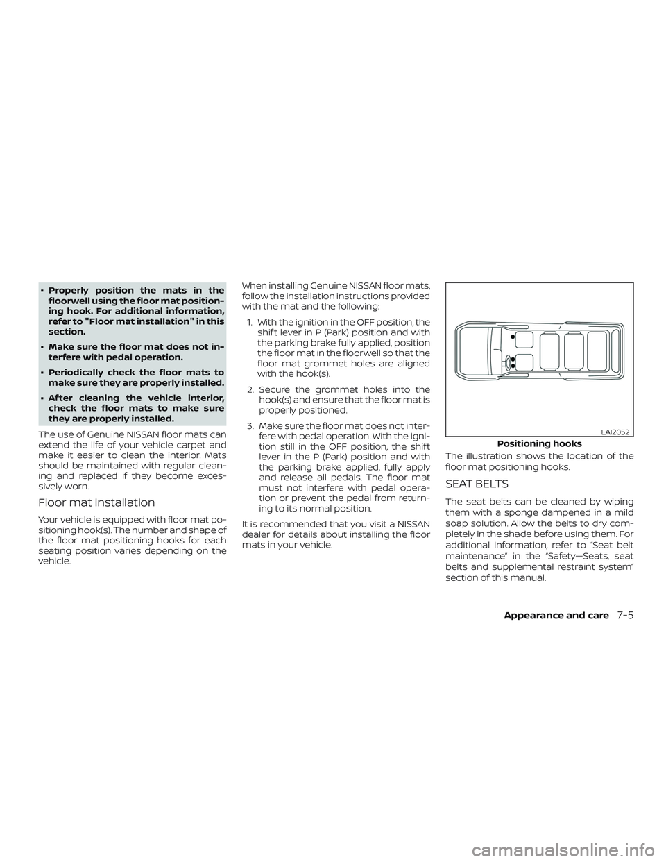
mats in your vehicle. The illustration shows the location of the
floor mat positioning hooks.
SEAT BELTS
The seat belts can be cleaned by wiping
them with a sponge dampened in a mild
soap solution. Allow the belts to dry com-
pletely in the shade before using them. For
additional information, refer to “Seat belt
maintenance” in the “Safety—Seats, seat
belts and supplemental restraint system”
section of this manual.
Positioning hooks
LAI2052
Appearance and care7-5
Page 323 of 426
When performing any inspection or main-
tenance work on your vehicle, always take
care to prevent serious accidental injury to
yourself or damage to the vehicle. The fol-
lowing are general precautions which
should be closely observed.
WARNING
∙ Park the vehicle on a level surface, ap-ply the parking brake securely and
block the wheels to prevent the ve-
hicle from moving. Move the shif t le-
ver to P (Park).
∙ Be sure the ignition key is in the OFF or LOCK position when performing any
parts replacement or repairs.
∙ If you must work with the engine run- ning, keep your hands, clothing, hair
and tools away from moving fans,
belts and any other moving parts.
∙ It is advisable to secure or remove any loose clothing and remove any jew-
elry, such as rings, watches, etc. be-
fore working on your vehicle.
∙ Always wear eye protection whenever you work on your vehicle. ∙ Your vehicle is equipped with an auto-
matic engine cooling fan. It may come
on at any time without warning, even
if the ignition key is in the OFF position
and the engine is not running. To
avoid injury, always disconnect the
negative battery cable before work-
ing near the fan.
∙ If you must run the engine in an en- closed space such as a garage, be sure
there is proper ventilation for exhaust
gases to escape.
∙ Never get under the vehicle while it is supported only by a jack. If it is neces-
sary to work under the vehicle, sup-
port it with safety stands.
∙ Keep smoking materials, flame and sparks away from the fuel tank and
battery.
∙ On gasoline engine models, the fuel filter or fuel lines should be serviced. It
is recommended that you visit a
NISSAN dealer for this service because
the fuel lines are under high pressure
even when the engine is off.
CAUTION
∙ Do not work under the hood while theengine is hot. Turn the engine off and
wait until it cools down.
∙ Avoid contact with used engine oil and coolant. Improperly disposed en-
gine oil, engine coolant and/or other
vehicle fluids can damage the envi-
ronment. Always conform to local
regulations for disposal of vehicle
fluid.
∙ Never leave the engine or the trans- mission related component harness
connector disconnected while the ig-
nition switch is in the ON position.
∙ Never connect or disconnect the bat- tery or any transistorized component
while the ignition switch is in the ON
position.
∙ DO NOT power wash any interior por- tion of this vehicle to help minimize
liquid intrusion and potential elec-
tronic component damage.
This “Do-it-yourself ” section gives instruc-
tions regarding only those items which are
relatively easy for an owner to perform.
MAINTENANCE PRECAUTIONS
8-2Do-it-yourself
Page 338 of 426
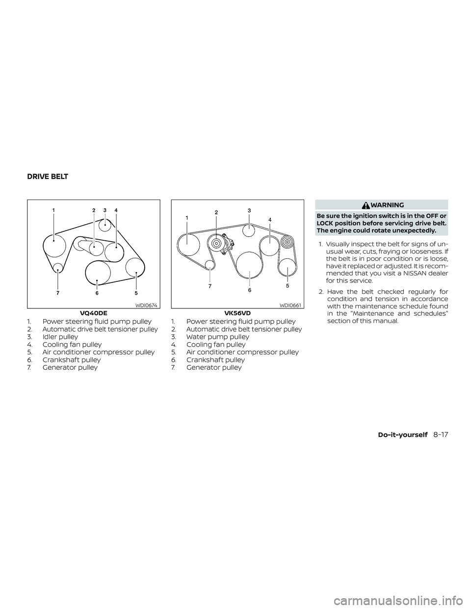
1. Power steering fluid pump pulley
2.Automatic drive belt tensioner pulley3. Idler pulley
4. Cooling fan pulley
5. Air conditioner compressor pulley
6. Crankshaf t pulley
7. Generator pulley1. Power steering fluid pump pulley
2.Automatic drive belt tensioner pulley3. Water pump pulley
4. Cooling fan pulley
5. Air conditioner compressor pulley
6. Crankshaf t pulley
7. Generator pulley
WARNING
Be sure the ignition switch is in the OFF or
LOCK position before servicing drive belt.
The engine could rotate unexpectedly.
1. Visually inspect the belt for signs of un-
usual wear, cuts, fraying or looseness. If
the belt is in poor condition or is loose,
have it replaced or adjusted. It is recom-
mended that you visit a NISSAN dealer
for this service.
2. Have the belt checked regularly for condition and tension in accordance
with the maintenance schedule found
in the "Maintenance and schedules"
section of this manual.
VQ40DE
WDI0674
VK56VD
WDI0661
DRIVE BELT
Do-it-yourself8-17