Page 339 of 426
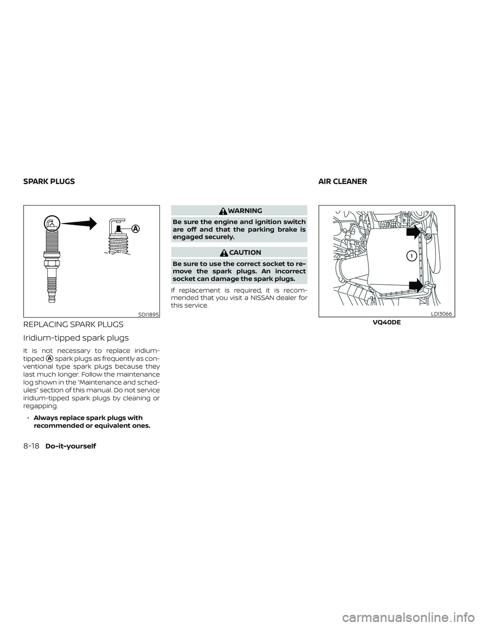
REPLACING SPARK PLUGS
Iridium-tipped spark plugs
It is not necessary to replace iridium-
tipped
�Aspark plugs as frequently as con-
ventional type spark plugs because they
last much longer. Follow the maintenance
log shown in the “Maintenance and sched-
ules” section of this manual. Do not service
iridium-tipped spark plugs by cleaning or
regapping.
∙ Always replace spark plugs with
recommended or equivalent ones.
WARNING
Be sure the engine and ignition switch
are off and that the parking brake is
engaged securely.
CAUTION
Be sure to use the correct socket to re-
move the spark plugs. An incorrect
socket can damage the spark plugs.
If replacement is required, it is recom-
mended that you visit a NISSAN dealer for
this service.
SDI1895
VQ40DE
LDI3066
SPARK PLUGS AIR CLEANER
8-18Do-it-yourself
Page 344 of 426
ENGINE COMPARTMENT
WARNING
Never use a fuse of higher or lower am-
perage rating than that specified on the
fuse box cover. This could damage the
electrical system or electronic control
units or cause a fire.
If any electrical equipment does not come
on, check for an open fuse. 1. Be sure the ignition switch and the headlight switch are OFF. 2. Open the engine hood.
3. Remove the fuse box cover by pushing
the tab and lif ting the cover up.
4. Remove the fuse with the fuse puller. The fuse puller is located in the center
of the fuse block in the passenger
compartment. 5. If the fuse is open
�A, replace it with a
new fuse
�B.
6. If a new fuse also opens, have the elec- trical system checked and repaired. It is
recommended that you visit a NISSAN
dealer for this service.
VQ40DE engine
LDI2825
VK56VD engine
LDI3058LDI2826
Do-it-yourself8-23
Page 345 of 426
Fusible links
If the electrical equipment does not oper-
ate and fuses are in good condition, check
the fusible links. If any of these fusible links
are melted, replace with only Genuine
NISSAN parts.
PASSENGER COMPARTMENT
WARNING
Never use a fuse of higher or lower am-
perage rating than that specified on the
fuse box cover. This could damage the
electrical system or electronic control
units or cause a fire.
If any electrical equipment does not oper-
ate, check for an open fuse. 1.
Be sure the ignition switch and the head-
light switch are in the OFF position.
2. Pull the fuse box cover to remove.
LDI0456LDI2828
8-24Do-it-yourself
Page 347 of 426
How to replace the extended storage
switch:1. To remove the extended storage switch, be sure the ignition switch is in
the OFF or LOCK position.
2. Be sure the headlight switch is in the OFF position.
3. Remove the fuse box cover.
4. Pinch the locking tabs
�Afound on
each side of the storage switch.
5. Pull the storage switch straight out from the fuse box
�B.
CAUTION
Be careful not to allow children to swal-
low the battery or removed parts.
BATTERY REPLACEMENT
8-26Do-it-yourself
Page 363 of 426

If the relearn procedure does not work,
check the following and retry the pro-
cess:∙ If the relearn procedure is stopped be- fore completion, the new tire positions
are not learned. Redo the complete re-
learn procedure to reset the tire posi-
tions.
∙ You must select “RESET TPMS →RE-
LEARN” from the “SETTINGS” menu to
complete the relearn procedure. Redo
the complete relearn procedure to re-
set the tire positions. Select the TPMS
resetting menu, then continue the re-
maining registration procedure.
∙ Adjust the tire pressures to the relearn pressures before selecting the TPMS re-
setting menu on the display. Redo the
complete relearn procedure to reset
the tire positions.
∙ If the tire pressure cannot be reduced at least 10 psi (69 kPa) to adjust them to
the relearn pressures, inflate the tires to
at least 10 psi (69 kPa) above the speci-
fied pressures. Redo the complete re-
learn procedure starting with step 1. ∙ Devices which emit electronic interfer-
ence should be turned off before start-
ing the relearn procedure. The interfer-
ence may prevent the system from
learning the new tire positions. Turn off
or remove sources of electrical interfer-
ence. If necessary, move the vehicle to
another location, then redo the com-
plete relearn procedure to reset the tire
positions.
∙ If you have retried the procedure sev- eral times and the relearn procedure is
not successfully completed, It is recom-
mended that you visit a NISSAN dealer
for this service.
∙ Use an air pump that is capable of in- flating the tires to the required pressure
specifications. The air pump must be
capable of inflating a tire at least 10 psi
(69 kPa) in 30 seconds.
∙ If the reset TPMS function is uninten- tionally selected, place the ignition
switch in the OFF position then to the
ON position to end the relearn proce-
dure. ∙ If the vehicle is not recognizing the new
tire pressure levels, move the vehicle
forward 40 in (1 m). Place the ignition
switch in the OFF position then to the
ON position. Redo the relearn proce-
dure beginning at step 1. Make sure that
the tire pressures are increased or de-
creased at least 10 psi (69 kPa).
∙ When vehicle is in the relearn mode, the TPMS will not warn of low tire pressures
or detect malfunctions.
∙ If tire pressure is not set to the correct pressure, restart the procedure again.
8-42Do-it-yourself
Page 387 of 426
. Do not use E-85 in your ve-
hicle. U.S. government regulations require
fuel ethanol dispensing pumps to be iden-
tified by a small, square, oran")
E-85 can only be used in a Flexible Fuel
Vehicle (FFV). Do not use E-85 in your ve-
hicle. U.S. government regulations require
fuel ethanol dispensing pumps to be iden-
tified by a small, square, orange and black
label with the common abbreviation or the
appropriate percentage for that region.
Fuel containing MMT
MMT, or methylcyclopentadienyl manga-
nese tricarbonyl, is an octane boosting ad-
ditive. NISSAN does not recommend the
use of fuel containing MMT. Such fuel may
adversely affect vehicle performance, in-
cluding the emissions control system. Note
that while some fuel pumps label MMT
content, not all do, so you may have to
consult your gasoline retailer for more de-
tails.
Af termarket fuel additives
NISSAN does not recommend the use of
any af termarket fuel additives (for ex-
ample, fuel injector cleaner, octane
booster, intake valve deposit removers,
etc.) which are sold commercially. Many of
these additives intended for gum, varnish
or deposit removal may contain active sol-
vents or similar ingredients that can be
harmful to the fuel system and engine.
Octane rating tips
Using unleaded gasoline with an octane
rating lower than recommended can
cause persistent, heavy “spark knock.”
(“Spark knock” is a metallic rapping
noise.) If severe, this can lead to engine
damage. If you detect a persistent heavy
spark knock even when using gasoline
of the stated octane rating, or if you hear
steady spark knock while holding a
steady speed on level roads, it is recom-
mended that you have a NISSAN dealer
correct the condition. Failure to correct
the condition is misuse of the vehicle, for
which NISSAN is not responsible.
Incorrect ignition timing may result in
spark knock, af ter-run and/or overheating,
which may cause excessive fuel consump-
tion or engine damage. If any of the above
symptoms are encountered, have your ve-
hicle checked. It is recommended that you
visit a NISSAN dealer for servicing.
However, now and then you may notice
light spark knock for a short time while
accelerating or driving up hills. This is not
a cause for concern, because you get the
greatest fuel benefit when there is light
spark knock for a short time under heavy
engine load.
10-6Technical and consumer information
Page 390 of 426
ENGINE
ModelVQ40DEVK56VD
Type Gasoline, 4-cycle, DOHC Gasoline, 4-cycle, DOHC
Cylinder arrangement 6-cylinder, V-block, Slanted at 60° 8-cylinder, V-block, Slanted at 90°
Bore x Stroke in (mm) 3.76 x 3.622 (95.5 x 92) in (mm) 3.858 x 3.622 (98 x 92)
Displacement cu in (cm
3) 241.3 (3,954)cu in (cm3) 338.8 (5,553)
Firing order 1–2–3–4–5–61–8–7–3–6–5–4–2
Idle speed
No adjustment is necessary. No adjustment is necessary.
A/T (in “N” position)
Ignition timing (degree B.T.D.C. at idle
speed)
CO%atidle
Spark plug
DILFR5A-11 DIKAR7B11
Spark plug gap (Nominal) in (mm) 0.043 (1.1) in (mm) 0.043 (1.1)
Camshaf t operation Timing chain Timing chain
This spark ignition system complies with the Canadian standard ICES-002.
SPECIFICATIONS
Technical and consumer information10-9
Page 405 of 426
.
To install a trailer hitch bal")
Bumper towing
The Genuine NISSAN step bumper has pro-
visions to install a trailer hitch ball and is
designed to tow trailers of a maximum
weight of 2,000 lbs. (907 kg).
To install a trailer hitch ball cut out the circle
in the center of the step bumper
�A, then
remove it to install the trailer hitch ball.
Weight carrying hitches
A weight carrying or “dead weight” ball
mount is one that is designed to carry the
whole amount of tongue weight and gross
weight directly on the ball mount and on
the receiver.
Weight distribution hitch
This type of hitch is also called a “load-
leveling” or “equalizing” hitch. A set of bars
attach to the ball mount and to the trailer
to distribute the tongue weight (hitch
weight) of your trailer. Many vehicles can’t
carry the full tongue weight of a given
trailer, and need some of the tongue
weight transferred through the frame and
pushing down on the front wheels. This
gives stability to the tow vehicle.
A weight-distributing hitch system (Class
IV) is recommended if you plan to tow trail-
ers with a maximum weight over 5,000 lbs.
(2,268 kg). Check with the trailer and towing
equipment manufacturers to determine if
they recommend the use of a weight-
distributing hitch system. NOTE:
A weight-distributing hitch system may
affect the operation of trailer surge
brakes. If you are considering use of a
weight-distributing hitch system with a
surge brake-equipped trailer, check with
the surge brake, hitch or trailer manufac-
turer to determine if and how this can be
done.
Follow the instructions provided by the
manufacturer for installing and using the
weight-distributing hitch system.
General set-up instructions are as follows:
1. Park unloaded vehicle on a level sur- face. With the ignition on and the doors
closed, allow the vehicle to stand for
several minutes so that it can level.
2. Measure the height of a reference point on the front and rear bumpers at the
center of the vehicle.
3. Attach the trailer to the vehicle and ad- just the hitch equalizers so that the
front bumper height is within 0 -
.5 inches (0 – 13 mm) of the reference
height measured in step 2. The rear
bumper should be no higher than the
reference height measured in step 2.
LTI2007
10-24Technical and consumer information


 3.76")