2018 MERCEDES-BENZ SLC ROADSTER wheel
[x] Cancel search: wheelPage 284 of 298
must be positioned vertically, directly under
the jacking point of the vehicle.
!Only position the jack at the appropriate
jacking point of the vehicle. Otherwise, you
could damage the vehicle.
Observe the following when raising the vehicle:
RTo rais ethe vehicle, only use the vehicle-spe-
cific jack that has been tested and approved
by Mercedes-Benz. If used incorrectly, the
jack could tip over with the vehicler aised.
RThe jack is designed only to raiseand hold the
vehiclef oras hort time while awheelisb eing
changed. It must not be used for performing
maintenance work under the vehicle.
RAvoid changing the wheelonu phill and down-
hill slopes.
RBefore raising the vehicle, secure it from roll-
ing awa ybyapplying the parking brake and
inserting wheelc hocks. Do not disengage the
parking brake whilet he vehicleisraised.
RThe jack must be placed on afirm, flat and
non-slip surface. On aloose surface, alarge,
flat, load-bearing underlay must be used .Ona
slippery surface, anon-slip underlay must be
used ,e.g. rubber mats.
RDo not use wooden blocks or similar objects
as ajack underlay.O therwise, the jack willn ot
be abletoa chieve its load-bearing capacity
due to the restricted height.
RMake sure that the distance betweent he
underside of the tires and the ground does not
exceed 1.2 in (3 cm).
RNever place you rhands and feet under the
raised vehicle.
RDo not lie under the vehicle.
RDo not start the engine when the vehiclei s
raised.
RDo not open or close adoor or the trunk lid
when the vehicleisr aised.
RMake sure that no persons are present in the
vehiclewhen the vehicleisr aised.
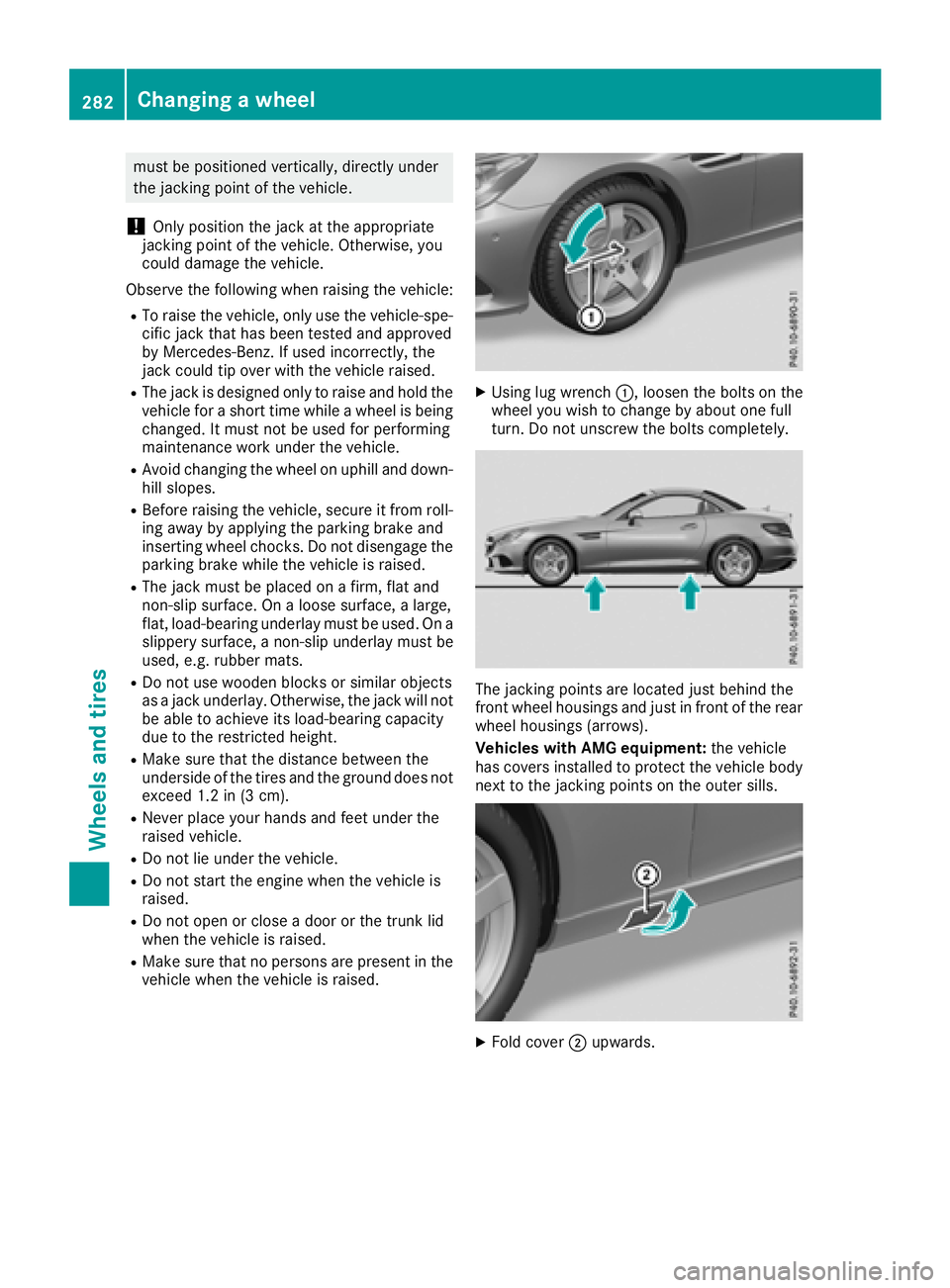
XUsing lug wrench:,loosent he bolts on the
wheely ou wish to change by abouto ne full
turn. Do not unscrew the bolts completely.
The jacking points are located just behind the
front wheelh ousings and just in front of the rear
wheelh ousings (arrows).
Vehicles with AMG equipment: the vehicle
has covers installed to protect the vehicleb ody
next to the jacking points on the outer sills.
XFold cover ;upwards.
282Changing awheel
Wheelsa nd tires
Page 285 of 298
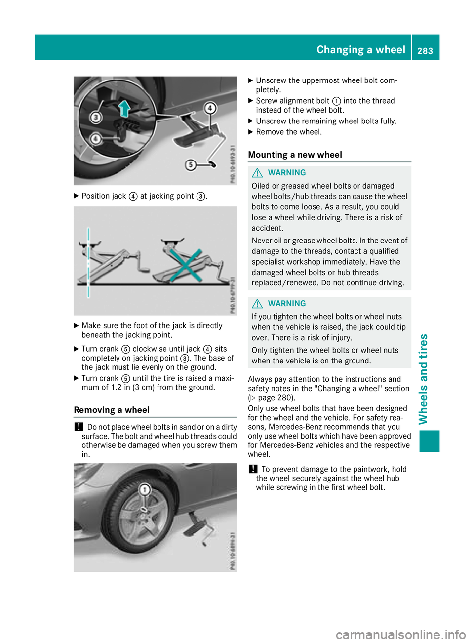
XPosition jack?at jacking point =.
XMake sure the foot of the jack is directly
beneath the jacking point.
XTurn crankAclockwise until jack ?sits
completely on jacking point =.The base of
the jack must lie evenly on the ground.
XTurn crank Auntil the tire is raised amaxi-
mum of 1.2 in (3 cm) from the ground.
Removing awheel
!Do not place wheel bolts in sand or on adirty
surface. The bolt and wheel hub threads could
otherwise be damaged when you screw them
in.
XUnscrew the uppermost wheel bolt com-
pletely.
XScrew alignment bolt :into the thread
instead of the wheel bolt.
XUnscrew the remaining wheel bolts fully.
XRemove the wheel.
Mounting anew wheel
GWARNING
Oiled or greased wheel bolts or damaged
wheel bolts/hub threads can cause the wheel bolts to come loose. As aresult, you could
lose awheel while driving. There is arisk of
accident.
Never oil or grease wheel bolts. In the event of
damage to the threads, contact aqualified
specialist workshop immediately. Have the
damaged wheel bolts or hub threads
replaced/renewed. Do not continue driving.
GWARNING
If you tighten the wheel bolts or wheel nuts
when the vehicle is raised, the jack could tip
over. There is arisk of injury.
Only tighten the wheel bolts or wheel nuts
when the vehicle is on the ground.
Always pay attention to the instruction sand
safety notes in the "Changing awheel" section
(
Ypage 280).
Only use wheel bolts that have been designed
for the wheel and the vehicle. For safety rea-
sons, Mercedes-Benz recommends that you
only use wheel bolts which have been approved for Mercedes-Benz vehicles and the respective
wheel.
!To prevent damage to the paintwork ,hold
the wheel securely against the wheel hub
while screwing in the first wheel bolt.
Changing awheel283
Wheels and tires
Z
Page 286 of 298
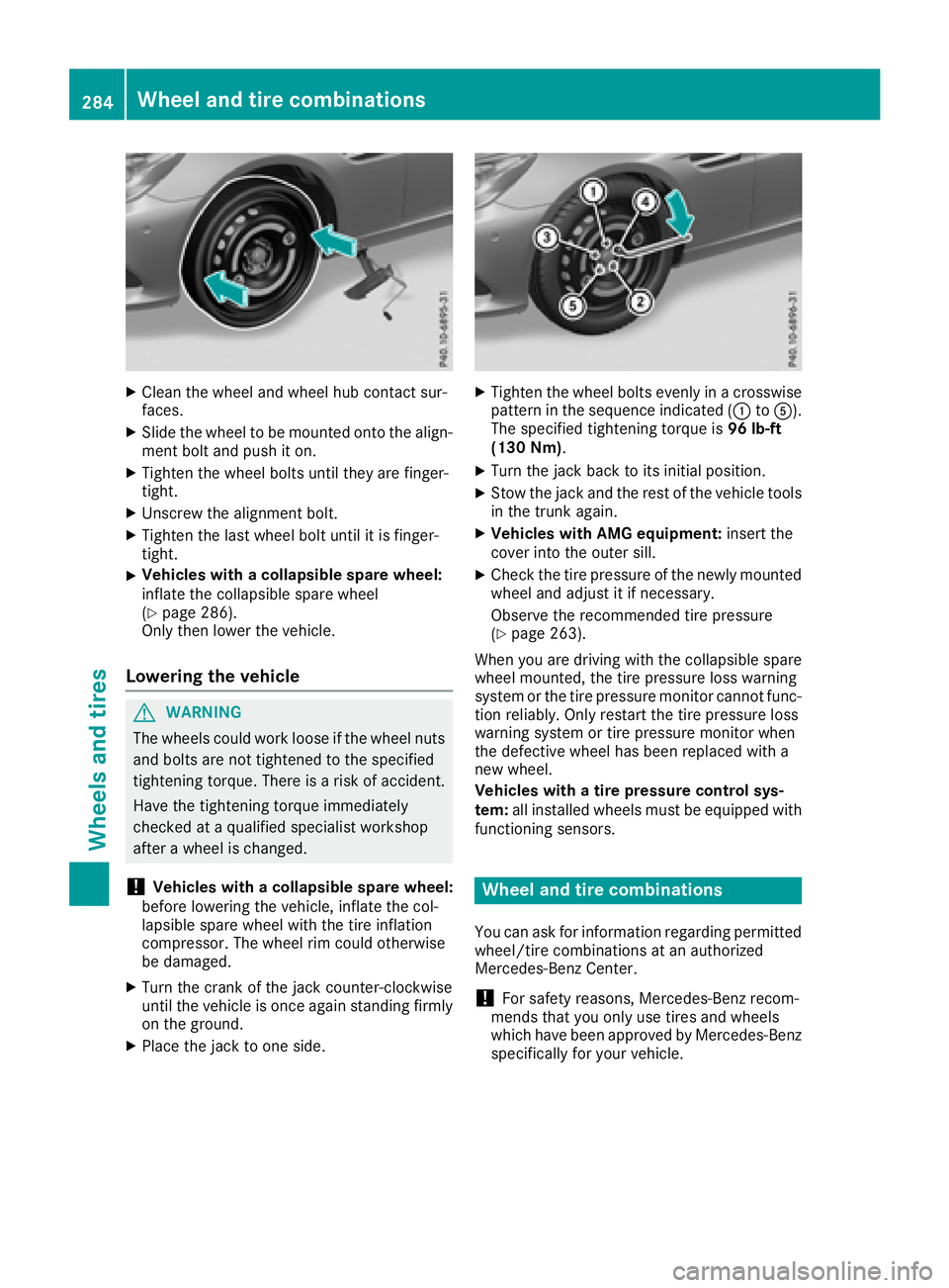
XClean thewheel and wheel hub contact sur-
faces.
XSlid ethe wheel to bemounte dontot he align-
men tbolt and push iton.
XTighte nthe wheel boltsuntilthey are finger-
tight.
XUnscrew th ealignmen tbolt.
XTighte nthe last wheel boltuntil it is finger-
tight.
XVehicles with acollapsible spa rewheel:
inflate th ecollapsible sparewheel
(
Ypage 286).
Only then lower th evehicle .
Lowering th evehicle
GWAR NING
The wheelsc ouldwork looseift hewheel nuts
and boltsare no ttightened to th especifie d
tightening torque. Thereisar iskofa cciden t.
Hav ethe tightening torque immediately
checked at aqualified specialist workshop
after awheel ischanged.
!Vehicles with acollapsible spa rewheel:
before lowering th evehicle ,inflate th ecol-
lapsible sparewheelwiththe tirei nflation
compressor. The wheel rim could otherwise
be damaged.
XTurn th ecrank of th ejackc ounter-clock wise
unt ilth ev ehicle is once again standing firmly
on th eground.
XPlacet hejacktoo neside.
XTighte nthe wheel boltse venlyinac rosswise
pattern inthes equenc eindicated (: toA).
The specifie dtightening torque is 96lb-ft
(1 30 Nm) .
XTurn th ejackb ack to its initial position.
XStow th ejac ka nd th erestoft hevehicle tools
in thet runk again.
XVehicles with AMG equipment: insert the
cover int othe outer sill.
XCheckt hetirep ressureoft henewly mounted
wheel and adjust it if necessary.
Observ ethe recommended tir epressure
(
Ypage 263).
When you are driving withthe collapsible spare
wheel mounte d,thet irep ressurel oss warning
system or th etirep ressurem onitorcanno tfunc-
tio nr eliably. Only restartthe tirep ressurel oss
warning system or tir epressurem onitorwhen
th ed efective wheel has been replace dwitha
ne ww heel.
Vehicles with atirep ressure control sys-
tem: all installed wheelsm ust be equippedwith
functioning sensors.
Wheel and tir ecombinations
You can ask for informatio nregardin gpermitted
wheel/t ire combinations at an authorized
Mercedes-Ben zCenter.
!For safety reasons, Mercedes-Ben zrecom-
men dsthat you only use tires and wheels
whichh ave been approvedbyM ercedes-Benz
specifically for your vehicle.
284Wheel and tir ecombinations
Wheels and tires
Page 287 of 298
These tires have been specially adapted for
use with the control systems, such as ABS or
ESP
®,and are marked as follows:
RMO = Mercedes-Benz Original
RMOE = Mercedes-Benz Original Extended
(tires featuring run-flat characteristics)
RMO1 = Mercedes-Benz Original (only cer-
tain AMG tires)
Mercedes-Benz Original Extended tires may
only be used on wheels that have been spe-
cifically approved by Mercedes-Benz.
Only use tires, wheels or accessories tested
and approved by Mercedes-Benz.C ertain
characteristics, e.g. handling, vehicle noise
emissions or fuel consumption, may other-
wise be adversely affected. In addition, when
driving with aload, tire dimension variations
could cause the tires to come into contact
with the bodywork and axle components .This
could result in damage to the tires or the vehi- cle.
Mercedes-Benz accepts no liability for dam-
age resulting from the use of tires, wheels or
accessories other than those tested and
approved.
Information on tires, wheels and approved
combinations can be obtained from any quali-
fied specialist workshop.
!Retreaded tires are neither tested nor rec-
ommended by Mercedes-Benz,s ince previ-
ous damage cannot alwaysbed etected on
retreaded tires. As aresult, Mercedes-Benz
cannot guarantee vehicle safety if retreaded
tires are mounted. Do not mount used tires if
you have no information about their previous
usage.
The recommended pressures for various oper-
ating conditions can be found:
Ron the Tire and Loading Information placard
on the B-pillar on the driver's side
Rin the tire pressure table on the fuel filler flap
Observe the notes on recommended tire pres-
sures under various operating conditions
(
Ypage 263).
Check tire pressures regularly, and only when
the tires are cold. Comply with the maintenance
recommendations of the tire manufacturer in
the vehicle document wallet. Notes on the vehicle equipment
–alwayse quip
the vehicle:
Rwith tires of the same size on agiven axle (left
and right)
Rwith the same type of tires at agiven time
(summer tires, winter tires, MOExtended
tires)
Exception: it is permissible to mount adiffer-
ent type or make in the event of aflat tire.
Observe t
he "MOExtended tires (tires with
run-flat characteristics)" section
(
Ypage 247).
Vehicles equipped with MOExtended tires are
not equipped with aTIREFIT kit at the factory. It
is therefor erecommended that you additionally
equip your vehicle with aTIREFIT kit if you mount
tires that do not feature run-flat characteristics,
e.g. winter tires. ATIREFIT kit may be obtained
from aqualified specialist workshop.
Emergency sparew heel
Important safety notes
GWARNING
The wheel or tire size as well as the tire type of the spare wheel or emergencys pare wheel
and the wheel to be replaced may differ.
Mountin ganemergencys pare wheel may
severely impair the driving characteristics.
There is arisk of an accident.
To avoid hazardous situations:
Radapt your driving style accordingly and
drive carefully.
Rnever mount more than one spare wheel or
emergencys pare wheel that differs in size.
Ronly useaspare wheel or emergencys pare
wheel of adifferent size briefly.
Rdo not switch ESP®off.
Rhave aspare wheel or emergencys pare
wheel of adifferent size replaced at the
nearest qualified specialist workshop.
Observe that the wheel and tire dimensions
as well as the tire type must be correct.
When using an emergencys pare wheel or spare
wheel of adifferent size, you must not exceed
the maximum speed of 50 mph (80 km/h).
Emergency sparew heel285
Wheels and tires
Z
Page 288 of 298
Snow chains mustnot be mounted on emer-
gency spare wheels.
General notes
You can as kfor information regarding permitted
emergency spare wheel satanauthorized
Mercedes-Benz Center.
You shoul dregularl ycheck the pressure of the
emergency spare wheel ,particularly prior to
long trips, and correct the pressure as neces-
sary (
Ypage 263). The value on the wheel is
valid.
An emergency spare wheel may also be moun-
ted against the direction of rotation. Observe
the time restriction on us easwellast he speed
limitation specified on the emergency spare
wheel.
Replace the tire saftersix years at the latest,
regardless of wear. Thisa lsoa pplies to the
emergency spare wheel.
Wheny ouare driving with the collapsibl espare
wheel mounted, the tire pressure loss warning
system or the tire pressure monitor canno tfunc-
tion reliably. Only restart the tire pressure loss
warning system or tire pressure monitor when
the defectiv ewheel hasb eenr eplaced with a
new wheel.
Vehicles with tire pressure monitor: after
mounting an emergency spare wheel ,the sys-
tem may stil ldisplay the tire pressure of the
removed wheel for afew minutes. The value dis-
played for the mounted emergency spare wheel
is not the same as the current tire pressure of
the emergency spare wheel.
Removin gthe emergencys pare wheel
Vehicles with acolla psibles pare wheel
The collapsibl espare wheel can be found in the
stowag ewellu nder the trunk floor (Ypage 221).
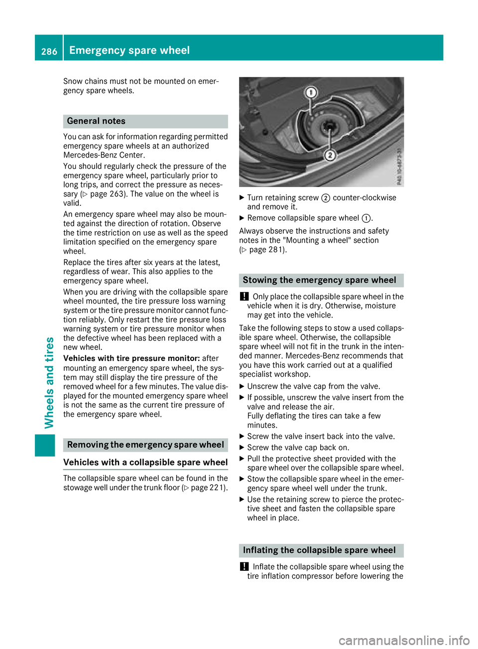
XTurn retaining screw ;counter-clockwise
and remove it.
XRemove collapsibl espare wheel :.
Alway sobserve the instructions and safety
notes in the "Mounting awheel"s ection
(
Ypage 281).
Stowin gthe emergencys pare wheel
!
Only place the collapsibl espare wheel in the
vehicl ewhenitisd ry.O therwise, moisture
may get into the vehicle.
Take the following stepstos towausedc ollaps-
ible spare wheel .Otherwise, the collapsible
spare wheel will not fit in the trunk in the inten-
ded manner. Mercedes-Benz recommendst hat
yo uh avet his work carrie doutataq uali fied
specialist workshop.
XUnscrewt he valve cap from the valve.
XIf possible ,unscrew the valve insert from the
valve and release the air.
Fully deflating the tire scan take afew
minutes.
XScrew the valve insert back into the valve.
XScrew the valve cap back on.
XPull the protectiv esheet provided with the
spare wheel overt he collapsiblespare wheel.
XStow the collapsibl espare wheel in the emer-
gency spare wheel well under the trunk.
XUse the retaining screwtop ierce the protec-
tive sheet and fasten the collapsibl espare
wheel in place.
Inflating the collapsibles pare wheel
!
Inflate the collapsibl espare wheel using the
tire inflation compressor before lowering the
286Emergencys pare wheel
Wheels and tires
Page 289 of 298
vehicle. The wheelrim could otherwise be
damaged.
!Do not operate the tire inflation compressor
for longer than eightm inutes atatime without
ab reak. It may otherwise overheat.
The tire inflation compressorc an be operated
again once it has cooled down.
XMount the collapsible spare wheelasd escri-
bed (Ypag e281).
The collapsible spare wheelm ust be mounted
before it is inflated.
XRemove the tire inflation compressorf rom
the stowage space under the trunk floor
(
Ypag e245).
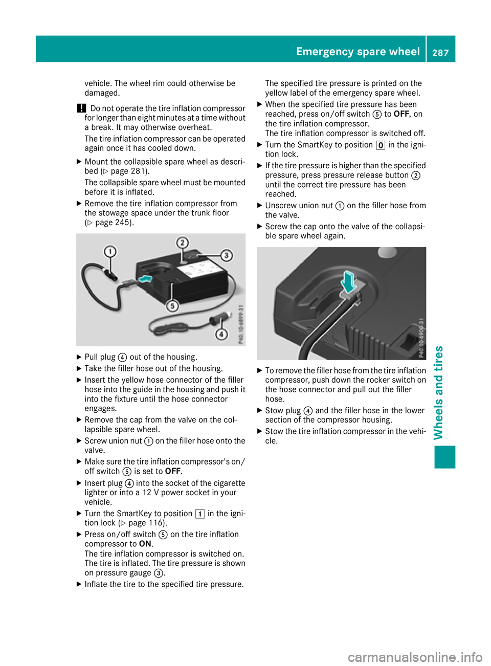
XPullplug ?out of the housing.
XTake the filler hose out of the housing.
XInsert the yellow hose connector of the filler
hose into the guide in the housing and push it
into the fixture until the hose connector
engages.
XRemove the cap from the valve on the col-
lapsibles pare wheel.
XScrew union nut :on the filler hose onto the
valve.
XMake sure the tire inflation compressor's on/
off switch Ais set to OFF.
XInsert plug ?into the socket of the cigarette
lighter or into a12Vpowers ocket in your
vehicle.
XTurn the SmartKey to position 1in the igni-
tion lock (Ypag e116).
XPress on/off switch Aon the tire inflation
compressort oON.
The tire inflation compressoriss witched on.
The tire is inflated. The tire pressure is shown
on pressure gauge =.
XInflate the tire to the specified tire pressure. The specified tire pressure is printed on the
yellow label of the emergency spare wheel.
XWhen the specified tire pressure has been
reached, press on/off switch
AtoOFF,o n
the tire inflation compressor.
The tire inflation compressoriss witched off.
XTurn the SmartKey to positionuin the igni-
tion lock.
XIf the tire pressure is highert han the specified
pressure, press pressure release button ;
until the correct tire pressure has been
reached.
XUnscrew union nut :on the filler hose from
the valve.
XScrew the cap onto the valve of the collapsi-
ble spare wheela gain.
XTo remove the filler hose from the tire inflation
compressor, push down the rocker switch on
the hose connector and pul lout the filler
hose.
XStow plug ?and the filler hose in the lower
section of the compressorh ousing.
XStow the tire inflation compressorint he vehi-
cle.
Emergency spare wheel287
Wheels and tires
Z
Page 297 of 298
Refrigerant instructionlabel
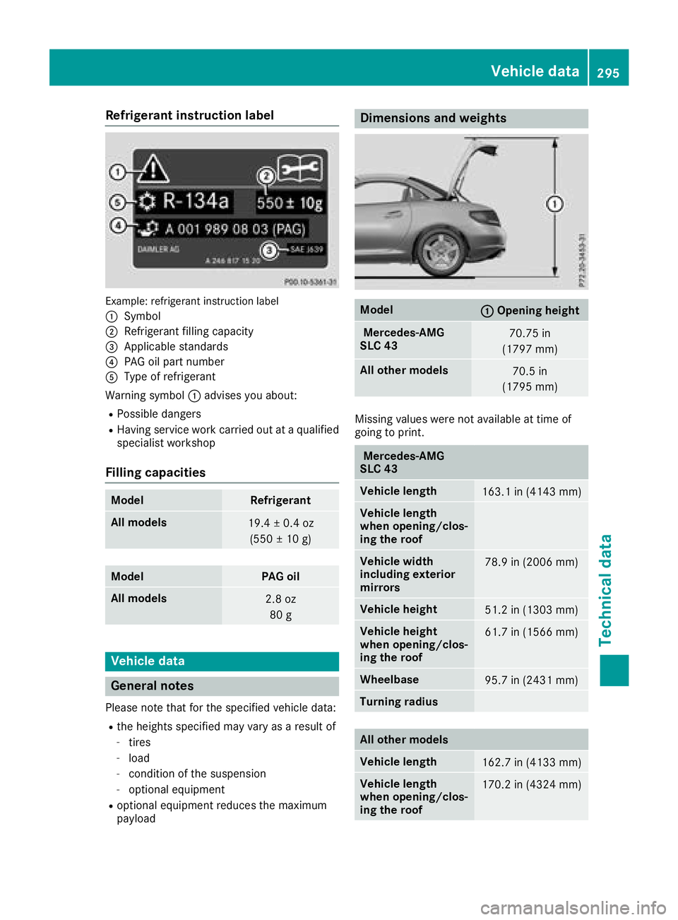
Example:refrigerant instruction label
:
Symbol
;Refrigerant filling capacity
=Applicabl estandards
?PAG oilp artn umber
AType of refrigerant
Warning symbol :advises yo uabout :
RPossible dangers
RHaving service work carrie doutataq uali fied
specialist workshop
Fillin gcapacities
ModelRefrigerant
Allm odels19.4 ±0.4 oz
(550 ±10g )
ModelPAG oil
All models2.8 oz
80 g
Vehicle data
General notes
Please note that for the specified vehicled ata:
Rthe heights specified may vary asaresul tof
-tires
-load
-condition of the suspension
-optionale quipment
Roptionalequipment reduces the maximum
payload
Dimensions and weights
Model:Opening height
Mercedes-AMG
SLC 4370.75 in
(1797 mm)
All other models70.5 in
(1795 mm)
Missing values were not available at time of
going to print.
Mercedes-AMG
SLC 43
Vehicle length163.1 in (4143 mm)
Vehicle length
whe nopening/clos-
ing the roof
Vehicle width
including exterior
mirrors78.9 in (2006 mm)
Vehicle height51.2 in (1303 mm)
Vehicle height
whe nopening/clos-
ing the roof61.7 in (1566 mm)
Wheelbase95.7 in (2431 mm)
Turning radius
All other models
Vehicle length162.7 in (4133 mm)
Vehicle length
whe nopening/clos-
ing the roof170.2 in (4324 mm)
Vehicle data295
Technical data
Z
Page 298 of 298
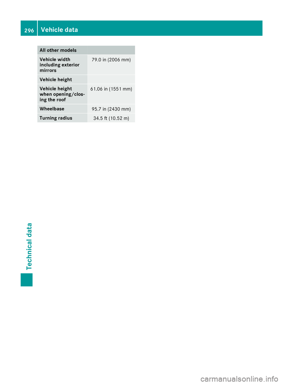
All othermodels
Vehicle width
includin gexteri or
mir rors79.0 in(2006 mm)
Vehicle height
Vehicle height
when opening/clos-
ing th eroof61.0 6in( 1551m m)
Wheelbase95.7 in(2430 mm)
Tu rning radius34.5 ft (10.52m)
296Vehicle data
Technical data