2018 MERCEDES-BENZ SLC ROADSTER key
[x] Cancel search: keyPage 257 of 298
XMake sure that the ignition is switched off. All indicator lamps in the instrumentcluster must be
off. When using the SmartKey, turn the SmartKey to position uin the ignition lock and remove it
(
Ypage 116).
XSwitch off all electrical consumers, e.g. rear window defroster, lighting, etc.
XOpen the hood.
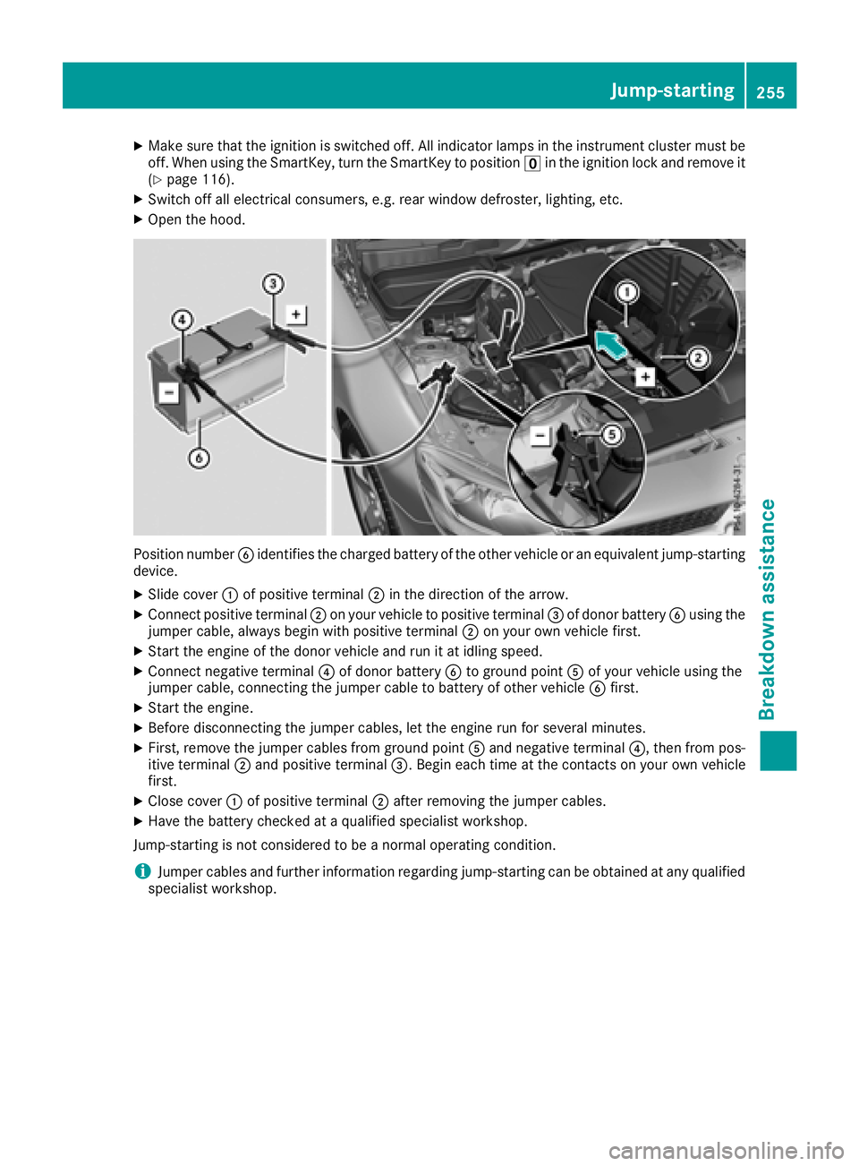
Position number Bidentifies the charged battery of the other vehicle or an equivalent jump-starting
device.
XSlide cover :of positive terminal ;in the direction of the arrow.
XConnect positive terminal ;on your vehicle to positive terminal =of donor battery Busing the
jumper cable, always begin with positive terminal ;on your own vehicle first.
XStart the engine of the donor vehicle and run it at idling speed.
XConnect negative terminal ?of donor battery Bto ground point Aof your vehicle using the
jumper cable, connecting the jumper cable to battery of other vehicle Bfirst.
XStart the engine.
XBefore disconnecting the jumper cables, let the engine run for several minutes.
XFirst, remove the jumper cables from ground point Aand negative terminal ?,then from pos-
itive terminal ;and positive terminal =.Begin each time at the contacts on your own vehicle
first.
XClose cover :of positive terminal ;after removing the jumper cables.
XHave the battery checked at aqualified specialist workshop.
Jump-starting is not considered to be anormal operating condition.
iJumper cables and further information regarding jump-starting can be obtained at any qualified
specialist workshop.
Jump-starting255
Breakdown assistance
Z
Page 258 of 298
Towingand tow-starting
Important safety notes
GWARNING
When towing or tow-startin ganotherv ehicle
and its weight is greate rthant he permissible
gross weight of your vehicle, the:
Rthe towing ey ecould detach itself
Rthe vehicle/trailer combinatio ncould roll-
over.
There is ariskofana ccident.
When towing or tow-startin ganotherv ehicle,
its weight shoul dnot be greate rthant he per-
missibl egross weight of your vehicle.
Detail sonthe permissibl egross vehicl eweigh t
of your vehicl ecan be found on the vehicl eide n-
tification plate (
Ypage 289).
!When Activ eBrake Assist, Distance Pilot
DISTRONICort he HOLD functio nisa ctivated,
the vehicl ebrakes automaticall yincertain
situations.
To avoi ddamag etothe vehicle, deactivate
these system sinthe following or similar sit-
uations:
Rwhen towing the vehicle
Rin the car wash
!Onlys ecurethe tow rop eortow ba ratthe
towing eyes. Otherwise, the vehicl ecould be
damaged.
!Do not us ethe towing ey efor recovery, this
could damage the vehicle. If in doubt, recover
the vehicl ewithac rane.
!When towing ,pulla wa yslowly and
smoothly. If the tractiv epower is too high, the
vehicles could be damaged.
!Do not tow with sling-typ eequipment .This
could damage the vehicle.
!When towing away vehicles with KEYLESS-
GO ,use the key instea dofthe Start/Stop
button. The automatic transmission mayo th-
erwis eshift to position jwhen yo uopent he
driver's or front-passenge rdoor, which could
damage the transmission.
!Make sure thatt he electricparkin gb rake is
released .Ifthe electri cparkin gbrake is faulty,
visit aquali fied specialis tworkshop.
!The vehicl ecan be towed amaximum of
30 miles (50km). The towing spee dof30mph
(50 km/h )mustn ot be exceeded.
If the vehicl ehasto be towed mor ethan
30 miles (50km), the entire vehicl emustb e
raised and transported.
!If yo utow or tow-start anotherv ehicle, its
weight must not exceed the maximum per-
missibl egross vehicl eweigh tofy ourvehicle.
It is better to have the vehicl etransporte dthan
to have it towed away.
The automatic transmission must be in position
i when the vehicl eisbeing towed away.
The battery must be connected and charged.
Otherwise, you:
Rcanno tturnt he SmartKeytop osition 2in
the ignition lock.
Rcanno tshift the automatic transmission to
position i.
Deactivate the automatic locking featur ebef
o
re
the vehicl eistowed (Ypage 173).Y oucould
otherwis ebelocked ou twhenp ushing or towing
the vehicle.
Installing/removin gthe towin geye
Installing the towin geye
GWARNING
The exhaust tai lpipem aybe ver yhot. There is
ar iskofb urns when removing the rea rcover.
Do not touch the exhaust pipe .Tak ep articular
car ew henr emoving the rea rcover.
256Towin gand tow-starting
Breakdow nassistance
Page 259 of 298
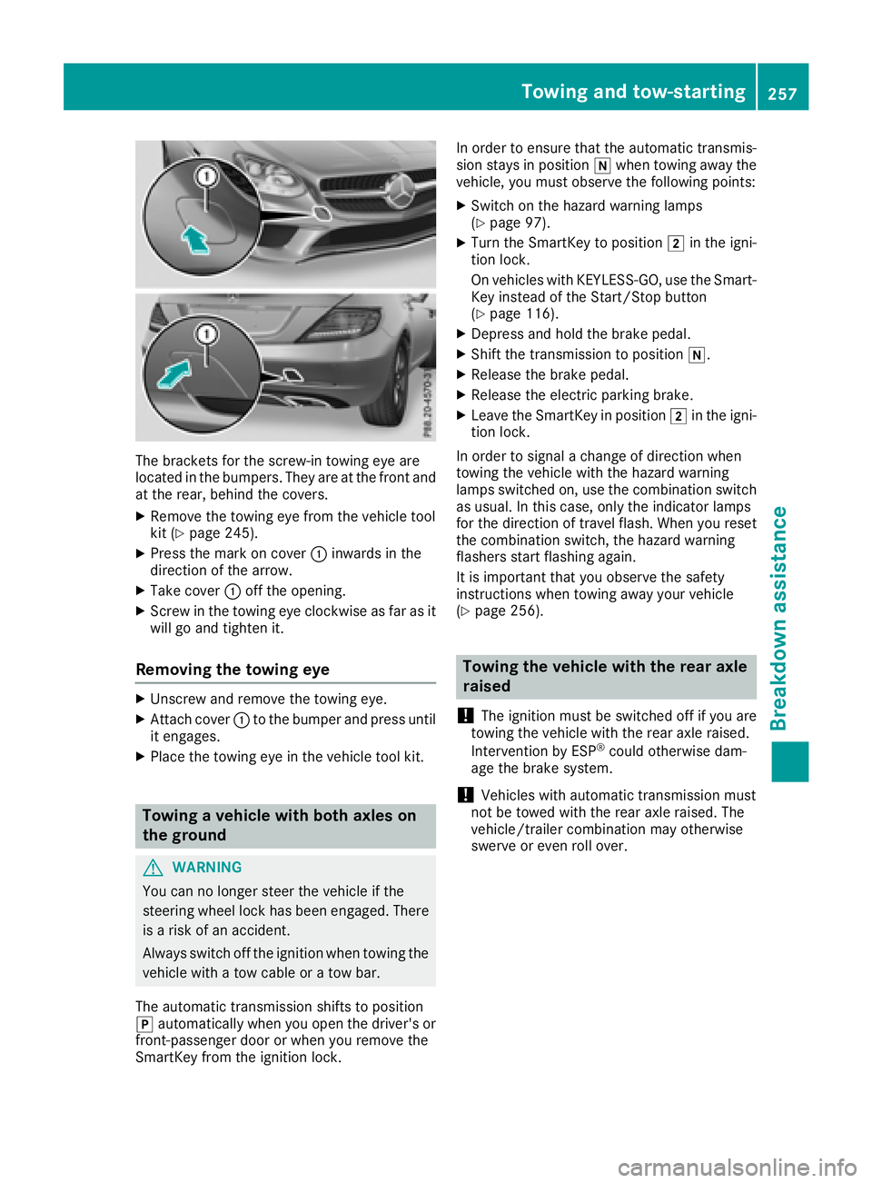
The bracketsfor the screw-in towing eye are
located in the bumpers. They are at the front and
at the rear, behind the covers.
XRemove the towing eye from the vehicle tool
kit (Ypage 245).
XPress the mark on cover :inwards in the
direction of the arrow.
XTake cover :off the opening.
XScrew in the towing eye clockwise as far as it
will go and tighten it.
Removing the towing eye
XUnscrew and remove the towing eye.
XAttach cover :to the bumper and press until
it engages.
XPlace the towing eye in the vehicle tool kit.
Towing avehicle with both axles on
the ground
GWARNING
You can no longer steer the vehicle if the
steerin gwheel lock has been engaged. There
is ar isk of an accident.
Always switch off the ignition when towing the
vehicle with atow cable or atow bar.
The automatic transmission shifts to position
j automatically when you open the driver's or
front-passenger door or when you remove the
SmartKey from the ignition lock. In order to ensure that the automatic transmis-
sion stays in position
iwhen towing away the
vehicle, you must observe the following points:
XSwitch on the hazard warning lamps
(Ypage 97).
XTurn the SmartKey to position 2in the igni-
tion lock.
On vehicles with KEYLESS-GO, use the Smart-
Key instead of the Start/Stop button
(
Ypage 116).
XDepress and hold the brake pedal.
XShift the transmission to position i.
XRelease the brake pedal.
XRelease the electric parking brake.
XLeave the SmartKey in position2in the igni-
tion lock.
In order to signal achange of direction when
towing the vehicle with the hazard warning
lamps switched on, use the combination switch
as usual. In this case, only the indicator lamps
for the direction of travel flash. When you reset
the combination switch, the hazard warning
flashers start flashing again.
It is important that you observe the safety
instructions when towing away your vehicle
(
Ypage 256).
Towing the vehicle with the rear axle
raised
!
The ignition must be switched off if you are
towing the vehicle with the rear axle raised.
Intervention by ESP
®could otherwise dam-
age the brake system.
!Vehicles with automatic transmission must
not be towed with the rear axle raised. The
vehicle/trailer combination may otherwise
swerve or even roll over.
Towing and tow-starting257
Breakdown assistance
Z
Page 260 of 298
Transporting the vehicle
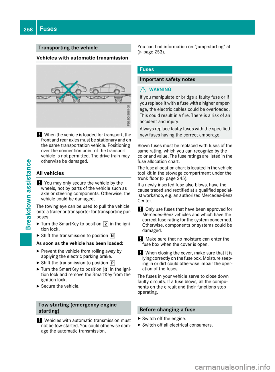
Vehicle switha utomatic transmission
!When the vehicl eisloaded for transport, the
front and rea raxles must be stationar yand on
the same transportatio nvehicle. Positioning
ove rthe connectio npoint of the transport
vehicl eisnot permitted .The drive train may
otherwis ebedamaged .
Allv eh icles
!Youm ayonl ysecur ethe vehicl ebythe
wheels ,not by parts of the vehicl esucha s
axl eors teerin gcomponents. Otherwise, the
vehicl ecould be damaged.
The towing ey ecan be used to pull the vehicle
onto atrailer or transporte rfor transporting pur-
poses.
XTurn the SmartKeytop osition 2in the igni-
tio nlock.
XShift the transmission to position i.
As soon as the vehicle has been loaded:
XPrevent the vehicl efromr olling away by
applying the electri cparkin gb rake.
XShift the transmission to position j.
XTurn the SmartKeytoposition uin the igni-
tio nlocka nd remove the SmartKeyf romthe
ignition lock.
XSecure the vehicle.
Tow-starting (emergency engine
starting)
!
Vehicles with automatic transmission must
not be tow-started .You could otherwis edam -
ag et he automatic transmission. Yo
uc an find informatio non"Jump-starting "at
(
Ypage 253).
Fuses
Important safety notes
GWARNING
If yo umanipulate or bridg eafaulty fuse or if
yo ur eplace it with afusew ithah ighe ramper -
age, the electri ccable scould be overloaded.
Thi scould resul tinafire. There is ariskofa n
accident and injury.
Alway sreplace faulty fuses with the specified
new fuses havin gthe correct amperage.
Blown fuses must be replaced with fuses of the
same rating ,which yo ucan recognize by the
color and value. The fuse rating sarelisted in the
fuse allocation chart.
The fuse allocation chart is locate dinthe vehicle
tool kit in the stowag ecompartment under the
trunk floor (
Ypage 245).
If an ewly inserte dfusea lsob lows ,havet he
cause traced and rectifie dataqualified special-
is tw orkshop ,e.g.ana uthorize dMercedes-Benz
Center.
!Onlyu sefuses thath aveb eena pproved for
Mercedes-Benz vehicles and which have the
correct fuse rating for the system concerned.
Otherwise, components or system scould be
damaged.
!Make sure thatnom oisture can enterthe
fuse bo xwhent he cove risopen.
!When closing the cover, make sure thatiti s
lying correctl yonthe fuse box. Moisture seep-
ing in or dirt could otherwis eimpai rthe oper-
atio
n of the fuses.
The fuses in your vehicl eserve to close down
faulty circuits. If afuseb lows ,allthe compo-
nents on the circui tand their functions stop
operating.
Before changin gafuse
XSwitch off the engine.
XSwitch off al lelectrical consumers.
258Fuses
Breakdow nassistance
Page 261 of 298
XMake sure that the ignition is switched off
(Ypage 116).
or
XWhen using the SmartKey, turn the SmartKey to position uin the ignition lock and remove
it (
Ypage 116).
XSecure the vehicle against rolling away
(Ypage 131).
All indicator lamps in the instrumen tcluster
must be off.
The fuses are located in various fuse boxes:
RFuse box in the engine compartmentont he
left-hand side of the vehicle, when viewed in
the direction of travel
RFuse box in the trunk
Fuse box in the engine compartment
i
Observe the "Important safety notes" sec-
tion (Ypage 258).
GWARNING
When the hood is open and the windshield
wipers are set in motion, you can be injured by
the wiper linkage. There is arisk of injury.
Always switch off the windshield wipers and
the ignition before opening the hood.
XMake sure that the windshield wipers are
turned off.
XOpen the hood.
XUse adry cloth to remove any moisture from
the fuse box.
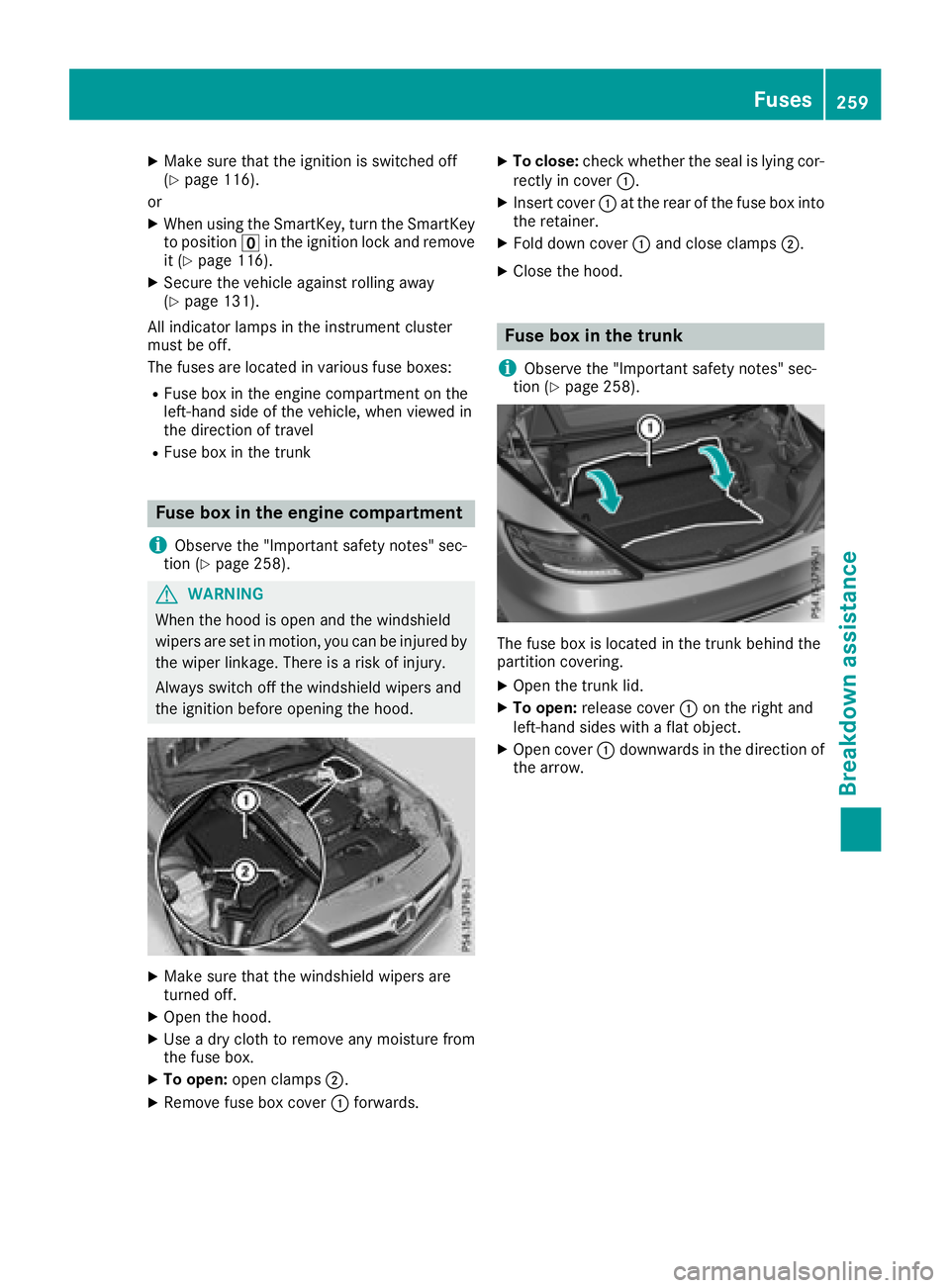
XTo open: open clamps ;.
XRemove fuse box cover :forwards.
XTo close: check whether the seal is lying cor-
rectly in cover :.
XInsert cover:at the rear of the fuse box into
the retainer.
XFold down cover :and close clamps ;.
XClose the hood.
Fuse box in the trunk
i
Observe the "Important safety notes" sec-
tion (Ypage 258).
The fuse box is located in the trunk behind the
partition covering.
XOpen the trunk lid.
XTo open: release cover :on the right and
left-hand sides with aflat object.
XOpen cover :downwards in the direction of
the arrow.
Fuses259
Breakdown assistance
Z
Page 269 of 298
Important safety notes
The tire pressurewarning system does no twarn
you of an incorrectl yset tire pressure. Observ e
th en otes on th erecommended tire pressur e
(
Ypage 263).
The tire pressur eloss warning does no treplace
th en eedtor egularly chec kthe tire pressure. An
eve nloss of pressur eonseveral tires at th e
sam etimec anno tbed etecte dbythetire pres-
sur eloss warning system.
The tire pressur emonitor is no table to warn you
of as udde nloss of pressure, e.g. if th etirei s
penetrated by aforeign object. In th eevent of a
sudde nloss of pressure, brin gthe vehicl etoa
halt by braking carefully. Avoid abrup tsteering
movements.
The function of th etirep ressur eloss warning
system is limite dordelayedif:
Rsnow chain sare mounte donyour vehicle's
tires .
Rroad condition sare wintry.
Ryou are driving on san dorgravel.
Ryou adopt averys port ydriving style (corner-
ing at high speeds or driving wit hhigh rates of
acceleration).
Ryou driv ewithah eavyload.
Restarting th etirep ressure loss warn-
ing system
Restart th etirep ressur eloss warning system if
you have :
Rchanged th etirep ressur e
Rchanged th ewheels or tires
Rmounte dnew wheels or tires
XBefore restarting ,makes uret hatthe tire
pressures are set properly on all four tires for
th er espective operating conditions.
The recommended tire pressur ecan be foun d
on th eTirea nd Loading Information placard
on th eB-pillar .Additionally, atirep ressur e
table is attached to th efuel filler flap .The tire
pressur eloss warning system can only giv e
reliable warning sifyou have set th ecorrect
tire pressure. If an incorrec ttirep ressur eis
set ,the se incorrec tvalue swill be monitored.
XAlsoo bserv ethe note sint hesection on tire
pressures (Ypage 263).
XMakesuret ha tthe SmartKey is in position 2
in th eignition loc k(Ypage 116).
XPress the= or; buttononthesteering
whee ltos elect th eServ.menu.
XPress th e9 or: buttontos elect
Tir ePressure.
XPress th ea button.
The Run Fla tIndicator Active Press
'OK'toR estartmessage appear sinthe
multifunction display.
If you wish to confirm th erestart :
XPress th ea button.
The TirePressure Now OK?message
appear sinthemultifunction display.
XPress th e9 or: buttontos electYes.
XPress th ea button.
The Run Fla tIndicator Restartedmes -
sage appear sinthemultifunction display.
Afte rateach-in period, th etirep ressur eloss
warning system will monitor th eset tire pres-
sures of all four tires .
If you wish to cancel th erestart :
XPress th e% button.
or
XIf th eTir ePressure Now OK?message
appears, use th e9 or: buttonto
select Cancel
.
XPress th ea button.
The tire pressur evalue sstoredatt helast
restar twill continue to be monitored.
Tire pressure monitor
General notes
If at irep ressur emonitor is installed, th evehi-
cle's wheels hav esensor sthatm onitor th etire
pressures in all four tires .The tire pressur emon-
itor warn syou if th epressur edrops in on eor
mor eoft hetires .The tire pressur emonitor only
function sifthecorresponding sensor sare
installed in all wheels.
Information on tire pressures is displayed in th e
multifunction display. Afte rafew minute sof
driving ,the curren ttirep ressur eofeacht irei s
shown in th eServ.
men uoft hemultifunction
display.
Tire pressure267
Wheels and tires
Z
Page 271 of 298
The tire pressure monitor hasayellow warning
lamp in the instrument cluster for indicating
pressure loss or amalfunction. Whether the
warning lamp flashes or lights up indicates
whether atire pressure is too low or the tire
pressure monitor is malfunctioning:
Rif the warning lamp is lit continuously, the tire
pressure on one or more tires is significantly
too low. The tire pressure monitor is not mal- functioning.
Rif the warning lamp flashes for approximately
am inute and then remains lit constantly, the
tire pressure monitor is malfunctioning.
In addition to the warning lamp, amessage
appears in the multifunction display.O bserve
the information on display messages
(
Ypage 196).
It may take up to ten minutes for amalfunction
of the tire pressure monitor to be indicated. A
malfunction will be indicated by the tire pres-
sure warning lamp flashing for approximately
one minute and then remaining lit. When the
malfunction has been rectified, the tire pressure
warning lamp goes out after afew minutes of
driving.
The tire pressure values indicated by the on-
board computer may differ from those meas-
ured at agas station with apressure gage. The
tire pressures shown by the on-board computer
refer to those measured at sea level. At high
altitudes, the tire pressure values indicated by a pressure gage are higher than those shown by
the on-board computer. In this case, do not
reduce the tire pressures.
The operation of the tire pressure monitor can
be affected by interferenc efrom radio transmit-
ting equipment (e.g. radio headphones, two-way
radios) that may be being operated in or near the vehicle.
Checking the tire pressur eelectroni-
cally
XMake sure that the SmartKey is in position 2
(Ypage 116) in the ignition lock.
XPress the =or; button on the steering
wheel to select the Serv.menu.
XPress the9or: button to select
Tire Pressure.
XPress a.
The current tire pressure of each tire is shown
in the multifunction display. If the vehicle has been parked for over
20 minutes, the
Tire pressure will be
displayed after driving afew minutesmessage appears.
After ateach-in process, the tire pressure mon-
itor automatically detect snew wheels or new
sensors. As long as aclear allocation of the tire
pressure value to the individual wheels is not
possible, the Tire
PressureMonitorActivedisplay message is shown instead of the tire
pressure display.T he tire pressures are already
being monitored.
If an emergencys pare wheel is mounted, the
system may continue to show the tire pressure
of the wheel that has been removed for afew
minutes. Be aware that the value displayed for
the position where the emergencys pare wheel
is fitted is not the same as the current tire pres-
sure of the emergencys pare wheel.
Tire pressuremonitor warning mes-
sages
The tire pressure monitor detect sapressure
loss in one or more tires:
RIf the tire pressure monitor detect sapressure
loss in one or more tires, awarning message
is shown in the multifunction display.T he yel-
low tire pressure warning lamp then lights up.
RIf the Please Correct Tire Pressuremessage appears in the multifunction display,
the tire pressure in at least one tire is too low.
The tire pressure must be corrected when the
opportunit yarises.
RIf the Check Tiresmessage appears in the
multifunction display,t he tire pressure in at
least one tire has dropped significantly. The
tires must be checked.
RIf the WarningTireMalfunctionmessage
appears in the multifunction display,t he tire
pressure in at least one tire has dropped sud-
denly. The tires must be checked.
Observe the instructions and safety notes in the
display messages in the "Tires" section
(
Ypage 196).
If the wheel positions on the vehicle are rotated,
the tire pressures may be displayed for the
wrong positions for ashort time. This is rectified
after afew minutes of driving, and the tire pres-
sures are displayed for the correctp ositions.
Tirepressure269
Wheels and tires
Z
Page 272 of 298
Restarting the tire pressure monitor
Whenyourestart the tire pressure monitor, all
existing warning messages are deleted and the
warning lamps go out. The monitor uses the cur-
rentlys et tire pressures as the reference values
for monitoring. In most cases, the tire pressure
monitor will automaticall ydetect the new refer-
ence value safteryou have changed the tire
pressure. However, yo ucan also set reference
value smanually as described here. The tire
pressure monitor then monitors the new tire
pressure values.
XSet the tire pressure to the value recommen-
ded for the corresponding driving situation on
the Tire and Loading Information placard on
the driver'ss ideB -pillar (
Ypage 263).
Additiona ltire pressure value sfor different
load scan also be found on the tire pressure
table on the inside of the fue lfille rflap
(
Ypage 263).
XMake sure that the tire pressure is correct on
al lf ourw heels.
XEnsur ethat the SmartKey is in position 2in
the ignition lock.
XPress the =or; button on the steering
wheel to select the Serv.menu.
XPress the9or: button to select
Tire Pressure.
XPress a.
The multifunction display shows the current
tire pressure for the individual tire sorthe
Tire pressure will be displayed
afterd rivingafew minutesmessage.
XPress the :button.
The UseCurrentPressuresasNewRef‐erenceValuesmessage appears in the mul-
tifunction display.
If you wish to confirm the restart:
XPress a.
The TirePress.MonitorRestartedmes-
sage appears in the multifunction display.
After driving for afew minutes, the system
checks whethert he current tire pressures are
within the specified range. The new tire pres-
sures are then accepted as reference values
and monitored.
If you wish to cance lthe restart:
XPress %.
The tire pressure value sstoredatt he last
restart will continu etobemonitored.
Radio type approval for the tire pres-
sure monitor
CountryRadio type approval number
USAFCC ID: MRXMW2433A
FCCIC ID:MRXGG4 Thisd evice
complies with part 15 of the FCC
rules and with license exempt
RSS standard sofIndustry Can-
ada. Operation is subject to the
following conditions .(1) This
device may not cause harmful
interference, and (2) Thisd evice
mus taccept any interference
received, including interference
that may cause undesired oper-
ation. Le present appareile st
conforme d'industrieC anada
applicables au xappar eils radio
exempts de licence. L'exploita-
tion est authorisee au xdeuxc on-
ditions suivantes. (1) L'appareil
ne doi tpas produire de brouil-
lage, et (2) L'autisatue rdel'ap-
pareild oita ccepter toutb rouil-
lage radioelectriqu esubi, meme
si le brouillag eest susceptible
d'e ncompromettre le fonc-
tionnement. WARNING:C hanges
or modifications not expressly
approved by the party responsi-
bl ef or compliance could voidt he
user'sa uthority to operate the
equipment. The term "IC:" before the radio certification number
only signifies Canad atechnical
specifications were met.
FCC ID:MRXMC34MA4 This
device complies with part 15 of
the FCC rules and with license
exempt RSS standard sofIndus-
try Canada. Operation is subject
to the following conditions .(1)
Thisd evice may not cause harm-
ful interference, and (2) This
device mus taccept any interfer-
ence received, inclu
ding interfer-
ence that may cause undesired
operation. Le present appareil
est conforme d'industrieC anada
applicables au xappar eils radio
exempts de licence. L'exploita-
tion est authorisee au xdeuxc on-
ditions suivantes. (1) L'appareil
270Tire pressure
Wheel sand tires