2018 MERCEDES-BENZ SLC ROADSTER ECU
[x] Cancel search: ECUPage 268 of 298
Avoidtire pressures thata retoo high in al lthe
tires, including the spare wheel.
Overinflated tire smay:
Rincrease the braking distance
Radversel yaffect handling
Rwear excessivel yand/or unevenly
Rhave an adverse effect on rid ecomfort
Rbe more susceptibl etodamage
Maximum tire pressures
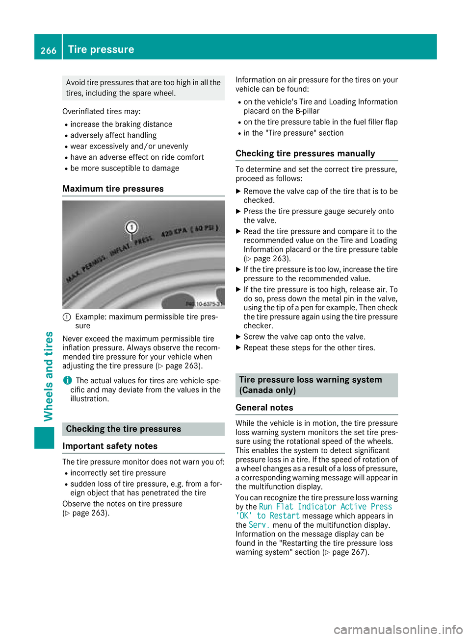
:Example: maximu mpermissibl etire pres-
sure
Never exceed the maximu mpermissibl etire
inflation pressure. Alway sobserve the recom-
mended tire pressure for your vehicl ewhen
adjusting the tire pressure (
Ypage 263).
iThe actual values for tire sarevehicle-spe-
cifi cand mayd eviate from the values in the
illustration.
Checkin gthe tire pressures
Important safety notes
The tire pressure monitor does not warn yo uof:
Rincorrectly set tire pressure
Rsudden loss of tire pressure, e.g .from afor-
eign object thath aspenetrated the tire
Observ ethe notes on tire pressure
(
Ypage 263). Informatio
nonairpressure for the tire sonyour
vehicl ecan be found:
Ron the vehicle's Tire and Loading Information
placard on the B-pillar
Ron the tire pressure table in the fuel fille rflap
Rin the "Tire pressure" section
Checkin gtire pressuresm anually
To determine and set the correct tire pressure,
proceedasfollows:
XRemove the valve cap of the tire thati stobe
checked.
XPress the tire pressure gaug esecurel yonto
the valve.
XRead the tire pressure and compar eittothe
recommende dvalue on the Tire and Loading
Informatio nplacard or the tire pressure table
(
Ypage 263).
XIf the tire pressure is too low, increase the tire
pressure to the recommende dvalue.
XIf the tire pressure is too high, release air. To
do so, press down the meta lpinin the valve,
using the tip of apen for example. The ncheck
the tire pressure agai nusing the tire pressure
checker.
XScrew the valve cap onto the valve.
XRepeat thes estepsf or the othe rtires.
Tire pressure loss warning system
(Canada only)
General notes
While the vehicl eisinmotion, the tire pressure
loss warning system monitors the set tire pres-
sure using the rotational speed of the wheels.
Thi senables the system to detect significant
pressure loss in atire .Ift he speed of rotatio nof
aw heel changesasa resultofa loss of pressure,
ac orresponding warning message will appear in
the multifunctio ndisplay.
Yo uc an recognize the tire pressure loss warning
by the Run FlatI ndicator Active Press
'OK'toRestartmessage which appear sin
the Serv.menu of the multifunctio ndisplay.
Informatio nonthe message display can be
found in the "Restarting the tire pressure loss
warning system "sectio n(
Ypage 267).
266Tire pressure
Wheel sand tires
Page 272 of 298
Restarting the tire pressure monitor
Whenyourestart the tire pressure monitor, all
existing warning messages are deleted and the
warning lamps go out. The monitor uses the cur-
rentlys et tire pressures as the reference values
for monitoring. In most cases, the tire pressure
monitor will automaticall ydetect the new refer-
ence value safteryou have changed the tire
pressure. However, yo ucan also set reference
value smanually as described here. The tire
pressure monitor then monitors the new tire
pressure values.
XSet the tire pressure to the value recommen-
ded for the corresponding driving situation on
the Tire and Loading Information placard on
the driver'ss ideB -pillar (
Ypage 263).
Additiona ltire pressure value sfor different
load scan also be found on the tire pressure
table on the inside of the fue lfille rflap
(
Ypage 263).
XMake sure that the tire pressure is correct on
al lf ourw heels.
XEnsur ethat the SmartKey is in position 2in
the ignition lock.
XPress the =or; button on the steering
wheel to select the Serv.menu.
XPress the9or: button to select
Tire Pressure.
XPress a.
The multifunction display shows the current
tire pressure for the individual tire sorthe
Tire pressure will be displayed
afterd rivingafew minutesmessage.
XPress the :button.
The UseCurrentPressuresasNewRef‐erenceValuesmessage appears in the mul-
tifunction display.
If you wish to confirm the restart:
XPress a.
The TirePress.MonitorRestartedmes-
sage appears in the multifunction display.
After driving for afew minutes, the system
checks whethert he current tire pressures are
within the specified range. The new tire pres-
sures are then accepted as reference values
and monitored.
If you wish to cance lthe restart:
XPress %.
The tire pressure value sstoredatt he last
restart will continu etobemonitored.
Radio type approval for the tire pres-
sure monitor
CountryRadio type approval number
USAFCC ID: MRXMW2433A
FCCIC ID:MRXGG4 Thisd evice
complies with part 15 of the FCC
rules and with license exempt
RSS standard sofIndustry Can-
ada. Operation is subject to the
following conditions .(1) This
device may not cause harmful
interference, and (2) Thisd evice
mus taccept any interference
received, including interference
that may cause undesired oper-
ation. Le present appareile st
conforme d'industrieC anada
applicables au xappar eils radio
exempts de licence. L'exploita-
tion est authorisee au xdeuxc on-
ditions suivantes. (1) L'appareil
ne doi tpas produire de brouil-
lage, et (2) L'autisatue rdel'ap-
pareild oita ccepter toutb rouil-
lage radioelectriqu esubi, meme
si le brouillag eest susceptible
d'e ncompromettre le fonc-
tionnement. WARNING:C hanges
or modifications not expressly
approved by the party responsi-
bl ef or compliance could voidt he
user'sa uthority to operate the
equipment. The term "IC:" before the radio certification number
only signifies Canad atechnical
specifications were met.
FCC ID:MRXMC34MA4 This
device complies with part 15 of
the FCC rules and with license
exempt RSS standard sofIndus-
try Canada. Operation is subject
to the following conditions .(1)
Thisd evice may not cause harm-
ful interference, and (2) This
device mus taccept any interfer-
ence received, inclu
ding interfer-
ence that may cause undesired
operation. Le present appareil
est conforme d'industrieC anada
applicables au xappar eils radio
exempts de licence. L'exploita-
tion est authorisee au xdeuxc on-
ditions suivantes. (1) L'appareil
270Tire pressure
Wheel sand tires
Page 281 of 298
Speed rating
The speed rating is part of the tire identification.It specifies the speed range for which the tire is
approved.
GVW (Gross Vehicle Weight)
The gross vehicle weight includes the weight of the vehicle including fuel, tools, the spare wheel,
accessories installed, occupants, luggage and
the drawbar noseweight, if applicable. The gross
vehicle weight must not exceed the gross vehi-
cle weight rating GVWR as specified on the vehi- cle identification plate on the B-pillar on the
driver's side.
GVWR (Gross Vehicle Weight Rating)
The GVWR is the maximum permissible gross
weight of afully loaded vehicle (the weight of the
vehicle including all accessories, occupants,
fuel, luggage and the drawbar noseweight, if
applicable). The gross vehicle weight rating is
specified on the vehicle identification plate on
the B-pillar on the driver's side.
Maximu mloaded vehicle weight
The maximum weight is the sum of:
Rthe curb weight of the vehicle
Rthe weight of the accessories
Rthe load limit
Rthe weight of the factory installed optional
equipment
Kilopascal (kPa)
Metric unit for tire pressure. 6.9 kPa corre-
sponds to 1psi. Another unit for tire pressure is
bar. 100 kilopascals (kPa) are the equivalent of
1b ar.
Load index
In addition to the load-bearing index, the load
index may also be imprinted on the sidewallo f
the tire. This specifies the load-bearing capacity
more precisely.
Curb weight
The weight of avehicle with standard equipment
including the maximum capacity of fuel, oil and
coolant. It also includes the air-conditioning sys-
tem and optional equipment if these are instal-
led in the vehicle, but does not include passen-
gers or luggage.
Maximu mload rating
The maximum load rating is the maximum per-
missible weight in kilograms or lbs for which a
tire is approved.
Maximu mpermissible tire pressure
Maximum permissible tire pressure for one tire.
Maximu mload on one tire
Maximum load on one tire. This is calculated by
dividing the maximum axle load of one axle by
two.
PSI (pounds per squarei nch)
Astandard unit of measure for tire pressure.
Aspect ratio
Relationship between tire height and tire width
in percent.
Tire pressure
This is pressure inside the tire applying an out-
ward force to each square inch of the tire's sur-
face. The tire pressure is specified in pounds per
square inch (psi), in kilopascal (kPa) or in bar.
The tire pressure should only be corrected when the tires are cold.
Cold tire pressure
The tires are cold:
Rif the vehicle has been parked with the tires
out of direct sunlight for at least three hours
and
Rif the vehicle has not been driven further than
1m ile (1.6 km)
Tread
The part of the tire that comes into contact with
the road.
Bead
The tire bead ensures that the tire sits securely
on the wheel. There are several steel wires in the
bead to prevent the tire from coming loose from
the wheel rim.
Sidewall
The part of the tire between the tread and the
bead.
All about wheelsa nd tires279
Wheels and tires
Z
Page 283 of 298
An arrow on the sidewall of the tire indicates its
correct direction of rotation.
Storingwheels
Store wheels thata renot being used in acool,
dry and preferably dark place .Protect the tires
from oil, grease, gasoline and diesel.
Mounting awheel
Preparin gthe vehicle
XStop the vehicl eonsolid,non-slippery and
level ground.
XApply the electri cparking brake manually.
XBring the front wheels into the straight-ahead
position.
XShift the transmission to position j.
XSwitch off the engine.
XVehicles withoutKEYLESS -GO:remove the
SmartKeyf rom the ignition lock.
XVehicles with KEYLESS-GO: open the driv-
er' sd oor.
The vehicl eelectronics now have status 0.
Thi sist he same as the SmartKeyh aving been
removed.
XVehicles with KEYLESS-GO: remove the
Start/Stop button from the ignition lock
(
Ypage 116).
XIf included in the vehicl eequipment ,remove
the tire-change tool kit from the vehicle.
XSafeguar dthe vehicl eagain st rolling away.
iDue to difference sinvehicleequipment ,not
al lv ehicles ar eequippe dwithat ire-change
tool kit. For informatio nonwhich tool sare
required to performaw heelchange on your
vehicle, consult an authorize dMercedes-
Benz Center.
Necessary tire-changing tool scan include, for
example:
RJack
RWheel chock
RLugw rench
Securin gthe vehicle to preven titfrom
rolling away
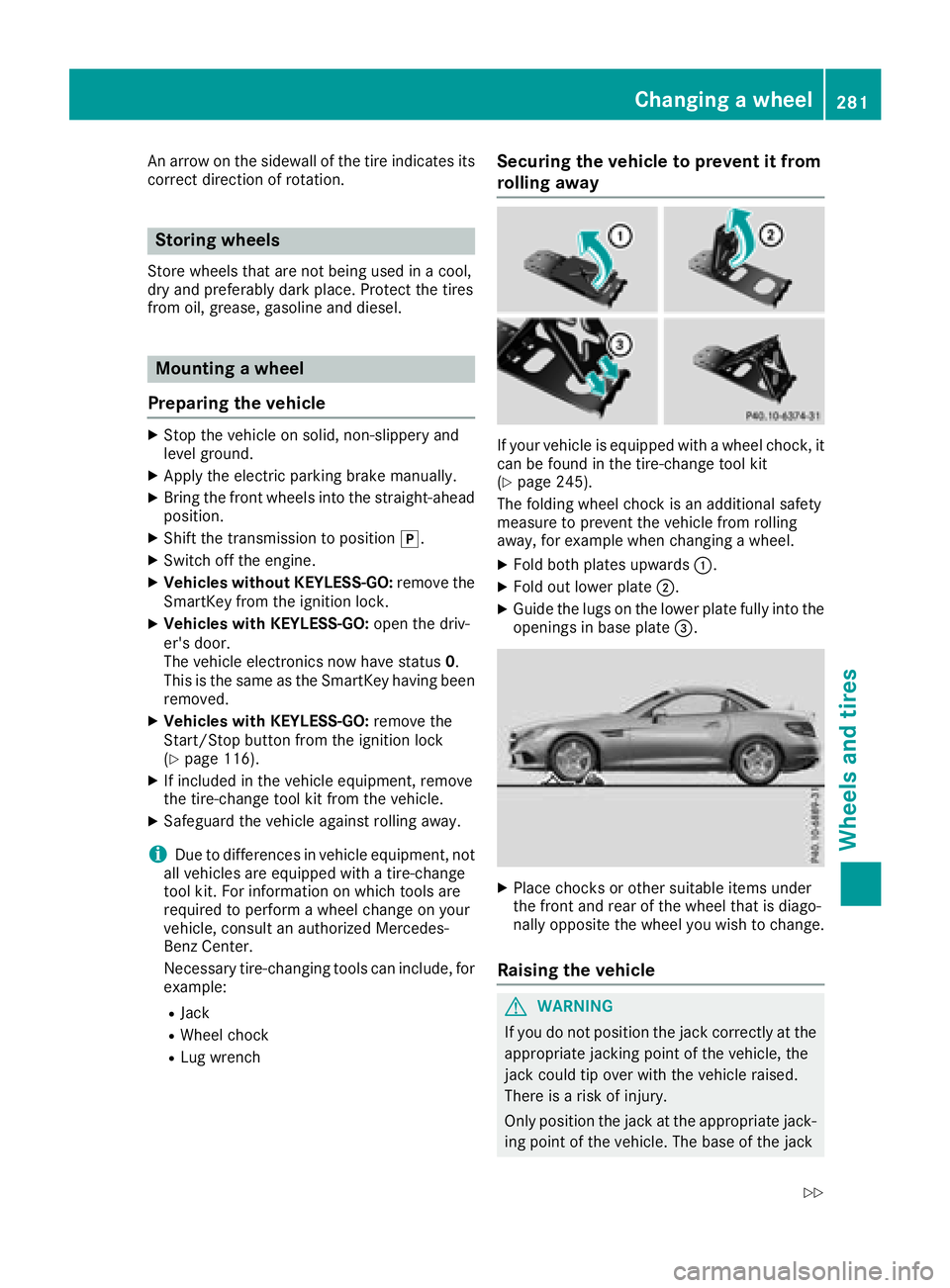
If your vehicl eisequippe dwithaw heelchock, it
can be found in the tire-change tool kit
(
Ypage 245).
The folding whee lchoc kisana dditional safety
measure to prevent the vehicl efrom rolling
away ,for exampl ewhenc hanging awheel .
XFoldb othp late su pwar ds:.
XFoldo utlowe rplate ;.
XGuid ethe lugs on the lowe rplate full yinto the
openings in base plate =.
XPlace chocks or others uitabl eitems under
the front and rea rofthe whee lthati sdiago -
nally opposite the whee lyou wish to change.
Raisin gthe vehicle
GWARNING
If yo udon ot positio nthe jack correctl yatthe
appropriate jacking point of the vehicle, the
jack could tip overw itht he vehicl eraised.
There is ariskofi njury.
Onlyp ositiont he jack at the appropriate jack-
ing point of the vehicle. The base of the jack
Changin gawheel281
Wheel sand tires
Z
Page 284 of 298
must be positioned vertically, directly under
the jacking point of the vehicle.
!Only position the jack at the appropriate
jacking point of the vehicle. Otherwise, you
could damage the vehicle.
Observe the following when raising the vehicle:
RTo rais ethe vehicle, only use the vehicle-spe-
cific jack that has been tested and approved
by Mercedes-Benz. If used incorrectly, the
jack could tip over with the vehicler aised.
RThe jack is designed only to raiseand hold the
vehiclef oras hort time while awheelisb eing
changed. It must not be used for performing
maintenance work under the vehicle.
RAvoid changing the wheelonu phill and down-
hill slopes.
RBefore raising the vehicle, secure it from roll-
ing awa ybyapplying the parking brake and
inserting wheelc hocks. Do not disengage the
parking brake whilet he vehicleisraised.
RThe jack must be placed on afirm, flat and
non-slip surface. On aloose surface, alarge,
flat, load-bearing underlay must be used .Ona
slippery surface, anon-slip underlay must be
used ,e.g. rubber mats.
RDo not use wooden blocks or similar objects
as ajack underlay.O therwise, the jack willn ot
be abletoa chieve its load-bearing capacity
due to the restricted height.
RMake sure that the distance betweent he
underside of the tires and the ground does not
exceed 1.2 in (3 cm).
RNever place you rhands and feet under the
raised vehicle.
RDo not lie under the vehicle.
RDo not start the engine when the vehiclei s
raised.
RDo not open or close adoor or the trunk lid
when the vehicleisr aised.
RMake sure that no persons are present in the
vehiclewhen the vehicleisr aised.
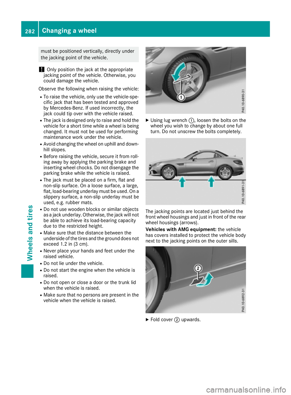
XUsing lug wrench:,loosent he bolts on the
wheely ou wish to change by abouto ne full
turn. Do not unscrew the bolts completely.
The jacking points are located just behind the
front wheelh ousings and just in front of the rear
wheelh ousings (arrows).
Vehicles with AMG equipment: the vehicle
has covers installed to protect the vehicleb ody
next to the jacking points on the outer sills.
XFold cover ;upwards.
282Changing awheel
Wheelsa nd tires
Page 285 of 298
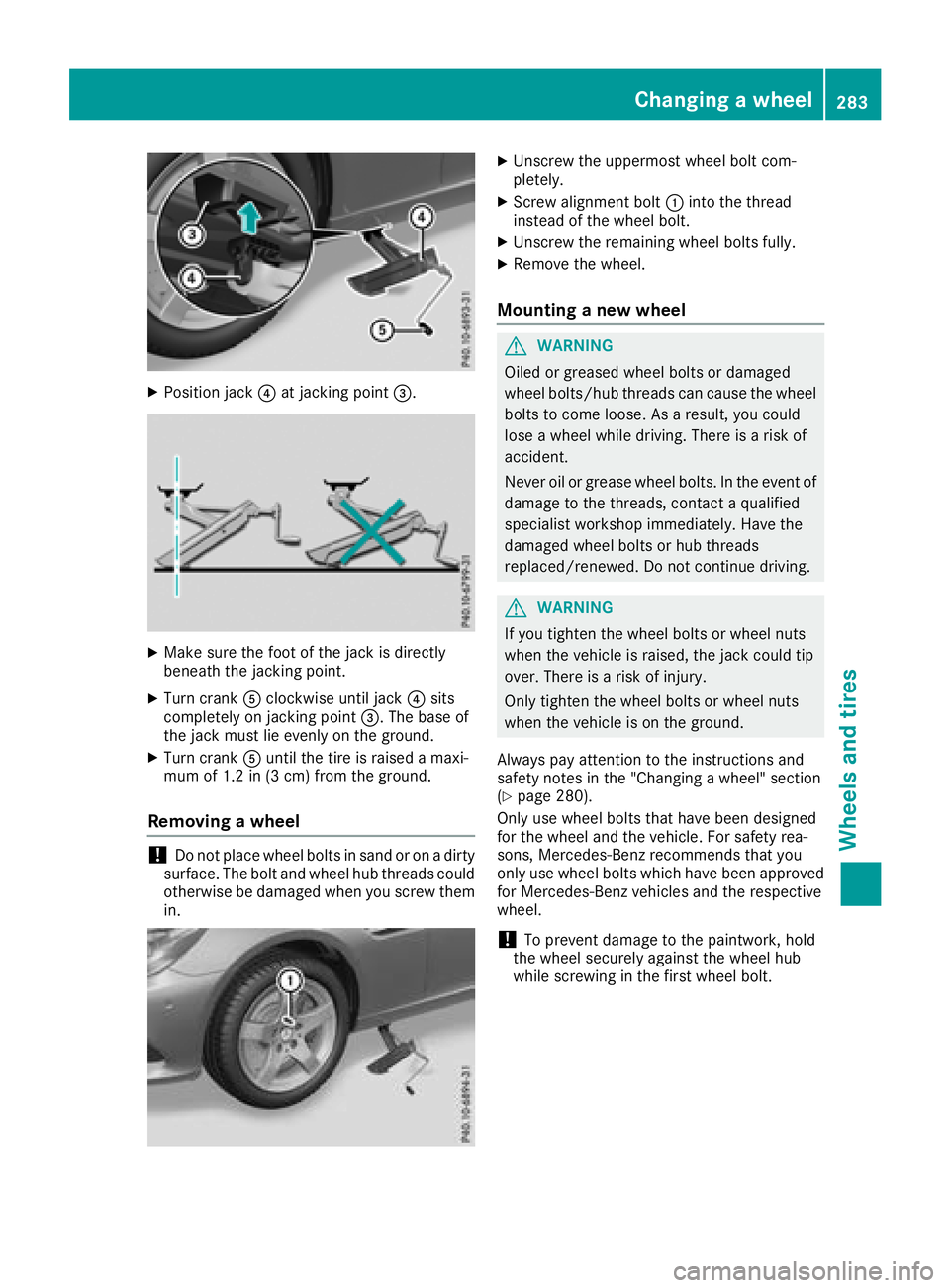
XPosition jack?at jacking point =.
XMake sure the foot of the jack is directly
beneath the jacking point.
XTurn crankAclockwise until jack ?sits
completely on jacking point =.The base of
the jack must lie evenly on the ground.
XTurn crank Auntil the tire is raised amaxi-
mum of 1.2 in (3 cm) from the ground.
Removing awheel
!Do not place wheel bolts in sand or on adirty
surface. The bolt and wheel hub threads could
otherwise be damaged when you screw them
in.
XUnscrew the uppermost wheel bolt com-
pletely.
XScrew alignment bolt :into the thread
instead of the wheel bolt.
XUnscrew the remaining wheel bolts fully.
XRemove the wheel.
Mounting anew wheel
GWARNING
Oiled or greased wheel bolts or damaged
wheel bolts/hub threads can cause the wheel bolts to come loose. As aresult, you could
lose awheel while driving. There is arisk of
accident.
Never oil or grease wheel bolts. In the event of
damage to the threads, contact aqualified
specialist workshop immediately. Have the
damaged wheel bolts or hub threads
replaced/renewed. Do not continue driving.
GWARNING
If you tighten the wheel bolts or wheel nuts
when the vehicle is raised, the jack could tip
over. There is arisk of injury.
Only tighten the wheel bolts or wheel nuts
when the vehicle is on the ground.
Always pay attention to the instruction sand
safety notes in the "Changing awheel" section
(
Ypage 280).
Only use wheel bolts that have been designed
for the wheel and the vehicle. For safety rea-
sons, Mercedes-Benz recommends that you
only use wheel bolts which have been approved for Mercedes-Benz vehicles and the respective
wheel.
!To prevent damage to the paintwork ,hold
the wheel securely against the wheel hub
while screwing in the first wheel bolt.
Changing awheel283
Wheels and tires
Z